Siemens SITRANS LC300 Operating Instructions Manual
Capacitance continuous level transmitter
Hide thumbs
Also See for SITRANS LC300:
- Instruction manual (38 pages) ,
- Quick start manual (115 pages)
Table of Contents
SITRANS LC300
SITRANS L
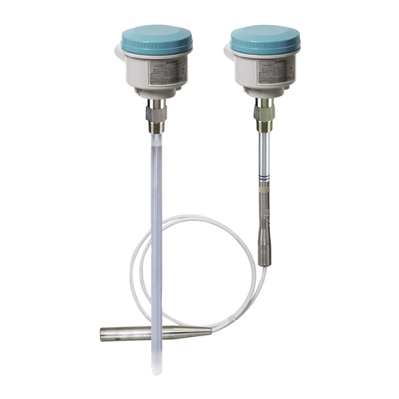
Capacitance continuous level
transmitter
SITRANS LC300
Operating Instructions
7ML5670 (LC300 standard, rod version)
7ML5671 (LC300 standard, stilling well version)
7ML5672 (LC300 standard, stainless steel cable
version)
7ML5673 (LC300 standard, PFA cable version)
05/2021
A5E47904073-AA
Safety notes
The Manual
SITRANS LC300
Installation
Wiring
Operation
Technical data
Dimensions
Technical references
Product documentation and
support
1
2
3
4
5
6
7
8
A
B
Table of Contents

Related Manuals for Siemens SITRANS LC300


Summary of Contents for Siemens SITRANS LC300
- Page 1 SITRANS LC300 Safety notes The Manual SITRANS L SITRANS LC300 Installation Capacitance continuous level transmitter Wiring SITRANS LC300 Operation Operating Instructions Technical data Dimensions Technical references Product documentation and support 7ML5670 (LC300 standard, rod version) 7ML5671 (LC300 standard, stilling well version)
- Page 2 Note the following: WARNING Siemens products may only be used for the applications described in the catalog and in the relevant technical documentation. If products and components from other manufacturers are used, these must be recommended or approved by Siemens. Proper transport, storage, installation, assembly, commissioning, operation and maintenance are required to ensure that the products operate safely and without any problems.
-
Page 3: Table Of Contents
Multiple units and wall restriction ..................13 Process cautions ........................ 14 Wiring ..............................17 Signal amplifier/power supply .................... 17 Connecting the SITRANS LC300 ..................18 Wiring setups for hazardous area installations ..............19 5.3.1 Flameproof / explosion proof configuration in hazardous areas ........... 19 Instructions specific to hazardous area ................ - Page 4 8.10 Shortening the cable ......................48 Technical references ..........................50 Technical References ......................50 SITRANS LC300 Pressure versus temperature curves ............51 A.2.1 LC300 Standard, extended rod, and cable versions, threaded ..........51 A.2.2 LC300 Standard, extended rod, and cable versions, ASME flanged ........52 A.2.3...
-
Page 5: Safety Notes
Safety notes Safety marking symbols In manual On Product Description Caution: refer to accompanying documents (manual) for de- tails. Earth (ground) Terminal Protective Earth Terminal SITRANS LC300 Operating Instructions, 05/2021, A5E47904073-AA... -
Page 6: The Manual
Note Follow the installation and operating procedures for a quick, trouble-free installation and to ensure the maximum accuracy and reliability of your SITRANS LC300. This manual applies to the SITRANS LC300 model only. This manual will help you set up your SITRANS LC300 for optimum performance. -
Page 7: Sitrans Lc300
SITRANS LC300 Note • SITRANS LC300 is to be used only in the manner outlined in this instruction manual, otherwise protection provided by the equipment may be impaired. • This product is intended for use in industrial areas. Operation of this equipment in a residential area may cause interference to several frequency based communications. -
Page 8: Features
SITRANS LC300 Features • Threaded and flanged process connections: see "Process connections" under "Electrodes" in Technical data (Page 31) • Corrosion resistant construction, PFA, PEEK , and 316L stainless steel wetted parts TM 1) • 5 m (16.4 ft) maximum insertion length for rod versions and 25 m (82 ft) maximum insertion length for cable versions •... -
Page 9: Installation
Note • Refer to the device nameplate for approval information. • SITRANS LC300 units are pressure tested, meeting or exceeding the requirements of the ASME Boiler and Pressure Vessel Code and the European Pressure Equipment Directive. • The serial numbers stamped in each process connection body provides a unique identification number indicating date of manufacture. -
Page 10: Pressure Equipment Directive, Ped, 97/23/Ec
Pressure Equipment Directive as pressure nor safety accessories (see EU Commission Guideline 1/8 and 1/20). SITRANS LC300 as supplied in the standard probe lengths is normally mounted on the vessel top or through the tank wall at the detection level (if used as Point Level switch). -
Page 11: Mounting
• Installation shall be performed only by qualified personnel and in accordance with local governing regulations. • This device is to be used only in the manner outlined in this manual. Otherwise, protection provided by the device may be impaired. SITRANS LC300 Operating Instructions, 05/2021, A5E47904073-AA... - Page 12 1900/4188 lbs. A rope probe with a PFA jacket reduces the amount of possible product buildup on the probe as well as the tensile force on the rope. SITRANS LC300 Operating Instructions, 05/2021, A5E47904073-AA...
-
Page 13: Multiple Units And Wall Restriction
Installation 4.7 Mounting 4.7.2 Multiple units and wall restriction Horizontally mounted units are configured as point level switches. Mount diagonally if vertical space is restricted. Note These drawings are not to scale. SITRANS LC300 Operating Instructions, 05/2021, A5E47904073-AA... -
Page 14: Process Cautions
Installation Process cautions CAUTION Keep unit out of path of falling material. CAUTION Consider material surface configuration when installing unit. SITRANS LC300 Operating Instructions, 05/2021, A5E47904073-AA... - Page 15 Installation 4.9 Process cautions CAUTION Tensile load must not exceed probe or vessel rating. SITRANS LC300 Operating Instructions, 05/2021, A5E47904073-AA...
- Page 16 Installation 4.9 Process cautions Note Buildup of material or condensation in active shield area does not affect operation. SITRANS LC300 Operating Instructions, 05/2021, A5E47904073-AA...
-
Page 17: Wiring
-40°C to 10 K above max. ambient temperature. Signal amplifier/power supply SITRANS LC300 uses a switched power supply circuit that makes the most efficient use of the available power present on the terminals. If the signal current is low (4 mA), the terminal voltage will increase due to a voltage drop of other components in the loop, and if the signal current is high (20 mA), the terminal voltage will decrease. -
Page 18: Connecting The Sitrans Lc300
Down / - button ⑥ Up / + button Connecting the SITRANS LC300 1. Loosen the retaining lid clip and remove the enclosure cover. 2. Loosen the cable gland and thread the cable through it. 3. Connect the power/signal conductor wires to the current-loop terminal blocks (any polarity). -
Page 19: Wiring Setups For Hazardous Area Installations
Technical data (Page 31) for the specific configuration you are about to use or install. • In potentially explosive atmospheres: – open the enclosure only when SITRANS LC300 is not energized. Note The transmitter is in operation when the power supply is switched on. -
Page 20: Instructions Specific To Hazardous Area
Notes for use in hazardous locations Use of this manual For use and assembly, refer to the instructions in this manual. It contains all instructions required by ATEX Directive 2014/34/EU, Annex II, 1/0/6 and Ordinance INMETRO n°179/2010. SITRANS LC300 Operating Instructions, 05/2021, A5E47904073-AA... - Page 21 II 1/2 D Ex ia/tb [ia Da] IIIC TX Da/Db Flameproof / Dust ignition proof with intrinsically safe output to probe II 1/2 G Ex ia/db [ia Ga] IIC TX Ga/Gb II 1/2 D Ex ia/tb [ia Da] IIIC TX Da/Db SITRANS LC300 Operating Instructions, 05/2021, A5E47904073-AA...
-
Page 22: Specific Condition Of Use
Aggressive substances: e.g., acidic liquids or gases that may attack metals, or solvents that may affect polymeric materials. Suitable precautions: e.g., establishing from the material's data sheet that it is resistant to specific chemicals. Cable entry devices / blanking elements general Dust ignition proof: SITRANS LC300 Operating Instructions, 05/2021, A5E47904073-AA... - Page 23 Tightening torque: Number of turns depending on the overall cable diameter of the used cable (e.g., 1 turn / cable diameter 12.5 mm to 5.5 turns / cable diameter 6.5 mm) Blanking element M20 X 1.5 (all versions) Tightening torque: 32.5 Nm SITRANS LC300 Operating Instructions, 05/2021, A5E47904073-AA...
-
Page 24: Operation
Limits required with 3.6 mA fault protection setting If the SITRANS LC300 is to be programmed for "fault protection setting to 3.6 mA" which is obtained by using the rotary switch position 3 and pushing the down button. Then, the following ambient temperature and input voltage limits must be observed: •... -
Page 25: Menu Functions
• In case of a system fault, the display alternates between PV value and Flt. View the fault details in menu 4. • Pressing either or both push-buttons in menu 0 has no effect. SITRANS LC300 Operating Instructions, 05/2021, A5E47904073-AA... -
Page 26: Menu Position 1
10, 100, and 1000 (displayed as 1E3). When no button is pressed for 4 sec- onds, the step size decreases to the next smallest value. At each step size, press the buttons for less than 1 second to adjust the value. SITRANS LC300 Operating Instructions, 05/2021, A5E47904073-AA... -
Page 27: Menu Position 3
Holding the Down button for longer than 1 second will change the fault protection setting to C:Lo. Both buttons • Pressing both buttons for more than 1 second disables the system fault protection and the LCD will read C:An. SITRANS LC300 Operating Instructions, 05/2021, A5E47904073-AA... -
Page 28: Menu Position 4
For example: If fault value 1 and fault value 2 occur together, the display will read fault value 3. If the display reads fault value 10, it means fault value 8 and fault value 2 have occurred together. SITRANS LC300 Operating Instructions, 05/2021, A5E47904073-AA... -
Page 29: Menu Position 5
If probe is rarely or never fully covered, set the LC300 to your application based on the following ex- ample: LRV (0%) Menu 1 reads 12.5 pF Actual level is at 45% of the measurement length of probe: PV (45%) Menu 0 reads 37 pF SITRANS LC300 Operating Instructions, 05/2021, A5E47904073-AA... -
Page 30: Maintenance
Please note the following: • The user is responsible for all changes and repairs made to the device. • All new components must be provided by Siemens Milltronics Process Instruments Inc. • Restrict repair to faulty components only. -
Page 31: Technical Data
Technical data Note Siemens makes every attempt to ensure the accuracy of these specifications, but reserves the right to change them at any time. Note EMC testing EN 61326 (CE EMC) testing was conducted on the product while mounted in a metallic vessel and wired using shielded cable, where the cable shield was terminated in an EMC cable gland at the device entry point. - Page 32 Upper Range Value (URV) 100% of scale value and adjustment menu position 3 Actual mA signal and system fault setting according to NAMUR NE 43 menu position 4 Diagnostic information/Software revision/reset menu position 5 Damping SITRANS LC300 Operating Instructions, 05/2021, A5E47904073-AA...
- Page 33 Zone 1 (ATEX II 1/2G) - Stainless steel, 1.4404 (316L) - Glass, Inconel 600 (Glass seal) Note The use of approved watertight conduit hubs/glands is required for Type 4/IP65 or IP68 (outdoor applications). SITRANS LC300 Operating Instructions, 05/2021, A5E47904073-AA...
- Page 34 Technical data Weight • Depends on configuration. Process Note • See SITRANS LC300 Pressure versus temperature curves (Page 51). • Not recommended for direct steam contact Pressure range -1 to 35 bar g (-14.6 to 511 psi g) Temperature range Without temperature extended shaft: -40 to 85°C (-40 to 185°F)
-
Page 35: Dimensions
⑦ Electronics (power supply and signal processing) ⑧ Driver ⑨ Safety barrier (not applicable for General Purpose) ⑩ Aluminum enclosure (Type 4/ NEMA 4/IP 65, IP68 optional) ⑪ Rod with PFA insulation SITRANS LC300 Operating Instructions, 05/2021, A5E47904073-AA... -
Page 36: Threaded Rod Version With Pfa Probe
Dimensions Threaded Flanged 125 mm (4.9") 105 mm (4.1") 170 mm (6.7") 150 mm (5.9") 120 mm (4.7") 100 mm (3.9") Threaded rod version with PFA probe SITRANS LC300 Operating Instructions, 05/2021, A5E47904073-AA... -
Page 37: Threaded Rod Version With Pfa Probe And Stilling Well
⑥ Y01 (insertion length) min = 300 mm (11.8") max = 5000 mm (197") ③ Lid clip ⑦ Measuring length ④ ⑧ 30 mm (1.18") inactive tip Threaded rod version with PFA probe and stilling well SITRANS LC300 Operating Instructions, 05/2021, A5E47904073-AA... - Page 38 ⑤ Y01 (insertion length) min = 300 mm (11.8") max = 5000 mm (197") ② Vent ⑥ Measuring length ③ Stainless steel stilling well ⑦ 30 mm (1.18") inactive tip ④ Y02: 120 mm (4.7”) SITRANS LC300 Operating Instructions, 05/2021, A5E47904073-AA...
-
Page 39: Cable Version, Non-Insulated, Threaded
① Stainless steel weight ④ Y01 (insertion length) min. = 1000 mm (40") max. = 25000 mm (984") ② Stainless steel cable ⑤ Measuring length ③ Y02 = 125 mm (4.9") SITRANS LC300 Operating Instructions, 05/2021, A5E47904073-AA... -
Page 40: Cable Version, Insulated, Threaded
Dimensions Cable version, insulated, threaded Note For liquids and solids applications. Insulated cable cannot be shortened. Weight is not included in measuring length. SITRANS LC300 Operating Instructions, 05/2021, A5E47904073-AA... - Page 41 ④ Y01 (insertion length) min. = 1000 mm (40") max. = 25000 mm (984") Note For conductive materials, the measuring length includes the exposed PFA insulated cable only. Any fluid contact with the upper rod assembly will result in a short circuit and incorrect readings. SITRANS LC300 Operating Instructions, 05/2021, A5E47904073-AA...
-
Page 42: Welded Flange
Electronics enclosure ③ Lid clip ④ ⑤ Y02 = 100 mm (3.9') ⑥ Y01 (insertion length) min. = 300 mm (11.81") max. = 5000 mm ⑦ Measuring length ⑧ 30 mm (1.18") inactive tip SITRANS LC300 Operating Instructions, 05/2021, A5E47904073-AA... - Page 43 Dimensions 8.10 Welded flange Flange Facing Flange class Flange thickness Δ ASME 150/300 2 mm (0.08") Δ ASME 600/900 7 mm (0.28") Δ PN 16/40 2 mm (0.08") SITRANS LC300 Operating Instructions, 05/2021, A5E47904073-AA...
-
Page 44: Welded Flange, Threaded, With Stilling Well
⑤ Y01 (insertion length) min. = 300 mm (11.81") max. = 5000 mm ② Vent ⑥ Measuring length ③ Stainless steel stilling well ⑦ 30 mm (1.18") inactive tip ④ Y02 = 100 mm (3.9') SITRANS LC300 Operating Instructions, 05/2021, A5E47904073-AA... -
Page 45: Cable Version, Non-Insulated, Welded Flange
Dimensions 8.13 8.14 Cable version, non-insulated, welded flange Note For non-conductive applications only. Non-insulated cable can be shortened on site. Weight is included in measuring length. SITRANS LC300 Operating Instructions, 05/2021, A5E47904073-AA... - Page 46 8.14 Cable version, non-insulated, welded flange ① Stainless steel weight ④ Y01 (insertion length) min. = 1000 mm (39.37") max. = 25000 mm (984.25") ② Stainless steel cable ⑤ Measuring length ③ Y02 = 105 mm (4.1') SITRANS LC300 Operating Instructions, 05/2021, A5E47904073-AA...
-
Page 47: Cable Version, Insulated, Welded Flange
⑤ Measuring length PFA insulated) ② PFA insulated cable ⑥ See note ③ Y02 = 105 mm (4.1') ⑦ Mounting eye ④ Y01 (insertion length) min. = 1000 mm (39.37") max. = 25000 mm (984.25") SITRANS LC300 Operating Instructions, 05/2021, A5E47904073-AA... -
Page 48: Cable Tensile Strength
3. Ensure that cable strands are properly seated in the lay of the cable (i.e. no wire strands sticking outside the normal cable profile). Make sure all strands are properly seated before continuing the assembly. SITRANS LC300 Operating Instructions, 05/2021, A5E47904073-AA... - Page 49 Make sure that no cable strands are pushed out of their position in the cable and that the cable is fully inserted. 5. Re-fasten the weight by tightening the three set screws. SITRANS LC300 Operating Instructions, 05/2021, A5E47904073-AA...
-
Page 50: Technical References
Note • Refer to the device nameplate for approval information. • SITRANS LC300 units are pressure tested, meeting or exceeding the requirements of the ASME Boiler and Pressure Vessel Code and the European Pressure Equipment Directive. • The serial numbers stamped in each process connection body provides a unique identification number indicating date of manufacture. -
Page 51: Sitrans Lc300 Pressure Versus Temperature Curves
Technical references SITRANS LC300 Pressure versus temperature curves A.3.1 LC300 Standard, extended rod, and cable versions, threaded WARNING • For pressure applications, use PTFE tape or other appropriate thread sealing compound and tighten the process connection beyond hand-tight. • The use of PTFE tape or other appropriate sealant may be used to aid in sealing the threads for use in pressure applications. -
Page 52: Lc300 Standard, Extended Rod, And Cable Versions, Asme Flanged
Technical references A.3 SITRANS LC300 Pressure versus temperature curves A.3.2 LC300 Standard, extended rod, and cable versions, ASME flanged WARNING • The user is responsible for the selection of bolting and gasket materials which will fall within the limits of the flange and its intended use, and which are suitable for the service conditions. -
Page 53: Lc300 Standard, Extended Rod, And Cable Versions, En Flanged
Technical references A.3 SITRANS LC300 Pressure versus temperature curves A.3.3 LC300 Standard, extended rod, and cable versions, EN flanged ① Atmospheric ② P = Permitted Operating Pressure ③ PN 40 ④ PN 16 ⑤ T = Permitted Operating Temperature The curve denotes the minimum allowable flange class for the shaded area below. -
Page 54: Product Documentation And Support
Entering a serial number 1. Open the PIA Life Cycle Portal (https://www.pia-portal.automation.siemens.com). 2. Select the desired language. 3. Enter the serial number of your device. The product documentation relevant for your device is displayed and can be downloaded. -
Page 55: Technical Support
In addition to our technical support, Siemens offers comprehensive online services at Service & Support (http://www.siemens.com/automation/serviceandsupport). Contact If you have further questions about the device, contact your local Siemens representative at Personal Contact (http://www.automation.siemens.com/partner). To find the contact for your product, go to "all products and branches" and select "Products &... - Page 56 Product documentation and support B.3 Technical support Short form Long Form Description Units Stilling Well Grounded metal tube with openings Upper Range Value value for 100% (in pF) 20 mA SITRANS LC300 Operating Instructions, 05/2021, A5E47904073-AA...
-
Page 57: Index
39, 40, 43, 44, 45, 47 standard, 36, 37 display, 32 operation, 24 Downloads, 54 position 0, 25 fault values, 28 position 1, 26 features, 8 position 2, 26 position 3, 27 position 4, 28 SITRANS LC300 Operating Instructions, 05/2021, A5E47904073-AA... - Page 58 SITRANS LC 300 applications, 7 configuration, 35 features, 8 start up, 24 Support, 55 Support request, 55 system fault protection, 27 Technical support, 55 partner, 55 personal contact, 55 upper range value, 26 URV, 26 SITRANS LC300 Operating Instructions, 05/2021, A5E47904073-AA...