Table of Contents
Available languages
Available languages
Quick Links
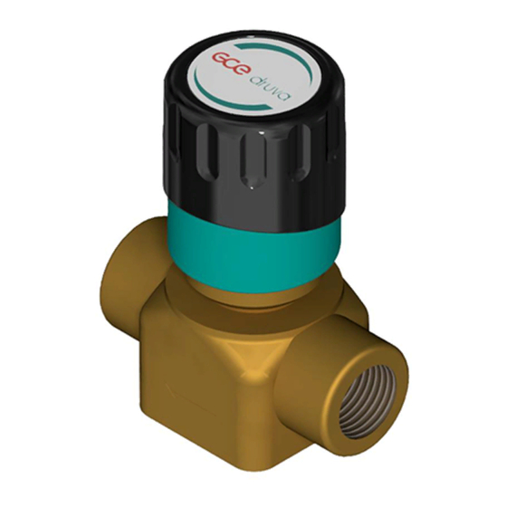
2-PORT SHUT-OFF VALVE
2-PORT ABSPERRVENTIL
V – VALVE | P-PUR | M – MIDDLE FLOW
INSTRUCTION FOR USE
GEBRAUCHSANLEITUNG
IMPORTANT!
Read carefully before use! Keep the manual for future consultation!
WICHTIG!
Vor Gebrauch sorgfältig lesen!
Bewahren Sie die Gebrauchsanweisung für späteres Nachschlagen auf!
GCE CENTRAL GAS SYSTEMS
EN
DE
Chapters
Table of Contents

Related Manuals for GCE Druva VPMA


Summary of Contents for GCE Druva VPMA
- Page 1 GCE CENTRAL GAS SYSTEMS 2-PORT SHUT-OFF VALVE 2-PORT ABSPERRVENTIL V – VALVE | P-PUR | M – MIDDLE FLOW INSTRUCTION FOR USE GEBRAUCHSANLEITUNG IMPORTANT! Read carefully before use! Keep the manual for future consultation! WICHTIG! Vor Gebrauch sorgfältig lesen! Bewahren Sie die Gebrauchsanweisung für späteres Nachschlagen auf!
-
Page 2: Table Of Contents
CONTENT 1 General ......................................4 1.1 information about this instructions manual ........................4 1.2 Information about this shut-off valve ..........................4 1.3 explanation of symbols ................................. 4 1.4 Limitations of liability ................................5 1.5 Copyright ....................................5 1.6 Spare parts ....................................5 1.7 Warranty provision ................................. - Page 3 6 Installation and initial start-up ...........................14 6.1 Safety notes for installation and initial start-up ......................14 6.2 Preparation ....................................14 6.3 Installation ....................................14 6.4 Required qualifications for initial start-up and cylinder changing ................14 6.5 Initial Start Up..................................14 6.5.1 Fill the process gas tubing with process gas .......................14 6.5.2 Taking gas supply out of operation ........................14 6.6 Tests ......................................14 7 Operation...
-
Page 4: General
ENGLISH INSTRUCTION FOR USE: 2-PORT SHUT-OFF VALVE 1. GENERAL 1.1. INFORMATION ABOUT THIS INSTRUCTIONS MANUAL This instruction is only intended for use with shut off valve type: VPMA – 2-Port Shut Off Valve, 1x Inlet, 1x Outlet This type of valve is suitable to interrupt the gas flow. They were assembled into piping permanently. These instructions enable you to operate the system safely and efficiently. -
Page 5: Limitations Of Liability
NOTE! This combination of symbol and signal word indicates a pos- sibly dangerous situation that can cause property and environ- mental damage if not avoided. TIPS AND RECOMMENDATIONS This symbol highlights useful tips and recommendations, to- gether with help for ensuring efficient and trouble-free opera- tion. -
Page 6: Warranty Provision
1.7. WARRANTY PROVISION The warranty provisions are included in the manufacturer’s general terms and conditions of business. See chapter VI. Warranty Claims. 1.8. CUSTOMER SERVICE GCE GmbH Weyherser Weg 8 DE-36043 Fulda +49 (0) 661 8393 -0 www.gcegroup.com [email protected] Please do not hesitate to provide us with information and experiences gained through use; we welcome any valuable input that will help to improve our products. -
Page 7: Operator's Responsibility
THEREFORE: • Sufficient ventilation is absolutely essential. • Installation only through certified company. • Observe ATEX directive ATTENTION! • Risk of injury from environment! There can be malfunctions on component due to condensation and/ or icing. THEREFORE: • Observe suitable temperatures. •... -
Page 8: Personnel Requirements
OPERATOR’S DUTIES The system is used for commercial purposes. The operator of the system is therefore subject to legal work safety obligations. Compliance with the safety, accident prevention and environmental protection regulations that apply for the use of the system is mandatory, in addition to the safety information in these instructions. THE FOLLOWING APPLIES IN PARTICULAR: •... -
Page 9: Training
2.4.3. TRAINING The operator must train the staff at regular intervals. A training log must be maintained for purposes of better tracking and must contain the following information, at least: • Date of training • Names of trained staff • Contents of the training session •... -
Page 10: Environmental Protection
MEASURES IN THE EVENT OF FIRE OR ACCIDENT • If there is no risk to your own safety, remove people from the danger zone. • Administer first aid if necessary. • Notify the fire brigade and/or emergency service. • In the event of fire: If there is no risk to your own safety, use fire extinguishing equipment to fight the fire until the fire brigade arrives. -
Page 11: Technical Specifications
3. TECHNICAL SPECIFICATIONS 3.1. DIMENSION – VPMA 3.2. GENERAL INFORMATION Information Value Unit Weight (max.) 0,32 Diameter Height 90,4 3.3. CONNECTION VALUES Information Value Unit Inlet ½“ 10, 12, 15, 18 fitting mm ¼“, 3/8“, ½“ fitting inch Outlet ½“ 10, 12, 15, 18 fitting mm 3/8“, ½“, ¾“... -
Page 12: Flow Chart
3.5. FLOW CHART 3.6. OPERATING CONDITIONS Information Value Unit Temperature range -20 till +60 °C Relative humidity (max.) 4. SET-UP AND FUNCTION 4.1. OVERVIEW – VPMA Handwheel to close the valve Valve Inlet - different connections possible Valve Outlet - different connections possible 4.2. -
Page 13: Transport, Packaging And Storage
5. TRANSPORT, PACKAGING AND STORAGE TIPS AND RECOMMENDATIONS! • The installation and start- up of this gas supply panel is normally done by the supplier or by authorized personnel. • Even though there can be some users or maintenance personnel who care about the packaging. The fol- lowing notes should be observed accordingly. -
Page 14: Installation And Initial Start-Up
TIPS AND RECOMMENDATIONS! • Some packages may bear labels with storage information that extends beyond these requirements. These notes should be observed accordingly. 6. INSTALLATION AND INITIAL START-UP 6.1. SAFETY NOTES FOR INSTALLATION AND INITIAL START-UP STAFF Installation and initial start-up of the system may only be performed by qualified staff. 6.2. -
Page 15: Operation
7. OPERATION In reference to chapter 2.1 the operation of the shut-off valve is defined. BEWARE! • Valves must always be opened slowly and carefully to prevent pressure surges in the system and damage to the other components! 8. MAINTENANCE 8.1. -
Page 16: Measures Following Maintenance
• Check function • Pressure test with 1-times working pressure for 12 hours • Worn and defective components must be changed immediately from authorized qualified company • Valve is designed according to ISO 10297, including type test with cycle test from up to 2000 cycles. Change inner parts after 2000 cycles, change must be done from authorized qualified company •... - Page 17 Description Reason Solution Valve Cylinder Line Regulator Regulator Supply Panel Slight increase Inlet pressure No failure, nor- of outlet pres- drop mal operating sure & relief state valve does not open Slight increase Difference No failure, nor- of outlet pres- between flow mal operating sure...
-
Page 18: Dismantling And Disposal
Description Reason Solution Valve Cylinder Line Regulator Regulator Supply Panel No changes of Defect Repair by valve control handwheel be- manufacturer when turning cause of too the handwheel high torque, defect of spindle, defect of thread Moisture on Pressure regu- No failure, nor- pressure regu- lator withdraw... -
Page 19: Disposal
Plastics: recycle. Other components: sort and dispose. In accordance to Article 33 of REACH GCE, s.r.o. as responsible manufacturer shall inform all customers if materials containing 0.1% or more of substances included in the list of Substance of Very High Concern (SVHC). - Page 20 INHALT 1 Allgemeines ....................................22 1.1 Information zu dieser Anleitung ............................22 1.2 Information zum Ventil ................................22 1.3 Symbolerklärung .................................22 1.4 Haftungsbeschränkung ..............................23 1.5 Urheberschutz ..................................23 1.6 Ersatzteile ....................................24 1.7 Gewährleistungsbestimmungen ............................24 1.8 Kundenservice ..................................24 2 Sicherheit ....................................24 2.1 Bestimmungsgemäße Verwendung ..........................24 2.1.1 Bauliche Veränderung am Absperrventil .......................24 2.2 Grundsätzliche Gefahren ..............................25 2.3 Verantwortung des Betreibers ............................26...
- Page 21 6 Installation und Erstinbetriebnahme ........................32 6.1 Sicherheitshinweise für die Installation und Erstinbetriebnahme ................32 6.2 Vorbereitungen ...................................32 6.3 Installation .....................................32 6.4 Voraussetzung zur Erstinbetriebnahme........................32 6.5 Erstinbetriebnahme ................................32 6.5.1 Füllen der Prozessgasleitung mit Prozessgas ....................32 6.5.2 Außerbetriebnahme der Anlage ........................... 33 6.6 Prüfungen ..................................... 33 7 Betrieb .......................................
-
Page 22: Allgemeines
DEUTSCH GEBRAUCHSANLEITUNG: 2-PORT ABSPERRVENTIL 1. ALLGEMEINES 1.1. INFORMATION ZU DIESER ANLEITUNG Diese Anleitung gilt für Absperrventile des Typs: • VPMA – 2-Port Absperrventil, 1x Eingang, 1x Ausgang Ventile dieses Typs dienen zur Unterbrechung des Gasflusses. Sie werden dauerhaft im Rohrleitungsnetz eingebaut. -
Page 23: Haftungsbeschränkung
VORSICHT! Diese Kombination aus Symbol und Signalwort weist auf eine möglicherweise gefährliche Situation hin, die zu geringfügigen oder leichten Verletzungen führen kann, wenn sie nicht gemi- eden wird. HINWEIS! Diese Kombination aus Symbol und Signalwort weist auf eine möglicherweise gefährliche Situation hin, die zu Sach- und Umweltschäden führen kann, wenn sie nicht gemieden wird. -
Page 24: Ersatzteile
Bei Verwendung nicht zugelassener Ersatzteile erlischt die Herstellergarantie 1.7. GEWÄHRLEISTUNGSBESTIMMUNGEN Die Gewährleistungsbestimmungen sind in den Allgemeinen Geschäftsbedingungen des Herstellers en- thalten. Siehe AGBs Abschnitt VI. Mängelansprüche. 1.8. KUNDENSERVICE GCE GmbH Weyherser Weg 8 DE-36043 Fulda +49 (0) 661 8393 -0 www.gcegroup.com [email protected]... -
Page 25: Grundsätzliche Gefahren
Geräuschentwicklung In einigen Fällen kann das ungünstige Zusammenwirken bestimmter Einflussgrößen, wie z.B. Durchfluss und Druckbereich, aber auch die Gasart selbst zu Geräuschentwicklung führen. Bitte setzen Sie sich in diesen Fällen mit dem Hersteller in Verbindung. 2.2. GRUNDSÄTZLICHE GEFAHREN Im folgenden Abschnitt sind Restrisiken benannt, die vom Gerät auch bei bestimmungsgemäßer Verwend- ung ausgehen können. -
Page 26: Verantwortung Des Betreibers
WARNUNG! • Unfallgefahr! • Durch falsche Installation kann es zu ernsthafte oder sogar tödliche Verletzungen kommen. DAHER: • Sicherung der Geräte vor Herunterfallen während der Installation! • Geräte nicht werfen! Drucktragende Teile sind nur für die bestimmungsgemäße Verwendung zu benutzen. Bei mechanischer Beschädigung der Rohrleitungen und Armaturen muss das System in den sicheren Zu- stand gebracht werden (betroffenen Abschnitt sperren). -
Page 27: Unterweisung
In dieser Anleitung werden die im Folgenden aufgeführten Qualifikationen der Personen für die ver- schiedenen Aufgaben benannt: GASTECHNIK-INGENIEUR Besitzt Fachausbildung, Fähigkeiten, Erfahrung und Wissen bezüglich relevanter Normen und Richtlinien um Arbeiten an Druckregelsystemen vornehmen zu können und potentielle Risiken zu erkennen. Gastech- nik-Ingenieure sind speziell geschult im Hinblick auf die jeweilige Produktionsstätte und deren spezifische Standards und Richtlinien. -
Page 28: Verhalten Bei Feuerausbruch Und Bei Unfällen
HANDSCHUHE, CHEMISCH RESISTENT Schutz der Hände vor aggressiven Substanzen. Es ist auf Dichtigkeit der Hands- chuhe acht zu geben. Nach Gebrauch Handschuhe fachgerecht entsorgen. SCHUTZHANDSCHUHE Schutz der Hände vor mechanischen Einflüssen und heißen Oberflächen. GEHÖRSCHUTZ TRAGEN Schützt das Gehört vor zu lauten Geräuschen und beugt Schalltraumata vor. 2.6. -
Page 29: Warnzeichen
2.8.3. WARNZEICHEN WARNUNG VOR GASFLASCHEN WRNUNG VOR WARNUNG VOR GIFTIGEN UND/ EXPLOSIONSFÄHIGER ODER KORROSIVEN STOFFEN ATMOSPHÄRE 3. TECHNISCHE DATEN 3.1. MASSBLATT – VPMA 3.2. ALLGEMEINE ANGABEN Angabe Wert Einheit Gewicht 0,32 Durchmesser Höhe 90,4 3.3. ANSCHLUSSWERTE Angabe Wert Einheit Eingang ½“... -
Page 30: Leistungswerte
3.4. LEISTUNGSWERTE Angabe Wert Einheit Druck (max.) 3.5. DURCHFLUSSKURVE 3.6. BETRIEBSBEDINGUNGEN UMGEBUNG Angabe Wert Einheit Temperaturbereich -20 bis +60 °C Relative Luftfeuchte (max.) 4. AUFBAU UND FUNKTION 4.1. AUFBAU - VPMA Handrad zum Absperren des Ventils Ventil Eingang-verschiedene Anschlüsse wählbar Ventil Ausgang-verschiedene Anschlüsse wählbar 30/40... -
Page 31: Kurzbeschreibung
4.2. KURZBESCHREIBUNG Die Bedienung des Absperrventils erfolgt manuell durch das Handrad. Durch Drehen des Handrades gegen den Uhrzeigersinn wird das Ventile geöffnet, durch drehen im Uhrzeigersinn geschlossen. 5. TRANSPORT, VERPACKUNG UND LAGERUNG TIPPS UND EMPFEHLUNGEN! • Die Installation und Erstinbetriebnahme erfolgt idealerweise durch Mitarbeiter des Herstellers oder durch von ihm autorisierte Personen. - Page 32 • Lagertemperatur: 15 bis 35 °C. • Relative Luftfeuchtigkeit: max. 60 %. • Bei Lagerung länger als 3 Monate regelmäßig den allgemeinen Zustand aller Teile und der Verpackung kontrollieren. Falls erforderlich, die Konservierung auffrischen oder erneuern. TIPPS UND EMPFEHLUNGEN! • Unter Umständen befinden sich auf den Packstücken Hinweise zur Lagerung, die über die hier genannten Anforderungen hinausgehen.
- Page 33 6.6. PRÜFUNGEN • Nach der Druckbeaufschlagung die Funktion des Absperrventils überprüfen 7. BETRIEB Gemäß Kapitel 2.1 ist der Betrieb Absperrventils für Standardgase definiert. VORSICHT! • Handventile müssen immer langsam und vorsichtig geöffnet werden, um Druckstöße im System zu ver- meiden und andere Komponenten zu schützen. 8.
- Page 34 8.3.3. NOTWENDIGE WARTUNGSLEISTUNG • Prüfung der Anzeigegenauigkeit des Anzeigewertes bei Druckanzeigen. • Entspannungsstation, Druckregler, Ventile und Druckanzeigen: Zustand auf Funktion, Zustand und Ken- nzeichnung prüfen. • Prüfung der Kennzeichnung. • Prüfung auf Korrosion. • Prüfung der Funktion. • Dichtheitsprüfung mit 1-fachem Betriebsdruck über 12 Stunden ausführen. •...
- Page 35 Beschreibung Ursache Lösung Ventile Flaschen- Leitungs- Entspannungs- druckregler druckregler stationen Kein Durch- Flaschen- Inbetrieb- fluss (beide ventil nahme gemäß Manometer geschlossen Punkt 6. In- zeigen Null) Brauch- stallation und gasventil Erstinbetrieb- geschlossen nahme Druckregler geschlossen Wendel/ Schlauch nicht ange- schlossen Kein Durch- Druckregler Druckregler...
- Page 36 Beschreibung Ursache Lösung Ventile Flaschen- Leitungs- Entspannungs- druckregler druckregler stationen Ausgangs- Falsche Druckregler druck zu hoch Regler Ein- Einstellung stellung anpassen, nachregeln, Wartung Hinterdruck Verschmut- Reparatur steigt sofort zung oder durch Herstel- bis Anschlag Beschä- an oder digung Hinterdruck des Sitzes steigt langsam „Steiger“...
- Page 37 Kunststoffelemente zum Recycling geben. Übrige Komponenten nach Materialbeschaffenheit sortiert entsorgen. Gemäß dem Artikel 33 der REACH-Verordnung verpflichtet sich die Gesellschaft GCE, s.r.o. als verantwor- tungsbewusster Hersteller, alle Kunden darüber zu informieren, wenn die Materialien 0,1% oder mehr der auf der Liste aufgeführten besonders besorgniserregenden Stoffe (SVHC) enthalten.
- Page 38 Im Zweifel Auskunft zur umweltgerechten Entsorgung bei der örtlichen Kommunalbehörde oder speziel- len Entsorgungsfachbetrieben einholen. HERSTELLER: GCE s.r.o. Tel : +420 569 661 111 Zizkova 381 Fax : +420 569 661 602 583 01 Chotebor http://www.gcegroup.com Czech Republic © GCE s.r.o. 38/40...
- Page 39 39/40...
- Page 40 Manufacturer: GCE s.r.o. Žižkova 381, 583 01 Chotěboř, Česká republika http://www.gcegroup.com Doc. Nr.: IFU-VPMA; DOI: 2020-01-16; Rev.:01; TI: A5, CB, V1...