
Related Manuals for Dell EMC PowerSwitch Z9432F-ON


Summary of Contents for Dell EMC PowerSwitch Z9432F-ON
- Page 1 Dell EMC PowerSwitch Z9432F-ON Installation Guide February 2021 February 2021 Rev. A00...
- Page 2 A WARNING indicates a potential for property damage, personal injury, or death. © 2021 Dell Inc. or its subsidiaries. All rights reserved. Dell, EMC, and other trademarks are trademarks of Dell Inc. or its subsidiaries. Other trademarks may be trademarks of their respective owners.
-
Page 3: Table Of Contents
Contents Chapter 1: About this guide......................5 Related documents................................5 Information symbols................................6 Chapter 2: The Z9432F-ON switch....................7 Introduction................................... 7 Features....................................8 Physical dimensions................................8 LED display.................................... 9 LED behavior...................................9 Prerequisites..................................10 Z9432F-ON switch configurations..........................11 Luggage tag..................................11 Chapter 3: Site preparations......................12 Site selection..................................12 Cabinet placement................................ - Page 4 USA Federal Communications Commission statement.................... 49 European Union EMC directive conformance statement..................49 Japan VCCI compliance for class A equipment......................50 Safety standards and compliance agency certifications..................50 Electromagnetic compatibility ............................51 Product recycling and disposal............................51 Chapter 11: Dell EMC support...................... 53 Contents...
-
Page 5: Chapter 1: About This Guide
For more information about the Z9432F-ON switch, see the following documents: ● Dell EMC SmartFabric OS10 User Guide ● Dell EMC SmartFabric OS10 Release Notes ● Dell EMC PowerSwitch Z9432F-ON Set-up Guide ● Dell EMC PowerSwitch Z9432F-ON Release Notes About this guide... -
Page 6: Information Symbols
● Dell EMC PowerSwitch Z9432F-ON BMC User Guide ● Open Networking Hardware Diagnostic Guide NOTE: To access product documentation for specific Dell EMC PowerSwitches, see the Dell EMC Networking OS10 Info Hub. For all other resources, see Dell EMC support: www.dell.com/support. -
Page 7: Chapter 2: The Z9432F-On Switch
The Z9432F-ON switch The following sections describe the Dell EMC Z9432F-ON switch. Topics: • Introduction • Features • Physical dimensions • LED display • Prerequisites • Z9432F-ON switch configurations • Luggage tag Introduction The Z9432F-ON switch is a 1U, full-featured fixed 10/25/40/50/100/200/400 GbE data center switch with 400 GbE optical interfaces for data center leaf aggregation. -
Page 8: Features
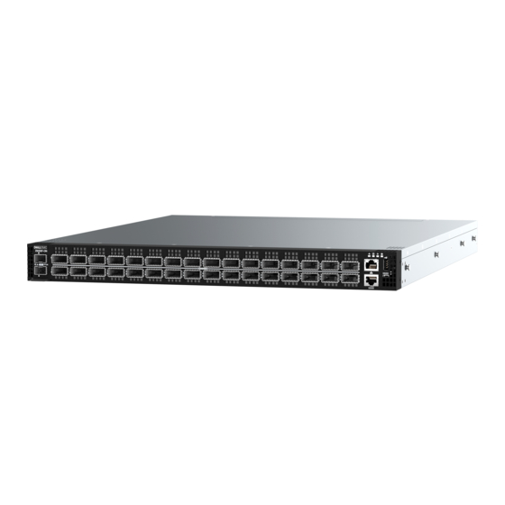
1. Two SFP+ ports 2. Thirty-two QSFP56-DD ports 3. RJ45 Ethernet port 4. LED status icons 5. USB Type A 6. Luggage tag 7. RJ45 console port 8. MicroUSB-B console port The Z9432F-ON switch PSU-side view: 1. AC PSUs 2. Fan modules Features The Z9432F-ON switch offers the following features: ●... -
Page 9: Led Display
○ Fan tray handle 25 mm (0.99 in) LED display The Z9432F-ON switch includes LED displays on the I/O side of the switch. This section describes open networking installation environment (ONIE) LED behaviors. Some LED behaviors may change after you install your software. LED behavior The following Z9432F-ON switch LED behavior is seen during ONIE operations: 1. -
Page 10: Prerequisites
Table 1. Z9432F-ON switch LED behavior (continued) Description LOCATOR LED/System Beacon ● Off—Locator function disabled ● Flashing blue—Locator function enabled Table 2. System management Ethernet port LED Description Link LED ● Off—No module present ● Solid green—Port link is up ●... -
Page 11: Z9432F-On Switch Configurations
400 GbE ports. Reverse airflow switches do not support high-power cables or optics. 400 GbE transceivers and active cables may exceed the Dell EMC PowerSwitch with High-Power Optics guide. supported threshold. For more information, see the... -
Page 12: Chapter 3: Site Preparations
Site preparations The Z9432F-ON switch is suitable for installation as part of a common bond network (CBN). You can install the switch in: ● Network telecommunication facilities ● Data centers ● Other locations where the National Electric Code (NEC) applies CAUTION: To avoid tangling cables or damaging optics, install the switch into a rack or cabinet before installing any additional components such as cables or optics. -
Page 13: Rack Mounting
Z9432F-ON switch installation. NOTE: For an AC-powered switch, although the third conductor of the AC power cable provides a ground path, Dell Technologies recommends grounding your switch with a dedicated ground wire. NOTE: For a DC-powered switch, the only way to safely ground your switch is to attach a dedicated ground wire. The ground lug ships inside the DC PSU shipping box. -
Page 14: Switch Power
Switch power To connect the switch to the applicable power source, use the appropriate power cable. An AC power cable is included with each PSU. When installing AC or DC switches, follow the code requirements appropriate for your country or region. For example, in the U.S., follow National Electrical Code ANSI/NFPA 70 and in Europe follow IEC60364. -
Page 15: Chapter 4: Z9432F-On Switch Installation
For an AC-powered switch, although the third conductor of the AC power cable provides a ground path, Dell Technologies recommends grounding your switch with a dedicated ground wire. Using a dedicated ground wire reduces equipment communication interference, offers ESD protection, and prevents possible equipment damage. -
Page 16: Rack Or Cabinet Hardware Installation Procedure
Rack or cabinet hardware installation procedure You may either place the switch on a rack shelf or mount the switch directly into a 19" wide, EIA-310 E-compliant rack. These installation procedures are for four-post rack installation only. The rails system includes separately packaged rail assemblies. Safety, Environmental, WARNING: This document is a condensed reference. - Page 17 3. Attach the inner rail to the switch. Line up the inner rail slot with the T-stud on the switch. Push the inner rail back until it clicks into place. 4. Confirm the rack mounting hole type and choose the correct components--EIA 9.5 mm (.354 in) square hole, EIA 7.1 mm (.279 in) round hole, or threaded hole.
- Page 18 For EIA 7.1 mm (.279 in) round hold racks, press the latch to change from square pegs to round pegs. For a threaded mounting hole, change the die-cast parts on the outer rail to the fitting plates shipped with the rails. Change the die-cast parts on both the front and rear side of the outer rail.
- Page 19 9.5 mm square hole rack EIA 7.1 mm (.279 in) round hole rack Z9432F-ON switch installation...
- Page 20 6. Attach the outer rail to the front of the four-post rack. The rail clicks into place. 7. Repeat these steps for the second rail. 8. Slide the inner rails that are attached to the switch into the outer rails that are attached to the rails. NOTE: Press the spring clip on each inner slide rail to allow the switch to slide into the outer rail.
- Page 21 9. Tighten the thumbscrews to secure the switch to the rack. To remove the switch, press the rail spring clip and pull the inner rail and switch out of the outer rail and rack. Z9432F-ON switch installation...
-
Page 22: Four-Post L-Bracket Rail Installation
To remove the outer rails from the rack, press the blue plastic button on each outer rail. Four-post L-bracket rail installation Use these installation instructions for racks with threaded holes, 9.5 mm (.354 in) square holes, or 7.1 mm (.279) round holes. Complete the switch installation in the following order: 1. - Page 23 NOTE: For the EIA 9.5 mm (.354 in) square-hole rack, insert the cage nuts into the rack holes before you secure the L-brackets to the rack. The cage nuts ship with the brackets and rails. To install the switch: 1. Remove the rails, L-brackets, and screws from the shipping container. 2.
- Page 24 Repeat this step to attach the second inner rail to the other side of the switch. 5. Attach the outer rail to the back of the four-post rack. Align the outer rail peg to the back of the four-post rack. Secure the outer rail to the back of the rack using two M4 screws for each rail.
- Page 25 7. Attach the L-brackets to the front of the four-post rack. Align the L-bracket holes to the holes at the front of the four-post rack. Secure the L-brackets to the front of the rack using two M4 screws for each side. Z9432F-ON switch installation...
-
Page 26: Optics Installation
Optics installation For a list of supported optics, see the specification sheets at www.dell.com/support or contact your Dell EMC Sales representative. WARNING: When working with optical fibers, follow all warning labels and always wear eye protection. Never look directly into the end of a terminated or unterminated fiber or connector as it may cause eye damage. -
Page 27: Optics Removal
Dell EMC support representative. NOTE: Some steps do not apply if you are replacing a different switch or non-Dell EMC switch. NOTE: ESD damage can occur when components are mishandled. Always wear an ESD-preventive wrist or heel ground strap when handling the switch and accessories. - Page 28 3. Label and remove all cables. 4. Remove the switch from the rack. At the same time, press in the two side-release bars on the switch and slide the switch forward. If you are using the fan trays or PSUs in the replacement switch, remove them from the switch. 5.
-
Page 29: Chapter 5: Power Supplies
Power supplies The Z9432F-ON switch ships with two AC or DC power supplies. The two power supplies have two air-flow directions—from the I/O to the PSU and from the PSU to the I/O. CAUTION: PSU and fan airflow directions must match. To avoid damage to the switch, do not mix normal and reverse airflows in a single switch. -
Page 30: Ac Or Dc Power Supply Installation
WARNING: Prevent exposure and contact with hazardous voltages. Do not attempt to operate this switch with the safety cover removed. CAUTION: Remove the power cable from the PSU before removing the PSU. Also, do not connect the power cable before you insert the PSU in the switch. NOTE: To comply with the GR-1089 Lightning Criteria for Equipment Interfacing with AC or DC Power Ports, use an external surge protection device (SPD) at the AC or DC input of the router. -
Page 31: Ac Or Dc Power Supply Replacement
Tma = 45-degree C minimum. The altitude of operation is 5000 m. The product must be supplied by a UL-Listed DC power source that is separated from AC mains by double or reinforced insulation when the switch is connected to DC power. For more information, contact your Dell sales representative. NOTE: You need a user-supplied Philips screwdriver to complete this installation. - Page 32 3. Use a user-supplied flat-head screwdriver to tighten the screws that secures the bare wires into the wiring block. 4. Remove the plastic cover, the two M4 screws and one M5 screw from the PSU socket. Keep all the removed parts. 5.
- Page 33 To uninstall the cable from the DC PSU, remove the plastic cover and unscrew the M4 and M5 screws. Pull the DC cable out from the DC PSU socket. Power supplies...
-
Page 34: Chapter 6: Fans
Fans The Z9432F-ON switch comes from the factory with seven fan modules that are installed in the switch. The fan modules, which have integrated fans, are hot-swappable. Besides the power supply modules, you can order and install fan modules separately. The Z9432F-ON switch supports two airflow direction options. -
Page 35: Fan Module Installation
1. Fan module. When facing the fan modules, fan slot 1 is on the left side of the switch. Fan slot seven is on the right side of the switch. Fan module replacement To request a hardware replacement, see www.dell.com/support/. CAUTION: Complete the following steps within one minute or the switch temperature could rise above safe thresholds and the switch could shut down: 1. -
Page 36: Chapter 7: Management Ports
Management ports The Z9432F-ON switch provides three ports for management and one USB flash drive mount for file transfers. NOTE: The output examples in this section are for reference only. Your output may vary. Topics: • RJ45 console port access •... - Page 37 When you connect the micro-USB Type-B port, it becomes the primary connection and, while connected, all messages are sent to the micro-USB-B port. 1. Power on the personal computer. 2. Connect the USB Type-A end of cable into an available USB port on the computer. 3.
-
Page 38: Chapter 8: Secure Boot
Secure boot The Secure boot feature provides the authentication to ensure that the switch runs the intended software and no malicious party has altered the intended software. Secure boot validates the firmware and operating system running on the switch and, if there is an authentication failure, it disallows booting into the switch. - Page 39 2. Select the Security tab using the right arrow key. 3. Select the Secure Boot option at the bottom of the Security tab using the down arrow key. Secure boot...
- Page 40 4. Select Enable Secure Boot using the down arrow key. 5. Enable Secure Boot. Use the down arrow key to select Enabled. 6. Go to the Save & Exit tab. 7. Select Save Changes and Reset to reset the switch using the down arrow key. Secure boot...
-
Page 41: Disable Bios Secure Boot
8. Select Yes at the Save Configuration and Reset? option. After the switch reloads, Secure Boot mode is enabled. You can only use signed binaries such as ONIE, DIAG OS, FW updater, or the networking operating system (NOS). Disable BIOS secure boot The Secure Boot configuration page in the BIOS Setup menu is password protected. - Page 42 2. Select the Security tab using the right arrow key. 3. Select the Secure Boot option at the bottom of the Security tab using the down arrow key. Secure boot...
- Page 43 4. Select Enable Secure Boot using the down arrow key. 5. Select Disable. 6. Go to the Save & Exit tab. 7. Select Save Changes and Reset to reset the switch using the down arrow key. Secure boot...
- Page 44 8. Select Yes at the Save Configuration and Reset? option. After the switch reloads, Secure Boot mode is disabled. Secure boot...
-
Page 45: Chapter 9: Before You Install An Operating System
Before you install an operating system, ensure that the switch has the most current ONIE and firmware version. To upgrade your switch, go the Drivers and Downloads page for your switch as www.dell.com/support. After turning on the Z9432F-ON switch, it goes through a power-on self-test (POST). POST runs every time that the switch is initialized and checks the hardware components to determine if the switch is fully operational before booting. -
Page 46: Check Your Switch
Check your switch To confirm that ONIE is working properly, use the onie-sysinfo command. Run the onie-sysinfo command at the ONIE prompt. ONIE:/ # onie-sysinfo x86_64-dell__c25 ONIE:/ # onie-sysinfo –v (ONIE Version programmed) 3.23.1.0 ONIE:/ # ONIE:/ # uname -a Linux onie 3.2.35-onie+ #1 SMP Tue Dec 9 17:08:16 PST 2014 x86_64 GNU/Linux ONIE:/ # ONIE:/ # ONIE service discovery... -
Page 47: Chapter 10: Specifications
Specifications This section lists the Z9432F-ON switch specifications. CAUTION: Operate the product at an ambient temperature not higher than 45°C (113°F). NOTE: For RoHS information, see Restricted Material Compliance. Topics: • Chassis physical design • IEEE standards • Agency compliance •... -
Page 48: Ieee Standards
Specifications Maximum operational altitude 3,048 meters (10,000 ft) Maximum nonoperational altitude 10,668 meters (35,000 ft) Shock Dell EMC Spec SV0115 (108000336_REV_25) Acoustic I/O-to-PSU (front-to-back) fan direction: NOTE: Acoustic numbers indicate a potential high-to- ● 25C idle @ 30% duty cycle, 6.9 bels , 58 dBA low range. -
Page 49: Agency Compliance
Properly shielded and grounded cables and connectors must be used in order to meet FCC emission limits. Dell EMC is not responsible for any radio or television interference caused by using other than recommended cables and connectors or by unauthorized changes or modifications in the equipment. -
Page 50: Japan Vcci Compliance For Class A Equipment
Equipment (VCCI). If this equipment is used in a domestic environment, radio disturbance may arise. When such trouble occurs, the user may be required to take corrective actions. NOTE: Use the AC power cords with Dell EMC equipment only. Do not use Dell EMC AC power cords with any unauthorized hardware. Figure 4. Japan: warning label... -
Page 51: Electromagnetic Compatibility
Product recycling and disposal You must recycle or discard this switch according to applicable local and national regulations. Dell EMC encourages owners of information technology (IT) equipment to responsibly recycle their equipment when it is no longer needed. Dell EMC offers a variety of product return programs and services in several countries to assist equipment owners in recycling their IT products. - Page 52 EEE on the environment and human health due to the potential presence of hazardous substances in EEE. Dell EMC products, which fall within the scope of the WEEE, are labeled with the crossed-out wheelie-bin symbol, as shown above, as required by WEEE.
-
Page 53: Chapter 11: Dell Emc Support
Dell EMC support The Dell EMC support site provides documents and tools to help you use Dell EMC equipment and mitigate network outages. Through the support site you can obtain technical information, access software upgrades and patches, download available management software, and manage your open cases. The Dell EMC support site provides integrated, secure access to these services.