
Related Manuals for Parker Zander HDK-MT 4-100


Summary of Contents for Parker Zander HDK-MT 4-100
- Page 1 High Pressure Dryer HDK-MT 4/100–70/350 Operating Instructions Revision 04—2014/EN...
- Page 2 Declaration of Conformity Parker Hannifin Manufacturing Germany GmbH & Co. KG Hiross Zander Division Im Teelbruch 118 D – 45219 Essen Kettwig hereby declares with sole responsibility, that the products high pressure dryer series HDK-MT 4/100 to 70/350 assembly type: assembly acc. to Art. 3 No. 2.2, which this declaration refers to, conform to Directive 97/23/EG and were subjected to a conformity assessment according to Annex III Modules B+D (for assembly assessment).
- Page 3 Machine passport Type designation HDK-MT Order no. Project no. Build no. Vessel no. Vessel no. Year of manufacture It is the responsibility of the owner, to enter for the first time any appliance data not stated above, to keep these appliance data up to date. ...
-
Page 4: Table Of Contents
Table of contents General information .................... 6 Manufacturer's details ......................6 Details on the dryer ........................ 7 About these operating instructions..................8 For your own safety .................... 9 Signs, instruction plates and danger zones at the dryer ............9 Intended use of the dryer ...................... 11 General safety notes ...................... - Page 5 Maintenance and repair of the dryer ..............37 Notes on maintenance ......................37 Regular maintenance intervals ..................... 38 Instructions for use of the dongle ..................39 Carrying out weekly visual checks ..................39 Maintenance work to be completed every 12 months............40 Maintenance work to be completed every 24 months............
-
Page 6: General Information
Manufacturer's details General information Manufacturer's details Name and address HDK-MT350_EN_04... -
Page 7: Details On The Dryer
General information Details on the dryer Standard equipment Dryer, comprising 2 vessels, filled with desiccant 1 upstream filter 1 downstream filter 1 muffler Control system 1 upper and 1 lower valve block Associated documents Operating instructions (present) ... -
Page 8: About These Operating Instructions
About these operating instructions About these operating instructions These operating instructions contain basic information on the safe use of the dryer. Characters and symbols used ► Work steps that you have to carry out in the sequence stated are marked by black triangles. -
Page 9: For Your Own Safety
For your own safety For your own safety The dryer has been built in accordance with the state of the art and the recognized technical safety regulations. Nevertheless, there is a risk of personal injury and damage to property when the dryer is used, if it is operated by non-qualified personnel, ... - Page 10 Signs, instruction plates and danger zones at the dryer Hazard areas on the dryer Hazard caused by overpressure Hazard caused by electrical voltage Hazard caused by overpressure Hazard caused by sudden air ejection during expansion Symbol in operating Hazard area instructions Warning against hazardous electrical voltage Different parts of the dryer carry electrical current.
-
Page 11: Intended Use Of The Dryer
For your own safety Intended use of the dryer The dryer is exclusively intended for drying compressed air. Depending on defined input conditions, it dries compressed air for industrial use. The dryer is designed for compressed air, which is free from aggressive water, oil, and solid matter constituents. - Page 12 Safety notes on specific operating phases Start-up Warning against sudden air ejection! During expansion the pressure is released suddenly through the muffler: A loud expansion noise is caused which may damage your hearing. Particles carried in the air can injure your eyes or skin. Always wear eye and ear protection, therefore, when you are in the vicinity of the dryer! Hazard due to a sudden release of pressure!
- Page 13 For your own safety Maintenance of the dryer and fault removal Hazard due to a sudden release of pressure! Never remove any parts of the dryer, or manipulate the same in any way, for as long as the plant is still pressurised! A sudden escape of pressure may cause serious injuries.
-
Page 14: Technical Product Description
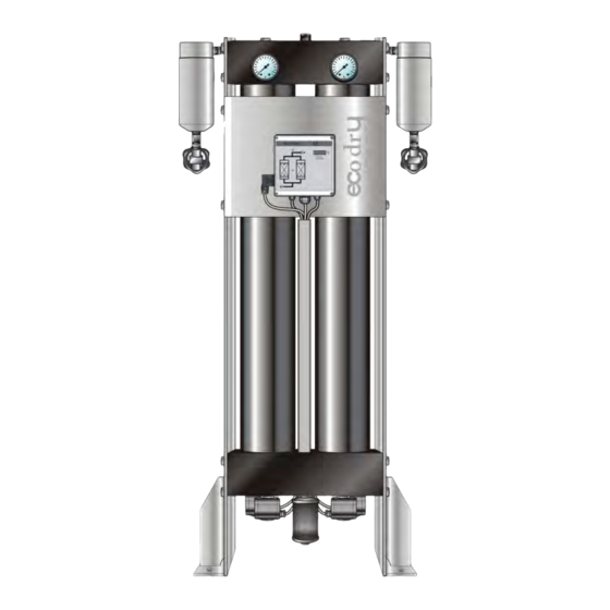
Summary drawing Technical product description Summary drawing Front view Compressed air inlet Compressed air outlet Downstream filter Vessel pressure gauge Check valve block Upstream filter Hand drain Control cabinet On/Off-Switch Power supply connector Vessel Solenoid valve block Upright stand profiles Muffler Solenoid valves Function description... - Page 15 Technical product description The stored humidity is then removed again from the drying agent and re- introduced into the ambient environment. To this end, the two vessels alternate between different operating modes. Whilst in one vessel, compressed air is de- humidified (adsorption), in the other vessel the humid drying agent is prepared for another charge (regeneration).
-
Page 16: Available Options
Available options Available options The following options are available for the dryer: Start-up device Auxiliary heater Bypass line Signalling contacts of control system Compressor synchronisation Dewpoint-sensing control Condensate drain pipe for preliminary and afterfilter ... - Page 17 Technical product description Dewpoint-sensing control With a dewpoint-sensing control system, you can operate the dryer in fixed or variable cycles. In the fixed cycle, switchover is effected after a fixed time period (usually after 10 minutes). In the variable cycle, the switchover is effected in relation to the dew point reached and the charging of the drying agent.
-
Page 18: Transportation, Installation And Storage
Information on transportation packaging Transportation, installation and storage Danger due to incorrect transportation! The dryer must be transported by authorized and qualified specialist personnel only. During transportation all applicable national regulations for accident prevention must be complied with. Otherwise there is a risk of personal injury. -
Page 19: Transporting And Installing The Dryer
Transportation, installation and storage Transporting and installing the dryer Requirements for the installation site The conditions at the installation site have a large influence on the functional capability of the dryer and the service life of the drying agent. In order to ensure a mode of operation, which is as continuous as possible, and low maintenance, the installation site must meet the following requirements: The installation site must be located within a building - protected against... -
Page 20: Installing And Anchoring
Installing and anchoring Installing and anchoring Installing ► Remove the packaging of the dryer. ► Screw the enclosed ring bolts into the drilled holes on the upper valve block. ► Attach suitable lifting gear to the ring bolts. ► Place the dryer at its installation site. Transport by crane Anchoring the dryer The upright stand profiles of the dryer are provided with four pre-drilled... - Page 21 Transportation, installation and storage In order to store the dryer proceed as follows: ► Take dryer out of operation as described on page 35. ► Ensure that the compressed air inlet valve installed by the owner, and the installed compressed air outlet valve installed by the owner, are both closed, and that the dryer is depressurised.
-
Page 22: Installation
Preconditions for installation Installation Only authorized and qualified specialist personnel may carry out work on pipes and electrical systems. As soon as the dryer has been set up at its installation location, you can install the compressed air infeed and outlet lines make the electrical connections. Preconditions for installation For a correct installation the following preconditions must be met on the part of the owner. -
Page 23: Connect Piping
Installation Connect piping In order to ensure that the dryer operates optimally, the dryer must be assembled into the compressed air system free of all stresses. ► Ensure before connection that all infeed and outfeed compressed air lines and valves are clean and undamaged. ►... -
Page 24: Installing The Electrical Connection
Installing the electrical connection Installing the electrical connection Warning against electrical voltage Only qualified specialist personnel may carry out work on the electrical system! Installing the supply cable The components of the dryer have been connected to the control cabinet at the factory. - Page 25 Installation Connecting the external signalling lines For compressor synchronisation The controller is fitted as standard with a digital input which makes the dryer regeneration dependent on operation of the compressor (switch S1 on the controller’s circuit board, see also figure below). If switch S1 is in the ON position, operation of the compressor and dryer regeneration run synchronously: When the compressor is stopped, the dryer regeneration also stops.
-
Page 26: Start-Up
Requirements for initial start-up Start-up Note: You can order the initial commissioning and start-up from the manufacturer and have your personnel trained by the manufacturer. For telephone number, see page 6. Carry out all prescribed tests and checks. Before start-up, ensure that no tools or other foreign parts have been left ... -
Page 27: Setting Times Of The Operating Phases
Start-up Setting times of the operating phases In its standard version the dryer is delivered with a time-dependent control system. The phase sequence occurs in a fixed cycle. With the optional dewpoint-sensing control, the dryer can also be operated at variable cycles (depending on the dewpoint). - Page 28 Overview of operating and control elements Display panel The display panel at the switchbox is equipped with LEDs (light emitting diodes) and a digital display, indicating the operating status of the dryer: Display panel at the switchbox LED Power (1) LED is on when dryer is switched on.
- Page 29 Start-up Display Explanation Default display: The figure to the left indicates the current processing step; the figure to the right shows the remaining time in seconds. In this example, step 2 is being completed, whereby there are 215 seconds remaining. After 8000 operating hours, "SEr."...
-
Page 30: Emergency Shutdown
Emergency shutdown Emergency shutdown In the event of an emergency, shut down the dryer as described on page 35. Start up dryer Warning against sudden air ejection! During expansion the pressure is released suddenly through the muffler: A loud expansion noise is caused which may damage your hearing. ... - Page 31 Start-up Open compressed air supply and switch on dryer For start-up, please proceed in the sequence shown here. ► Ensure that the compressed air inlet and outlet valves installed by the owner are closed (see installation example on page 23). ►...
-
Page 32: Changing Cycle Mode (Optional)
Changing cycle mode (optional) Operate dryer immediately in the compressed air system ► Ensure that the compressed air system downstream of the dryer is pressurised or that a start-up device (option, see page 16) was installed into the compressed air system directly downstream of the dryer. The importance of this increases with the size of the compressed air system downstream of the dryer. - Page 33 Start-up Which cycle modes can I choose? If the dryer is connected to a compressor synchronisation system and is equipped with the dewpoint-sensing control option, these two optional devices can only started together. The compressor synchronisation has thereby precedence over the dewpoint-sensing control. Compressor synchronisation (optional) If compressor synchronisation is enabled, the dryer can only be operated in conjunction with the compressor.
-
Page 34: Monitoring Dryer Operation
With dewpoint-sensing control (optional) Monitoring dryer operation The dryer operates fully automatically. However, you should carry out the regular checks described in the Chapter Maintenance and repair of the dryer. Warning against sudden air ejection! During expansion the pressure is released suddenly through the muffler: ... -
Page 35: Shutdown And Restart Dryer
Shutdown and restart dryer Shutdown and restart dryer In the following cases, the dryer must be fully shut down and depressurised: In the event of an emergency or malfunction For maintenance work For dismantling Risk of injury from escaping compressed air! Never remove any parts of the dryer, or manipulate the same in any way, as long as the unit is pressurised! Suddenly escaping compressed air might cause serious injuries. -
Page 36: If Work Is To Be Carried Out On The Electrical System
If work is to be carried out on the electrical system If work is to be carried out on the electrical system ► Depressurise and shut down the dryer, following the instructions in the above chapter. Risk of injury due to voltage-carrying parts! The electrical supply cable and external power lines are live even after the dryer is switched off and, in the event of body contact, may cause serious injury! Before carrying out any work on the electrical system, the... -
Page 37: Maintenance And Repair Of The Dryer
Maintenance and repair of the dryer Maintenance and repair of the dryer In order to allow maintenance work on the dryer to be carried out efficiently and without danger for maintenance personnel, you should comply with the following instructions. Notes on maintenance Warning! Maintenance tasks may be carried out only by authorized and qualified specialist personnel, and only with the plant in a switched off and... -
Page 38: Regular Maintenance Intervals
Regular maintenance intervals Regular maintenance intervals The table provides an overview of the maintenance work to be carried out. The following pages describe some of these tasks. Maintenance work requiring the dryer to be largely disassembled is not described. We recommend to have this work to be performed by authorised specialists. -
Page 39: Instructions For Use Of The Dongle
Maintenance and repair of the dryer When carrying out any maintenance work, comply with the following safety instructions: Danger! There is a very considerable risk of personal injury, when carrying out work on the activated and pressurised dryer. Before commencing any maintenance tasks always shut down the dryer as described on page 35! Warning against electrical voltage! Only qualified specialist personnel may carry out work on the electrical... -
Page 40: Maintenance Work To Be Completed Every 12 Months
Maintenance work to be completed every 12 months Carry out visual and function check on the complete dryer ► Check dryer for external damage or unusual noise generation. ► Duly eliminate any defects found. If message SEr. is displayed, a routine service must be completed: ►... -
Page 41: Maintenance Work To Be Completed Every 24 Months
Maintenance and repair of the dryer Renew dewpoint sensor In order to ensure accurate dewpoint measuring, we recommend renew the dewpoint sensor annually. Dewpoint sensor Warning! The dew point sensor is a sensitive measuring device. It can be damaged if subjected to forceful vibrations or shocks. Therefore, please handle the dew point sensor with great care at all times. -
Page 42: Identify And Eliminate Faults
Summary of faults Identify and eliminate faults The following table provides information on what designatory abbreviations are to be used for the various components. These designations are also found in the technical documentation. Used abbreviation Component Pressure gauge Y1–Y2 Main valves (Solenoid valves) Y3–Y4 Expansion valve (Solenoid valves) Pressure build-up valve (Solenoid valve) - Page 43 Identify and eliminate faults Fault Possible cause Remedy Insufficient regeneration gas Check function of valve Y3/Y4 and muffler; replace filter element of muffler, if necessary. Pressure in vessel Excessive differential pressure at Check differential pressure at the upstream ...
- Page 44 Summary of faults With dewpoint-sensing control (optional) Fault code Description of fault Possible cause Remedy Upper measuring range Drying capacity See instructions for commissioning. limit exceeded exceeded. If the drying agent is wet, replace it. Error in programme. Restart programme. ...
-
Page 45: Index
Index Index Dongle use ............... 39 Dryer Abbreviation maintenance interval ..........38 components ............42 drying agent Address, manufacturer ..........6 maintenance interval ..........38 air ejection service life ............41 hazard ..............10 Drying agent Auxiliary heater ............16 charging ............... - Page 46 Maintenance differential pressure ..........40 Regeneration, explanation ........15 Muffler ..............40 Regulations for accident prevention ......18 replacement of filter element ........40 Replacement parts ..........13, 37 sensor ..............41 Restart Maintenance contract ..........38 pressure conditions ..........36 Maintenance, danger warnings ......37, 39 Maintenence back pressure ............40 Media...
-
Page 47: Annex With Technical Documentation
Annex with technical documentation Annex with technical documentation This annex comprises the following information and technical documentation: Technical data Replacement and wear parts list Logic control diagram Flow diagram Dimensional drawing HDK-MT350_EN_04... -
Page 48: Technical Data
Technical data Technical data Amount of Capacity* Length Height Width Weight, drying agent per approx. dryer Type 100 bar 1015 HDK-MT 4-100 1025 HDK-MT 6-100 1035 HDK-MT 10-100 1045 HDK–MT 15-100 11,6 1245 HDK-MT 20-100 15,6 1445 HDK-MT 25-100 19,4 1645 HDK–MT 30-100 26,4... - Page 49 Annex with technical documentation Amount of Capacity* Length Height Width Weight, drying agent per approx. dryer Type 350 bar 1015 HDK-MT 4-350 1025 HDK-MT 6-350 1035 HDK-MT 10-350 1045 HDK–MT 15-350 1245 HDK-MT 20-350 1445 HDK-MT 25-350 1645 11,2 HDK–MT 30-350 1645 17,8 HDK–MT 40-350...
-
Page 50: Replacement And Wear Parts List
Replacement and wear parts list Replacement and wear parts list For both the 12 month and 24 month maintenance, you can order complete service kits from the manufacturer with all the necessary replacement parts. Mufflers and filter elements must always be ordered separately from the service kit. Note: When exchange or replacement parts are ordered, always state the dryer type and the build no. - Page 51 Annex with technical documentation Additional Spare parts Designation Order number Muffler SDD-15/600/AL Filter elements s. enclosed Filter manual HDK-MT350_EN_04...
-
Page 52: Logic Control Diagram
Logic control diagram Logic control diagram Adsorption in B1 and regeneration in B2 HDK-MT350_EN_04... - Page 53 Annex with technical documentation Regeneration in B1 and adsorption in B2 HDK-MT350_EN_04...
-
Page 54: Flow Diagram
Flow diagram Flow diagram Item Designation Item Designation Vessel Pressure gauge Upstream filter Check valves Downstream filter Solenoid valves Solid filter Control cabinet Lower valve block Muffler Upper valve block Pressure maintaining valve HDK-MT350_EN_04... -
Page 55: Dimensional Drawing
Annex with technical documentation Dimensional drawing Type HDK-MT 100/250/350 bar Dimensions 15/... 20/... 25/... 30/... 40/... 50/... 60/... 70/... (mm) 1045 1245 1445 1645 1645 1845 2045 2145 G 3/4 Connection HDK-MT350_EN_04...