
Related Manuals for Emerson AMS EZ1000


Summary of Contents for Emerson AMS EZ1000
- Page 1 Operating Manual MHM-97884, Rev 1.01 February 2019 ™ Machinery Health Sensor EZ 1000, Converter for Eddy Current Sensors...
- Page 2 Copyright No part of this publication may be reproduced, transmitted, transcribed, stored in a retrieval system, or translated into any language in any form by any means without the written permission of WayCon. Disclaimer This manual is provided for informational purposes. WAYCON MAKES NO WARRANTY OF ANY KIND WITH REGARD TO THIS MATERIAL, INCLUDING, BUT NOT LIMITED TO, THE IMPLIED WARRANTIES OF MERCHANTABILITY AND FITNESS FOR A PARTICULAR PURPOSE.
- Page 3 Nota referente à instalação de cadeias de agrimensor em ambientes potencialmente explosivos Caso a cadeia de agrimensor deva ser instalada em um ambiente potencialmente explosivo, é imprescindível observar e cumprir as indicações de instalação das instruções de serviço. Caso tenha dificuldades idiomáticas, queira entrar em contato com a firma produtora, esta poderá...
- Page 4 Remarque concernant l’installation des chaînes de mesure dans un environnement présentant un risque d’explosion Si la chaîne de mesure doit être installée dans un environnement présentant un risque d’explosion, il est impératif de veiller à respecter les consignes d’installation contenues dans les instructions de service. S’il devait ce faisant surgir des problèmes linguistiques, veuillez vous adresser à...
- Page 5 Poznámka k instalaci mĕřicích řetězců v prostředí s nebezpečím výbuchu. Když má být měřicí řetězec (sestávající z čidla a konvertoru) instalován v prostŕedí s nebezpečím výbuchu, tak je třeba respektovat instalační pokyny, které jsou součástí návodu k upotřebení. Kdyby při tom došlo k jazykovým potížím, tak prosíme kontaktujte výrobní...
-
Page 6: Table Of Contents
Contents Contents General ............................1 Chapter 1 Using this manual ........................... 1 Symbols ..............................2 Liability and guarantee ........................... 2 Incoming goods inspection ........................2 Technical support ........................... 3 Storage and transport ..........................3 Disposal of the device ..........................3 China RoHS Compliance ......................... - Page 7 Contents Chapter 8 Configuration ..........................43 General configuration procedure ......................43 Offline configuration overview .................... 43 8.1.1 8.1.1.1 Send a saved configuration file to the EZ 1000 ............44 Online configuration overview ..................... 45 8.1.2 Start of an offline configuration ......................46 Start of an online configuration ......................
-
Page 8: Chapter 1 General
General General Topics covered in this chapter: • Using this manual • Symbols • Liability and guarantee • Incoming goods inspection • Technical support • Storage and transport Disposal of the device • • China RoHS Compliance Installation awareness • Using this manual This manual contains information concerning the use of the device. -
Page 9: Symbols
General Symbols Note This symbol marks passages that contain important information. CAUTION! This symbol marks operations that can lead to malfunctions or faulty measurements, but will not damage the device. DANGER! A danger indicates actions that can lead to property damage or personal injury. According to IEC 61010, this symbol means that the documentation of the device must be completely read and understood before installing and commissioning of the device. -
Page 10: Technical Support
General Technical support You may need to ship this product for return, replacement, or repair to an WayCon Product Service Center. Before shipping this product, contact WayCon Product Support to obtain a Return Materials Authorization (RMA) number and receive additional instructions. Product Support WayCon provides a variety of ways to reach your Product Support team to get the answers you need when you need them:... -
Page 11: China Rohs Compliance
General Note Environmental hazards! Electrical waste and electronic components are subject to treatment as special waste and may only be disposed by approved specialized companies. China RoHS Compliance Our products manufactured later than June 30, 2016 and those which are sold in the People's Republic of China are marked with one of the following two logos to indicate the Environmental Friendly Use Period in which it can be used safely under normal operating conditions. -
Page 12: Chapter 2 Safety Instructions
Safety instructions Safety instructions Topics covered in this chapter: Using the device • Owner's responsibility • Radio interference • • ESD safety To ensure safe operation, carefully observe all instructions in this manual. The correct and safe use of this device requires that operating and service personnel both understand and comply with general safety guidelines and observe the special safety comments listed in this manual. -
Page 13: Radio Interference
Safety instructions DANGER! If device tests have to be completed during operation or if the device has to be replaced or decommissioned, it will impair the machine protection and may cause the machine to shut down. Make sure to deactivate machine protection before starting such work, and reactivate it after work has been completed. -
Page 14: Application And Design
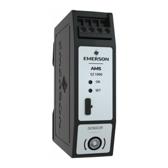
Application and design Application and design Topics covered in this chapter: • Application • Design Application The EZ 1000 is a signal converter for different types of eddy current sensors. The converter is designed for the connection of eddy current sensors of the EZ 10xx series and a selection from third party sensors: •... - Page 15 Application and design Figure 3-1: EZ 1000 Two screw terminals for -24 V DC supply voltage. Two screw terminals for sensor output signal (range: -2 V to -18 V) Green Channel OK LED (see Table 3-1) Button for offline calibration (Easy calibration) without Machine Studio and for Firmware update Configuration interface (USB 2.0 Micro-B socket with cover) Sensor socket with external thread for sensor connection Build-in spring DIN rail clip...
- Page 16 Application and design Table 3-1: LED blinking pattern (continued) Event Blinking pattern Sequence Automatic calibration Unlimited fast flashing (5 Hz) – until power off/ with Machine Studio – on the EZ 1000 failure detected Firmware update Slow flashing (1 Hz) while waiting for button press Steady light while erasing and writing the firmware...
-
Page 17: Chapter 4 Function Principle
Function principle Function principle The measuring coil of the eddy current sensor (for example EZ 1050 or EZ 1080) is connected to an oscillator circuit in the converter through a shielded connection cable. The oscillator circuit generates a high-frequency signal resulting in a high-frequency magnetic field around the tip of the eddy current probe. -
Page 18: Sensor Supervision
Function principle Note If installing a calibrated measuring chain at a different measuring point, ensure that the target material of this point is the same as of the previous point. Otherwise, recalibrate the converter on the new target material. Sensor supervision The EZ 1000 checks the connected sensor by supervising the signal voltage. - Page 19 Function principle Table 4-1: Causes for sensor not OK indication (continued) Cause Possible reasons Solution Sensor cable break Open connector. Check the sensor cable and connections. Replace Damaged sensor cable. a defective sensor. Check cable path to avoid further damages. Sensor head damage Permissible environmental temperature Replace the defective...
-
Page 20: Installation And Commissioning
Installation and commissioning Installation and commissioning Topics covered in this chapter: • CSA - General safety • Mounting • Hints for installation and connection Adjustment of measuring chains at the machine • • Mutual influences of two measuring chains CSA - General safety Equipment to be installed within another enclosure which provides the safety aspects and protects the operator from hazards and is suitable for outdoor environment conditions. - Page 21 Installation and commissioning Figure 5-1: Minimum required mounting space Figure 5-2. Snap the EZ 1000 onto the DIN rail as shown in [16]...
-
Page 22: Hints For Installation And Connection
Installation and commissioning Figure 5-2: DIN rail mounting EZ 1000 DIN rail type NS 35/7.5 Minimum required space on DIN rail: 26 mm Hints for installation and connection To ensure the electromagnetic compatibility of the eddy current measuring chain, WayCon recommends using a double shielded twisted pair cable for connecting the EZ 1000 converter to the measuring amplifier, for example to an A6500-UM Universal Measurement Card of the AMS 6500 ATG system. - Page 23 Installation and commissioning measuring amplifier directly at the cable inlet of the control cubicle. Moreover, connect the outer cable shield to protective earth as often as possible, for example, at every intermediate distribution frame or cable gland. A higher electromagnetic compatibility can be achieved by connecting the cable shield to protective ground at either end of the cable –...
-
Page 24: Connections And Wiring
Installation and commissioning • Install measuring cables according to general standards for measuring and control cables. • If possible, install cables in metallic cable channels or tubes. • Observe that the measuring cables are arranged orthogonally. 5.3.1 Connections and wiring The EZ 1000 is equipped with four screw terminals for power supply connection and output signal connection, and a LEMO socket for the connection of one eddy current Table 5-1... - Page 25 Installation and commissioning Figure 5-4: Connection example Cabinet Rear view of a slot of an AMS 6500 ATG backplane (x = slot number). Double shielded and twisted pair cable, for example LiYCY-CY 2x2x0.25mm² Junction box Field housing with EZ 1000 Shield earth Protection earth Screw terminal for power supply: -24 V...
-
Page 26: Sensor Connection
Installation and commissioning Sensor connection The following sensor types can be connected. • EZ 105x and EZ 108x • Bently Nevada 3300 XL 8 mm Proximity Probes 33010x. The sensor adapter EZ1900-003-ADAP-2 is required for the connection of 33010x probes. Figure 5-5: Sensor adapter EZ 1900-003-ADAP-2 A. -
Page 27: Adjustment Of Measuring Chains At The Machine
Installation and commissioning First the blue shrink sleeve and then the black shrink sleeve. Close the connection. Move the black shrink sleeve over the closed connection. Plug and socket must be completely covered by the shrink sleeve. Ensure that the shrink sleeve evenly overlaps plug and socket. Use a hot air gun to evenly shrink the sleeve. - Page 28 Installation and commissioning For sensors with an extension cable, WayCon recommends removing the extension cable to avoid twisting the cable during mounting and turning the sensor. Reconnect the extension cable before measuring the output voltage for the fine adjustment. • For measuring shaft vibrations, it is sufficient to adjust the sensor to an output Figure 5-6.
-
Page 29: Mutual Influences Of Two Measuring Chains
Installation and commissioning Figure 5-7: Characteristic curve - static A. Characteristic curve -2 V to -18 V B. Initial air gap C. Working range (-x to +x) D. Minimum distance E. Center point (zero point) F. Maximum distance G. Nominal distance H. - Page 30 Installation and commissioning • Shaft vibration measurement with two sensors in X-Y arrangement (for example: two EZ 108x sensors, mounted in a 90° angle at a shaft with ≤100 mm diameter). • Shaft displacement measurement with Tandem application. • Shaft displacement measurement with Cone or Double Cone application. In this case, the oscillator frequency of one of the converters must be slightly shifted.
-
Page 31: Hazardous Location Installation
Hazardous location installation Hazardous location installation Topics covered in this chapter: • General installation requirements • Installation requirements – intrinsic safe • Installation requirements – non-sparking Installation of the sensors • • CSA – Special conditions of safe use Technical data, explosion protection •... -
Page 32: Installation Requirements - Intrinsic Safe
Hazardous location installation • For the maximum environmental temperature of the EZ 10xx and PR 642x sensors approved for temperature classes T2, T4, and T6 see Table 6-5. • Install the EZ 1000 according to the control drawing CDG 5800-00182. •... - Page 33 Hazardous location installation • Solely connect the EZ 1000 converter to SELV/PELV electrical circuits to meet the requirements of U = 60 V for the explosion protection. This is valid for both, the supply (-24 V/┴) and the signal (┴/OUT) terminals. •...
-
Page 34: Installation Of The Sensors
Hazardous location installation Figure 6-1: Minimum dimension of the field housing cross section • Ensure that the cable glands match the diameter of the used cables. Diameter EZ 105x, EZ 108x, and PR 642x sensor cable: 2.65 to 2.90 mm Diameter of the supply and signal cables are variable and must be observed. -
Page 35: Csa - Special Conditions Of Safe Use
Hazardous location installation During the sensor mounting, give particular attention to the grounding of its metal housing. The transition resistance of the sensor housing to the protective earth must not exceed 1 MOhm. CSA – Special conditions of safe use Note Installation in protection class Ex i (intrinsically safe) or Ex nA (non-sparking): •... - Page 36 Hazardous location installation Table 6-1: cCSAus (continued) T6 -35°C ≤ Ta ≤ 50°C T4 -35°C ≤ Ta ≤ 80°C T2 -35°C ≤ Ta ≤ 80°C Standards CSA E60079-15 (Zone 2, Type n) UL 60079-15-02 2002 (Protection n) CSA approval number CSA 18.70093801 Table 6-2: ATEX/IECEx Intrinsically safe (Ex ia)
- Page 37 Hazardous location installation Table 6-3: General Electrical data Output and supply circuit With explosion protection class Intrinsically safe, only for connection to certified intrinsically safe circuits with the following maximum values. -24 V / ┴/ ┴ / Out terminals Open-circuit voltage = -28 V ΣI Sum of short- circuit...
- Page 38 Hazardous location installation Table 6-4: Capacities and inductances of sensors including connection cable and extension cable (continued) Sensor Capacity (C Inductance (L Sensor Sensor EZ1900-003-ADAP-1 Adapter +39 pF negligible cable for connection of PR 642x sensors EZ1900-003-ADAP-2 Adapter +39 pF negligible cable for connection of BN 33010x sensors...
-
Page 39: Control Drawings
Control drawings [35]... - Page 40 [36]...
- Page 41 SPECIAL CONDITION OF SAFE USE: • THE INFLUENCE OF POWER DISSIPATION OTHER DEVICES PLACED BESIDE THE CONVERTER BEEN TAKEN INTO ACCOUNT WITHREGARD TEMPERATURE RISE CONVERTERS'S AMBIENT TEMPERATURE. • THE APPARATUS HAS BE INSTALLED USED SUCH A WAY THAT ELECTROSTATIC CHARGING FROM OPERATION, MAINTENANCE...
-
Page 42: Revision History
Hazardous location installation – application notes Revision history Version Date Remarks/Changes 26. January 2018 Initial version 3. April 2018 Control Drawing update 10. July 2018 Grammar corrections 1. August 2018 Control Drawing update and addition to chapter 6.2 [38]... -
Page 43: Hazardous Location Installation - Application Notes
Hazardous location installation – application notes Hazardous location installation – application notes Topics covered in this chapter: • Mark the converter as "once used without safety barrier" EZ 1000 with AMS 6500 • This chapter contains additional information about the installation of the EZ 1000 converter within hazardous areas. -
Page 44: Ez 1000 With Ams 6500
Hazardous location installation – application notes Figure 7-1: Removable sticker Removable sticker The inscription below the sticker reads: Only non intrinsically safe use. EZ 1000 with AMS 6500 Use an additional diode when connecting an EZ 1000 converter through safety barriers to cards for eddy current sensors of the AMS 6500 system. - Page 45 Hazardous location installation – application notes Figure 7-2: Connection diagram – additional diode Sensor, such as EZ 105x or EZ 108x. EZ 1000 Converter Safety barrier, supply circuit (Stahl 9001/00-280/085/101) Safety barrier, measuring circuit (Stahl 9001/00-280/020/101) Two level terminal with diode. The diode is only necessary at supply voltages higher than -26 V. AMS 6500 card for eddy current sensors, such as A6110, A6210, or A6312.
-
Page 46: Chapter 8 Configuration
Configuration Configuration Topics covered in this chapter: • General configuration procedure • Start of an offline configuration • Start of an online configuration • Configuration of an already existing converter • Configuration editor and parameters Send and Reload a configuration •... -
Page 47: Send A Saved Configuration File To The Ez 1000
Configuration The calibration procedure requires an online connection to the converter. Save the configuration (Configuration editor > File > Save as). When you connect to the EZ 1000, load the saved configuration file to the converter, and complete the calibration process (see Send a saved configuration file to the EZ 1000). -
Page 48: Online Configuration Overview
Configuration 8.1.2 Online configuration overview Switch on the power supply of the converter, if not already done. Connect the converter to the configuration computer by using the USB connection. Figure 8-2: Connection – computer to USB interface A. USB socket at the computer with Machine Studio installed. B. -
Page 49: Start Of An Offline Configuration
Configuration Start of an offline configuration Select Workspace in the left part of the main view, then click Item > Converter > EZ 1000 converter. Figure 8-3: Start new device configuration A. Item EZ 1000 converter B. Workspace The EZ 1000 converter is added to the list below Workspace. Select an EZ 1000 from the Workspace list, and click Configure. -
Page 50: Start Of An Online Configuration
Configuration Figure 8-5: New Configuration dialog Select EZ 1000, and click Create Configuration to open the configuration editor. Section 8.5 for parameter description and settings. Note The calibration requires an online connection to the EZ 1000 converter. Move the converter configuration from Workspace by drag and drop to an already connected converter below Network. -
Page 51: Configuration Of An Already Existing Converter
Configuration Figure 8-6: Select an EZ 1000 for online configuration A. Button Configure for opening the configuration editor. B. Selected EZ 1000 converter. If the selected EZ 1000 is not configured, the New Configuration dialog opens (see Section 8.2). Otherwise, the configuration editor opens directly. Section 8.5 for parameter description and settings. -
Page 52: Ribbon Command Bar
Configuration Figure 8-7: Configuration Ribbon command bar Configuration dialog Converter name with type of used interface in brackets List of configuration pages 8.5.1 Ribbon command bar New configuration Click New configuration to start a new configuration with default parameters. Figure 8-8: Button New configuration Send &... - Page 53 Configuration The parameters Point Id, Serial number of the sensor, and Serial number of the cable on tab Input. The parameter Output sensitivity on tab Measurement. Major changes are: The parameters Sensor and Extension cable on the Input tab. All parameters on the Measurement tab except parameter Output sensitivity. Figure 8-9: Button Send &...
- Page 54 Configuration Figure 8-11: Button Reset to factory default This command requires an online connection to the converter. CAUTION! The preset configuration on the converter including the calibration data will be deleted and replaced by the default configuration. Compare Click Compare to show differences between the configuration on the converter and in the memory of the used Laptop or PC.
- Page 55 Configuration The Settings window opens. Click the buttons with the dotted line within the Report settings area to browse for logos. Logos with file format png or jpg can be selected. Click OK to confirm your settings. The window closes. Open the configuration editor, and go back to the report.
- Page 56 Configuration Figure 8-16: History The right part of Figure 8-16 shows the configuration history. The individual files are marked with date, time, and type: Draft Config • A saved preliminary configuration file which has not yet been sent to the converter. Running Config •...
-
Page 57: Basic
Configuration Button Close configuration Figure 8-18: 8.5.2 Basic Enter general machine and plant information. Figure 8-19: Basic Name Enter the converter name or a short description of the measurement. Machine Enter the machine designation. Area Enter a name or a short description of the area where the machine is located. -
Page 58: Measurement
Configuration Figure 8-20: Input Point Id Enter the point ID of the measuring point where the sensor is installed. Sensor Click the button behind the display field to open the selection dialog for the sensor. The dialog lists all eddy current sensors compatible with EZ 1000. - Page 59 Configuration Extended The standard measuring range of several eddy current sensors can be range extended. Use this list field to select a factor for the range extension. The available factors depend on the selected sensor (see Input > Sensor). The factor standard measuring range is multiplied with the selected factor.
-
Page 60: Calibration
Configuration 8.5.5 Calibration Enter the calibration parameters or start the automatic calibration. A wizard guides you through the calibration process. The calibration dialog depends on the selected calibration method. Note The sensor data is sent to the EZ 1000 at the beginning of the calibration methods Automatic calibration or Multipoint calibration. -
Page 61: Manual Calibration - Guided Process
Configuration Use this method for third party sensors, for a configuration with activated detuning (Measurement > Detune frequency), or to recalibrate an already calibrated measuring chain. Depending on the selected sensor (Input > Sensor), a calibration method is recommended. The recommended method is marked with (Recommended). - Page 62 Configuration Sensor gain Enter the sensor gain. See Figure 8-24 where to find the data if using an EZ 105x or an EZ 108x sensor. The abbreviation for the sensor gain on the label is SG. Figure 8-24: Location sensor data A.
-
Page 63: Automatic Calibration - Guided Process
Configuration The sending progress is displayed. Click Next. Click Finish to exit the wizard. Click Close configuration to exit the configuration editor. Do not click Send & close. Automatic calibration – guided process The process steps after the selection of the calibration method are described below. Note Wait 60 seconds after powering up the EZ 1000 converter or after a firmware update before starting the automatic calibration. - Page 64 Configuration • USB cable • Sensor is not installed in the machine. The start point for the calibration – maximum gap between measuring target and sensor including the initial air gap – depends on the selected sensor type. Table 8-1 lists the start points depending on the sensor and the configured extended range factor (Measurement >...
- Page 65 Configuration Figure 8-26: Dialog – sensor temperature Mount the sensor into the calibration gauge. With the micrometer screw, adjust the distance between measuring object and sensor head to the maximum gap stated in row B of Figure 8-27. The distances in column [mm] can not be changed here and depend on the selected sensor and the extended range factor (see Table...
- Page 66 Configuration Figure 8-27: Multipoint calibration A. Buttons for measurement of converter output voltage. B. Calibration point for the end of the measuring range (greatest distance between sensor and measuring object). C. Calibration point for the center of the measuring range. D.
-
Page 67: Send And Reload A Configuration
Configuration The measured voltage (approximately -10 V) is entered into the related field of column [V]. With the micrometer screw, adjust the distance between measuring object and Figure 8-27. sensor head to the minimum gap stated in row D of Click the measuring button in row D to measure the output voltage of the converter. -
Page 68: Offline (Easy) Calibration
Configuration Machine Studio will automatically establish an online connection to the EZ 1000 as soon as there is a physical connection through the USB port. Click Send & close in the ribbon command bar to send the configuration to the EZ 1000. - Page 69 Configuration Prerequisites • -24 V DC power supply, if the converter is not supplied by a measuring amplifiers such as an A6500-UM Universal Measuring Card. • EZ 1000 with factory default settings. • EZ 108x sensor with 5 m or 10 m sensor cable. •...
- Page 70 Configuration Figure 8-28: LED and button location A. Green LED (OK) B. Calibration button (SET) To complete the calibration, release the button. The calibration process starts and the double flashing of the LED continues for five seconds. The calibration is finished when the LED stops double flashing, and the light is constantly green.
-
Page 71: Components Database - Add A New Target Material
For additional target material data, go to the Emerson download portal. If the required material data is not available on the portal, contact Product Support. If required, Product Support will ask you to send in a sample of the target material to determine the material data. - Page 72 Configuration The new target material is added to the components database and available for the converter configuration. Related information Technical support [69]...
-
Page 73: Chapter 9 Online View
Online View Online View Topics covered in this chapter: • Overview • Details Live data • After connecting Machine Studio with an EZ 1000 converter, the Online View of the converter appears. Figure 9-1: Online View - overview Connected devices in the device tree List of connected EZ 1000 converters A few details of the converter selected from the list. -
Page 74: Overview
Online View Figure 9-2: Online View Overview Overview contains several graphic objects to provide an overview about the converter status. Channel OK This graphic object displays the converter state. Figure 9-3: Channel OK – expanded object • A fault-free converter is indicated with a checkmark within a green solid circle •... - Page 75 Online View Click on Channel OK to expand the object, and get more information about the converter state. Table 9-1: Flags Channel OK Flag Meaning Action Channel OK No fault detected. Sensor or converter fault Check sensor and converter including detected.
- Page 76 Online View • A faulty calibration is indicated with a yellow warning triangle Click on Calibration state to expand the object. Table 9-2: Calibration state flags Flag Meaning Action Calibration Calibration is OK. state No calibration. Calibrate the converter. The Easy calibration or Repeat the Easy or Automatic Automatic calibration is not calibration.
-
Page 77: Details
Online View Details Details provides more detailed status information of the converter. The graphic objects Converter health, Channel OK, Voltage output, and Calibration state are described in Section 9.1. Figure 9-7: Details Service This graphic object displays temperatures measured by the internal temperature sensor. Figure 9-8: Service Curr. - Page 78 Online View Figure 9-9: Measurement Target material Material of the measuring object entered in the configuration (see Section 8.5.4). Detuning Displays the selected detuning level (see Section 8.5.4). Extended range Configured factor for the measuring range extension (see factor Section 8.5.4).
- Page 79 Online View Figure 9-11: Sensor Type Configured sensor type. Cable length Cable length of the configured sensor type. Serial Serial number of the sensor entered in the configuration (see Section 8.5.3). Extension cable This graphic object displays general extension cable data. Figure 9-12: Extension cable Type Configured extension cable type.
-
Page 80: Live Data
Online View Factory def.: Converter has the factory default configuration • (delivery state). User def.: Converter has a user defined configuration. • Cal. type Indicates the calibration type. Not available: Calibration state is not available. • Auto: The converter has been calibrated with the Automatic •... - Page 81 Online View Figure 9-14: Live data Each diagram has several controlling elements: Region Use this function to enlarge an interesting part of the diagram. zoom Click the icon to activate the function. The button is colored light blue if the function is activated. Place the mouse cursor close to the area of interest.
- Page 82 Online View Move the view to the desired position. Release the mouse button to place the view at that point. Right-click somewhere on the diagram to reset the view change. Zoom in Use this function to stepwise enlarge the diagram view at mouse position. Click the icon to activate the function.
-
Page 83: Maintenance, Fault Finding, And Repair
Maintenance, fault finding, and repair Maintenance, fault finding, and repair Topics covered in this chapter: • Maintenance • Hints for fault finding • Replace an EZ 1000 • Replace a sensor Linearity check • • Firmware update 10.1 Maintenance During operation, the EZ 1000 converter does not require any maintenance. 10.2 Hints for fault finding CAUTION! -
Page 84: Replace An Ez 1000
Maintenance, fault finding, and repair Table 10-1: Meaning of converter output voltages (continued) Converter output voltage Meaning / Error No supply voltage. Output voltage range is not Converter is not calibrated on the connected sensor. properly scaled on the measuring range of the connected sensor. -
Page 85: Replace A Sensor
Maintenance, fault finding, and repair g. Go back to the editor and close it. Do not close Machine Studio. h. Switch off the power supply. Disconnect all wires from the EZ 1000 including sensor and USB cable. Remove the EZ 1000 from the mounting rail. Install the new EZ 1000. -
Page 86: Linearity Check
Maintenance, fault finding, and repair Connect the new sensor to the EZ 1000. Check the EZ 1000 configuration. Does the current configuration meets the requirements of the new sensor? Calibrate the EZ 1000 and the new sensor. Section 8.5.5 Section 8.7 for details. -
Page 87: Firmware Update
Maintenance, fault finding, and repair Adjust the voltage steps -12 V, -14 V, -16V, and -18 V as shown in Figure 10-1 with the calibration gauge, and check the distance with the micrometer screw of the gauge. Continue the check with the voltage steps -8 V, -6 V, -4 V, and -2 V, and check the distance. - Page 88 Maintenance, fault finding, and repair Prerequisites Ensure that the EZ 1000 to be updated is powered and the following items are available: • PC or Laptop with the latest version of Machine Studio installed. • USB cable with Type-A and micro-USB B plug •...
- Page 89 Maintenance, fault finding, and repair Figure 10-3: Update dialog Follow the instructions on the screen. Do not remove the USB cable during the update process. After the successful firmware update, the EZ 1000 restarts and the LED switches to a steady light –...
-
Page 90: Chapter 11 Technical Data
Technical data Technical data Topics covered in this chapter: • Input Supply • • Output • Errors and tolerances Only specifications with indicated tolerances or limit values are required. Data without tolerances or without error limits are informative data and not guaranteed. Technology is under constant development, and specifications are subject to change without notice. -
Page 91: Output
Technical data 11.3 Output Short-circuit prove Nominal output voltage range -2 V to -18 V Limit range -1.1 V to -21.6 V Nominal frequency range 0 to 20 kHz (-3 dB) without cable capacity 11.4 Errors and tolerances 11.4.1 EZ 1000 with EZ 105x Typical accuracy of the standard measuring chain following API 670 consisting of EZ 105x- xx-xx-010, EZ 190x-040, and EZ 1000 with standard target material 42CrMo4 (AISI 4140) and calibration methods Manual, Automatic, or Multipoint:... - Page 92 Technical data • No ambient temperature change of EZ 1000 during 1 hour before measurement, power and sensor connected to EZ 1000 for at least 10 minutes before measurement and calibration. • WayCon reference target material is 42CrMo4 (AISI 4140), unless otherwise stated. Note For measurements that require a higher measuring accuracy, factory calibrated measuring chains are available.
-
Page 93: Ez 1000 With Ez 108X
Technical data Table 11-2: Additional inaccuracies – DSL (continued) Additional Additional Measurement Measurement Inaccuracy (DSL), Inaccuracy (DSL), Parameter Test range Operating range Remarks Extended measuring range: 2.0 mm (Extended range factor: 2.0) Manual calibration 3.75% 4.0% Automatic calibration 3.75% 4.0% Multipoint calibration 0.5% 1.0%... - Page 94 Technical data • First meter of EZ 108x at temperature of EZ 108x. • No ambient temperature change of EZ 1000 during 1 hour before measurement, power and sensor connected to EZ 1000 for at least 10 minutes before measurement and calibration. •...
- Page 95 Technical data Table 11-4: Additional inaccuracies – DSL (continued) Additional Additional Measurement Measurement Inaccuracy (DSL), Inaccuracy (DSL), Parameter Test range Operating range Remarks Detune 1 / 2 0.75% 1.25% Only possible with multipoint calibration [94]...
-
Page 96: Index
Index Index Adjustment Housing Basic Influence Input Installation Cable Length Type Calibration Linearity check 2-Point Automatic Manual Machine Studio 7, 43, 64 Calibration state Maximum torque Channel OK 12, 72 Measurement Close editor Measurement dynamic Commissioning Measurement static Compare Measuring chain Component database Minimum distance Configuration editor... - Page 97 Index Sensitivity Sensor Frequency offset Voltage output Gain Offset Sensor supervision Sensor types Wire cross-section Show History/Draft Wizard Shrinkage tube Space Target material 11, 56, 68 Technical support [98]...
- Page 98 Index The contents of this publication are presented for informational purposes only, and while WayCon Positionsmesstechnik GmbH every effort has been made to ensure their accuracy, they are not to be construed as Mehlbeerenstr. 4 warranties or guarantees, express or implied, regarding the products or services described 82024 Taufkirchen herein or their use or applicability.