Quick Links
Introduction
Specifications
Receiving, Unpacking and
Inspection
Description of Operation
Chapter 1
Manual Objectives
. . . . . . . . . . . . . . . . . . . . . . . . . . . . . . . . . . . . . . . . .
1391 Series D
. . . . . . . . . . . . . . . . . . . . . . . . . . . . . . . . . . . . . . . . . . . . .
General Precautions
. . . . . . . . . . . . . . . . . . . . . . . . . . . . . . . . . . . . . . . .
Controller Description
. . . . . . . . . . . . . . . . . . . . . . . . . . . . . . . . . . . . . .
Standard Features
. . . . . . . . . . . . . . . . . . . . . . . . . . . . . . . . . . . . . . . . . .
Options/Modifications
. . . . . . . . . . . . . . . . . . . . . . . . . . . . . . . . . . . . . .
Controller Layout
. . . . . . . . . . . . . . . . . . . . . . . . . . . . . . . . . . . . . . . . . .
Chapter 2
Chapter Objectives
. . . . . . . . . . . . . . . . . . . . . . . . . . . . . . . . . . . . . . . . .
Controller Specifications
Environmental Specifications
Controller Power Dissipation
Transformer Power Dissipation
Chapter 3
Chapter Objectives
. . . . . . . . . . . . . . . . . . . . . . . . . . . . . . . . . . . . . . . . .
Receiving
. . . . . . . . . . . . . . . . . . . . . . . . . . . . . . . . . . . . . . . . . . . . . . . .
Unpacking
. . . . . . . . . . . . . . . . . . . . . . . . . . . . . . . . . . . . . . . . . . . . . . .
Inspection
. . . . . . . . . . . . . . . . . . . . . . . . . . . . . . . . . . . . . . . . . . . . . . . .
Storing
. . . . . . . . . . . . . . . . . . . . . . . . . . . . . . . . . . . . . . . . . . . . . . . . . .
Chapter 4
Chapter Objectives
. . . . . . . . . . . . . . . . . . . . . . . . . . . . . . . . . . . . . . . . .
General
. . . . . . . . . . . . . . . . . . . . . . . . . . . . . . . . . . . . . . . . . . . . . . . . . .
300V DC Power Bus Supply
PWM Operation
. . . . . . . . . . . . . . . . . . . . . . . . . . . . . . . . . . . . . . . . . . .
Shunt Regulator Operation
Logic Power Supply
. . . . . . . . . . . . . . . . . . . . . . . . . . . . . . . . . . . . . . .
Logic Control Boards
. . . . . . . . . . . . . . . . . . . . . . . . . . . . . . . . . . . . . .
Fault Monitoring and Detection
Isolated Current Sensing
Integral Circuit Breaker
Line/DB Contactor
. . . . . . . . . . . . . . . . . . . . . . . . . . . . . . . . . . . . . . . . .
Power Driver Board
. . . . . . . . . . . . . . . . . . . . . . . . . . . . . . . . . . . . . . . .
A Quad B Board
. . . . . . . . . . . . . . . . . . . . . . . . . . . . . . . . . . . . . . . . . .
Starting and Stopping
. . . . . . . . . . . . . . . . . . . . . . . . . . . . . . . . . . . . . .
Power-Up/Down Sequence
Table of Contents
1391B-ES Instruction Manual
. . . . . . . . . . . . . . . . . . . . . . . . . . . . . . . . . . . .
. . . . . . . . . . . . . . . . . . . . . . . . . . . . . . . .
. . . . . . . . . . . . . . . . . . . . . . . . . . . . . . . .
. . . . . . . . . . . . . . . . . . . . . . . . . . . . . . .
. . . . . . . . . . . . . . . . . . . . . . . . . . . . . . . . .
. . . . . . . . . . . . . . . . . . . . . . . . . . . . . . . . . .
. . . . . . . . . . . . . . . . . . . . . . . . . . . . . . .
. . . . . . . . . . . . . . . . . . . . . . . . . . . . . . . . . . . .
. . . . . . . . . . . . . . . . . . . . . . . . . . . . . . . . . . . . .
. . . . . . . . . . . . . . . . . . . . . . . . . . . . . . . . . .
1-1
1-1
1-2
1-2
1-3
1-4
1-4
2-1
2-1
2-2
2-2
2-2
3-1
3-1
3-1
3-1
3-1
4-1
4-1
4-1
4-1
4-2
4-3
4-3
4-4
4-5
4-5
4-5
4-5
4-5
4-5
4-7
i

Related Manuals for Allen-Bradley 1391B Series


Summary of Contents for Allen-Bradley 1391B Series
- Page 1 Table of Contents 1391B-ES Instruction Manual Introduction Chapter 1 Manual Objectives ......... 1391 Series D .
- Page 2 Table of Contents 1391B-ES Instruction Manual Inputs, Outputs and Adjustments Chapter 5 Chapter Objectives ......... Inputs/Outputs .
- Page 3 1391 Series D Allen-Bradley’s commitment to continuing product improvement has led to the introduction of the 1391 Series D Servo Controller. The catalog number string for the Series D will be unchanged, however, the controller...
- Page 4 8000-4.5.2, Guarding Against Electrostatic Damage or any other applicable ESD Protection Handbook. Important: In order to maintain UL listing on Allen-Bradley 1391B-ES Servo Controllers, the user must provide power from a 1391 Isolation Transformer. Use of any other transformer voids the UL listing.
- Page 5 Chapter 1 Introduction The 1391B-ES is generally used with a computer aided, closed loop positioning system to control the position and linear or rotary motion of various machine members on an automated machine. All components are mounted in an open framed package with a slide-on front cover.
- Page 6 Chapter 1 Introduction Options/Modifications The 1391B-ES contains most functions needed in a servo system. The following are selectable at the user’s option: - Contactor Auxiliary Switch Two N.O. contacts are mounted on the main power contactor and wired to the power terminal block. These contacts can be used in a motor brake control circuit or as an indicator that the contactor has closed.
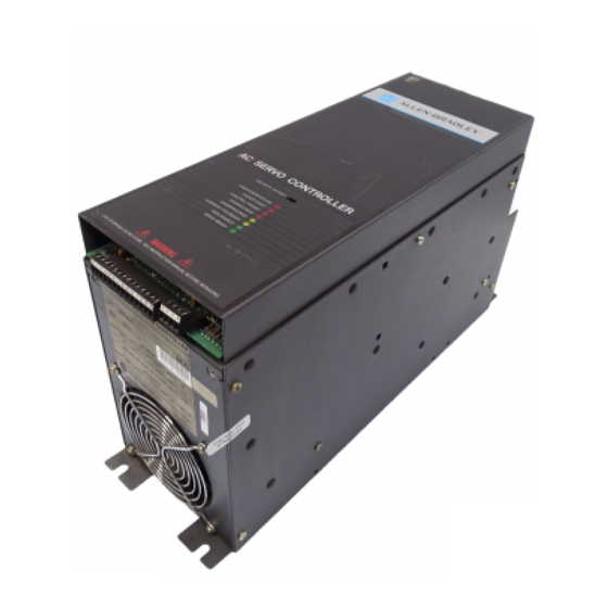
- Page 7 Chapter 1 Introduction Figure 1.1 1391B-ES AC Servo Controller Ground Stud Fuse Circuit Breaker Diagnostic LED’s...
- Page 8 Chapter 1 Introduction End of Chapter...
- Page 9 Chapter Specifications Chapter Objectives Chapter two contains the electrical and environmental specifications for the 1391B-ES. Dimensions are provided in Appendix A. Controller Specifications The general specifications of the 1391B-ES are provided in the listing below. The specifications are divided when necessary for the various controller ratings.
- Page 10 3300 feet (1000 meters) without derating, however, the current rating must be derated by 3% for each additional 1000 feet (305 meters) up to 10,000 feet (3050 meters). Consult with your local Allen-Bradley Sales Representative prior to operation over 10,000 feet (3050 meters). Controller Power Dissipation The 1391B-ES dissipation characteristics are approximated in Table 2.A.
- Page 11 Important: Power Dissipation figures shown are for use in calculating cumulative system heat dissipation to ensure ambient temperature inside enclosure does not exceed 60 C (140 F).
- Page 12 Chapter Receiving, Unpacking and Inspection Chapter Objectives Chapter 3 provides the information needed to unpack, properly inspect and if necessary, store the 1391B-ES and related equipment. The section entitled Inspection provides a complete explanation of the 1391B-ES catalog numbering system. Receiving It is the responsibility of the user to thoroughly inspect the equipment before accepting the shipment from the freight company.
- Page 13 Chapter 3 Receiving, Unpacking and Inspection Isolation Transformer 1391 – First Position Second Posi- Third Posi- Fourth Position Fifth Posi- tion tion tion Bulletin Primary Voltage Secondary Number & Frequency Voltage Type kVA Rating Let- Description Num- Letter Description Letter Description Trans- 240/480V AC,...
- Page 14 Three- Cont./ assigned to special Internal Phase 30A Peak modifications. Extended Heat Sink Contact your local Speed 22.5A RMS Allen-Bradley Sales Range Cont./ Representative for 45A Peak further information. 45A RMS Code Description Cont./ Must be or- 90A Peak dered when...
- Page 15 Chapter 3 Receiving, Unpacking and Inspection 1326AB Servomotor 1326 – – – First Position Second Posi- Third Posi- Fourth Position Fifth Posi- Sixth Position Seventh Posi- Eighth Posi- tion tion tion tion tion Mounting & Bulletin Motor Max. Op. Standard Number Type Design...
- Page 16 Chapter 3 Receiving, Unpacking and Inspection Motor Junction Box Kit 1326A – – First Position Second Posi- Third Posi- tion tion Bulletin Type Description Number Code Description Code Description Modifica- For all AB-A and tion Kit AB-B Series Motors For all AB-B4 and AB-Cx Series Motors The motor comes standard with IP65 plug style connectors mounted radially to the motor.
- Page 17 Chapter 3 Receiving, Unpacking and Inspection Feedback Coupling 1326 – – First Position Second Posi- Third Posi- tion tion Coupling Bulletin Type Size Number – Size Motor Shaft to Encoder Shaft Code Description Code 3/8” to 3/8” (9.5 mm to Modifica- tion Kit 9.5 mm)
- Page 18 Chapter 3 Receiving, Unpacking and Inspection Power and Feedback Cables 1326 – First Position Second Posi- Third Posi- Fourth Position Fifth Position Sixth Position tion tion Bulletin Power Track Motor Size Cable Number Type Function Cable Used On Length Letter Description Letter Description...
- Page 19 Chapter 3 Receiving, Unpacking and Inspection End of Chapter 3-17...
- Page 20 Chapter Description of Operation Chapter Objectives Chapter 4 is intended to familiarize the reader with the circuitry of the 1391B-ES in terms of function and operation. General The 1391B-ES PWM Servo Controller is made up of the following: 300V DC power supply, power transistor output modules, shunt regulator circuit, logic power supply, Logic Control Boards, isolated current sensing, circuit breaker and line contactor.
- Page 21 Chapter 4 Description of Operation The three-phase relationship between the reference signal and the timing wave provide a PWM wave to the power transistor base drive. This base drive switches the power transistors across the 300V DC bus, providing current to the motor windings, thus causing the motor to turn. A resolver attached to the motor provides a signal corresponding to the actual rotor position of the motor.
- Page 22 Chapter 4 Description of Operation The shunt regulator behavior is further modified by an adjustable duty cycle timer. The timer is used to model the shunt resistor temperature. SW1, a selector switch located on the top of the controller (see Figure 1.1) determines the temperature level and therefore the average power level at which the controller will trip out.
- Page 23 Chapter 4 Description of Operation Fault Monitoring and Detection A number of Fault Monitor and Detection functions exist on the 1391B-ES that guard the controller and help to minimize motor and system faults. The occurrence of a fault will cause the controller to trip out. In this condition, the Drive OK (DROK) contact will open and remain open until the fault is cleared.
- Page 24 Important: The 1391B-ES contains a definite purpose contactor that is not to be energized/de-energized more than twice an hour on a continuous basis. The life of the contactor may be reduced considerably if the cycle is exceeded. Contact your local Allen-Bradley Sales Representative for additional information. Power Driver Board The Power Driver Board contains the circuitry needed to switch the power transistor modules.
- Page 25 Chapter 4 Description of Operation ATTENTION: The user has the ultimate responsibility to determine which stopping method is best suited to the applica- tion and will meet applicable standards for operator safety. Starting and Stopping must be accomplished by hardwired user supplied elements as shown in Appendix B.
- Page 26 Chapter 4 Description of Operation Power-Up/Down Sequence Figure 4.4 describes the various steps involved in the power-up/down sequence of the 1391B-ES controller. Figure 4.4 Controller Power-Up / Down Sequence POWER-UP POWER-DOWN SEQUENCE SEQUENCE Application of 240V AC to Isolation Enable Signal Removed Transformer Fault a) Motor will regenerate to a stop.
- Page 27 Chapter 4 Description of Operation End of Chapter 4-25...
- Page 28 Chapter Inputs, Outputs and Adjustments Chapter Objectives Chapter 5 contains descriptions of the various inputs and outputs available on the 1391B-ES Servo Controller. Additionally, a comprehensive listing and description of the potentiometer and switch adjustments is provided. In some cases adjustment methods are provided for use during start-up. This information is provided to help you understand some of the important aspects about the controller prior to the actual installation and start-up.
- Page 29 Chapter 5 Inputs, Outputs and Adjustments Adjustable Current Limit (TB2, Terminal 5) The current limit of the controller is set to 300% or twice the continuous rating of the controller, whichever is lower. Connecting this terminal to Signal Common will enable potentiometer R148. The range of this pot is 20 to 300% or twice the continuous rating of the controller, whichever is lower.
- Page 30 When interfacing to IMC 121 or 123 controllers, use the 1391-CAQB cable. The A Quad B option operates in the same manner as the Allen-Bradley 845H Line Driver Encoder (26LS31 line driver output). The option requires either a regulated +5V DC at terminal 7 or an unregulated +8 to +15V DC input at terminal 9 (board draws 125mA maximum).
- Page 31 DC Bus. To use an external shunt resistor, first remove the jumper at terminals 8 and 10 of TB5. Consult the Allen-Bradley sales office for application assistance. The shunt regulator resistor supplied with the 1391B-ESAA45 must be externally mounted and connected to terminals 8 and 9 of TB5 prior to operation.
- Page 32 Chapter 5 Inputs, Outputs and Adjustments Figure 5.2 Terminal Block, Potentiometer and Switch Locations Resolver Signals Current Feedback Scaling Switch Configuration Switch Adjustable Current Limit R148 Offset Overtemperature (red) Power Factor (red) Control Power (red) Gain Overvoltage (red) Undervoltage (yellow) Scale R132 R144...
- Page 33 Chapter 5 Inputs, Outputs and Adjustments Potentiometer Adjustments Preliminary adjustment of the Logic Control Board potentiometers is required as explained below. Descriptions of the potentiometers follow. Initially the potentiometers shall be set as shown in Table 5.A. See Figure 5.2 for potentiometer locations. Table 5.A Initial Potentiometer Settings Potentiometer...
- Page 34 Chapter 5 Inputs, Outputs and Adjustments Switch Settings This section provides information on setting the Duty Cycle Selector switch (SW1), Current Scaling switch (S1), configuration switches (S2) and the A Quad B Encoder Output switch (S3). Refer to Figure 5.2 for switch locations.
- Page 35 Chapter 5 Inputs, Outputs and Adjustments Table 5.B Typical Current Feedback Scaling Motor Rated Current 1391B-ESAA1 1391B-ESAA2 1391B-ESAA4 S1 Switch Setting 15.0 22.5 45.0 14.1 21.1 42.2 13.1 19.7 39.4 12.2 18.3 36.6 11.3 16.9 33.8 10.3 15.5 30.9 14.0 28.1 12.6 25.3...
- Page 36 Chapter 5 Inputs, Outputs and Adjustments Configuration Switch - S2 Prior to start-up, the switch positions of S2 must be checked against the listing in Table 5.D to ensure proper setting. Refer to the paragraphs following the table for switch descriptions. ATTENTION: Only personnel familiar with the 1391B-ES controller and its associated machinery should plan or implement the adjustment, calibration, start-up and subsequent...
- Page 37 The ID point differs with the motor used. Refer to Table 5.E for switch settings. For motors not listed, consult your Allen-Bradley Sales Representative. Table 5.E S2-2 Switch Positions...
- Page 38 Chapter 5 Inputs, Outputs and Adjustments Torque Block/Velocity Loop Operation (S2-5) Switch S2-5 is used to disable the velocity error amplifier to configure the controller for torque block operation. In torque block mode the controller acts as a current amplifier producing current (torque) proportional to the command present at terminals 15 and 16 of TB2.
- Page 39 (similar to Allen-Bradley 845H) Z (NOT) When using the A Quad B option with Allen-Bradley IMC motion controllers, the AMP parameters will be set according to the line count selected. In general, one parameter must be justified when using this device.
- Page 40 The National Electrical Code and any other governing regional or local code will overrule this information. The Allen-Bradley Company cannot assume responsibility for the compliance or the noncompliance to any code, national, local or otherwise for the proper installation of this controller or associated equipment.
- Page 41 Consult the National Electrical Code for factors on ambient conditions, length etc. or the Allen-Bradley Sales Representative in your area for further information. Shielding Reasonable care must be taken when connecting and routing power and signal wiring on a machine or system.
- Page 42 The 1391B-ES system is designed to be interconnected with Allen-Bradley EMI shielded motor cables only. Do Not substitute cables. The EMI shield of the motor cable only, must be grounded at both ends to function properly.
- Page 43 TB5, but codes must be followed. In addition, the motor leads must be twisted throughout their entire length to minimize radiated electrical noise. Allen-Bradley 1326 cables must be used. The maximum motor wire sizes that the 1391B-ES controller will accept are shown in Table 6.A.
- Page 44 Installation Motor Feedback Wiring Connections to the integral commutation resolver must be made using an Allen-Bradley 1326-CFUxx shielded cable. ATTENTION: To guard against hazard of personal injury or damage to equipment, the interconnections to the motor and resolver must be made exactly as shown in Appendix B. Failure to do so could cause loss of motor control and/or severe oscillation of the motor shaft.
- Page 45 Chapter 6 Installation Fusing (Transformer Primary) Time delay fusing similar to Bussman Fusetron FRS Series or equivalent must be used if the primary circuit is fused. Circuit breakers must provide equivalent operation. Fuse ratings shown in Table 6.C are the highest ratings allowed in a 25 C (77 F) ambient temperature.
- Page 46 Chapter Start-Up Chapter Objectives Chapter 7 provides the steps needed to properly start-up the 1391B-ES AC Servo Controller. Included in the procedure are typical adjustments and voltage checks to assure proper operation. Start-Up Procedure The following procedure provides the required steps to start-up the 1391B-ES AC Servo Controller in velocity and position mode.
- Page 47 Chapter 7 Start-Up 3. Assure that preliminary adjustment of the following items has been performed: - Potentiometer adjustments as described in Chapter 5. - S1, S2 and SW1 switch settings as described in Chapter 5. Important: The above adjustments must be performed before proceeding.
- Page 48 Chapter 7 Start-Up 9. The wires connected to terminals 1 & 2 of TB2 (Velocity Command Input) must be marked and removed. A 10V DC local control (battery box) is to be connected to these terminals. See Figure 7.1. The polarity of the Command signal from the battery box should be the same as the actual control source to assure correct motor rotation when the controller is placed into operation as part of the system.
- Page 49 Chapter 7 Start-Up 11. If adjustable current limit is not desired, proceed to step 12. Ground TB2-5 to TB2-6. Set Current Limit to zero. With a 10% Command input signal applied to terminals 1 and 2 of TB2, momentarily close the local Enable switch and observe motor speed and direction of rotation.
- Page 50 Chapter 7 Start-Up Figure 7.2 Velocity Response Profiles R144 Controls Amount of Overshoot Commanded Velocity Underdamped Critically Damped Overdamped Time System Compensation Procedure 18. Monitor the velocity feedback signal at terminals 6 (common) and 7 of TB2 with an oscilloscope or chart recorder. ATTENTION: If an oscilloscope (or chart recorder) is used during Start-Up or Troubleshooting, it must be properly grounded.
- Page 51 Chapter 7 Start-Up 20. Remove power with the branch circuit disconnect. 21. Remove the local Enable switch and reconnect external wiring. 22. Apply power and check system operation. 23. Remove power with the branch circuit disconnect and if necessary, reconnect motor to load. 7-49...
- Page 52 Chapter 8 describes the operation of a standard 1326 AC Servomotor with the enhanced capabilities of a Bulletin 1391B-ES AC Servo Controller. Refer to the 1326 AC Servomotor Product Data for further information on Allen-Bradley AC Servomotors. Introduction The 1391B-ES provides additional energy to the 1326 motor, allowing it to operate at higher speeds without a reduction of torque.
- Page 53 Chapter 8 The 1326 AC Servomotor Tp – the peak torque that can be produced by the motor/controller combination with both at rated temperature and the motor in a 40 C ambient and the controller in a 60 C ambient. Since 200% current torque peaks are common in many applications for optimal controller usage, the following curves show typical system performance.
- Page 54 46.6 989/111.8 1326AB-C4B 0.29/0.032 All ratings are for 40 C motor ambient,110 C case and 60 C amplifier ambient. For extended ratings at lower ambients contact Allen-Bradley. 420/47.4 1391B-AA45 38.2 The motor contains two thermal switches wired in series that will open on an overtemperature condition. They are set to open at 150 C (typical) and close at 90-100 C (typical).
- Page 55 Chapter 8 The 1326 AC Servomotor End of Chapter 8-57...
- Page 56 Logic Control Board. It is recommended that a 1391 Isolation Transformer be used. Contact your local Allen-Bradley Sales Representative if a transformer of a different type must be used. Refer to Figure 9.1 and Appendix B for connection information.
- Page 57 Important: The NEMA Type 1 enclosure is shipped as a kit for customer assembly. If other input voltages or special enclosures are required, consult your local Allen-Bradley Sales Representative. Refer to Figure 9.1 for connection information and Appendix A for dimensions. 9-55...
- Page 58 Chapter 9 Transformers and Shunt Regulators Figure 9.1 1391 Transformer Wiring Diagrams 1391-TxxxDT Primary Voltage Connect Lines On 240V AC H1 to H3 to H8 H2 to H4 to H6 H5 to H7 to H9 480V AC H2 to H3 H5 to H6 H8 to H9 H3 H2...
- Page 59 Chapter 9 Transformers and Shunt Regulators Shunt Regulator Operation Refer to Chapter 4 for an explanation of the shunt regulator circuitry. The nominal data for the shunt regulator is as follows:. Overvoltage Trip Point = 405V DC 2.5% DC Bus Shunt “ON” Point = 386.4V DC DC Bus Shunt “OFF”...
- Page 60 Chapter 9 Transformers and Shunt Regulators Table 9.B shows the nominal resistor power trip levels in watts for the various switch settings. When shunt requirements exceed the selector setting, the excess power will cause the bus voltage to rise, resulting in an overvoltage fault condition.
- Page 61 (deceleration) may be an indication that an external shunt resistor having increased power dissipation capacity is required. Based on the data supplied, Allen-Bradley will specify a shunt resistor with the proper resistance value for the controller being used.
- Page 62 Chapter 9 Transformers and Shunt Regulators ATTENTION: Proper derating must be applied to the manufacturers nominal resistor power ratings when using these in external shunt configurations. Consult the resistor manufacturer for recommended derating. Failure to comply could result in personal injury and/or equipment damage from an overheated resistor.
- Page 63 Chapter 9 Transformers and Shunt Regulators End of Chapter 9-61...
- Page 64 Chapter Troubleshooting Chapter Objectives Chapter 10 provides information to guide the user in troubleshooting the 1391B-ES. Included in the chapter are LED descriptions and fault diagnosis, general system troubleshooting and test point descriptions. System Troubleshooting Most controller faults are annunciated by the LED diagnostic indicators on the front of the controller.
- Page 65 Chapter 10 Troubleshooting Table 10.A LED Descriptions and Fault Diagnosis LED Description Potential Cause OVERTEMPERATURE The controller contains a thermal OVERTEMPERATURE LED is Illuminated (RED) switch on the heat sink which The logic supply ( 12V DC, +5V DC) circuits have malfunctioned senses the power transistor (fuse blown etc.) or the AC input at TB4-19, 20, 21 is incorrectly wired.
- Page 66 Chapter 10 Troubleshooting Table 10.A LED Descriptions and Fault Diagnosis (Continued) LED Description Potential Cause UNDERVOLTAGE The logic supplies have dropped 10% below their nominal value (Continued) 1. The input line voltage is out of tolerance. 2. The transformer auxiliary logic supply winding is open. 3.
- Page 67 Chapter 10 Troubleshooting Table 10.B General System Troubleshooting Condition Possible Cause Axis or System runs uncontrollably 1. The velocity feedback, position feedback device or velocity command signal wiring is incorrect or open. 2. An internal controller malfunction exists. 1. Velocity Loop Compensation or Gain potentiometer is incorrectly set. Axis or System is unstable 2.
- Page 68 Chapter 10 Troubleshooting Table 10.C General Servomotor Troubleshooting Condition Possible Cause No Rotation 1. The motor connections are loose or open. 2. Foreign matter is lodged in the motor. 3. The motor load is excessive. 4. The bearings are worn. Overheating 1.
- Page 69 Chapter 10 Troubleshooting Figure 10.1 Logic Control Board Test Point Locations Resolver Signals TP11 Current Feedback Scaling Switch Configuration Switch Adjustable Current Limit R148 TP13 TP21 TP12 TP14 Offset Overtemperature (red) Power Factor (red) Gain Control Power (red) Overvoltage (red) Undervoltage (yellow) Scale R132...
- Page 70 Chapter 10 Troubleshooting Figure 10.2 1391B–ES Top Panel Ground Stud F3 provided on 15 and 22.5A units only. 15A = KLM-10 1 / 4 22.5 = FNQ 6 series B only 10-68...
- Page 71 Chapter 10 Troubleshooting End of Chapter 10-69...
- Page 72 Appendix Dimensions Figure A.1 1391B-ES Dimensions Dimensions are in inches and (millimeters) Detail A 0.25 (6.3) 0.312 (7.9) Dia. 6.00 (152.4) 0.60 (15.2) Dia. 5.20 (132.1) 0.30 (7.6) 3.70 (93.9) See Detail A 19.00 (482.6) 18.40 (467.4) 17.50 (444.5) AC SERVO CONTROLLER OVERTEMPERATURE POWER FACTOR CONTROL POWER...
- Page 73 X0 & X3 SECONDARY VOLTAGE NOM. X0 & X2 INSULATION CLASS 0.53 X0 & X1 NO. OF PHASES VENDOR PART NO. (13.5) ALLEN-BRADLEY 0.44 (11.2) Ref. A Max. C Max. Catalog Number Weight 1391-T015DT 9.00 (228) 10.00 (254) 13.00 (330) 5.00 (127)
- Page 74 Appendix A Dimensions Figure A.3 NEMA Type 1 Enclosure Dimensions Dimensions are in inches and (millimeters) Front Side Catalog Number Weight 1391-TA2 17.00 (432) 19.00 (483) 14.50 (368) 16.50 12.00 35.5 (16.1) (419) (305) A-72...
- Page 75 Appendix A Dimensions Figure A.4 External Shunt Resistor and Fuse Dimensions Dimensions are in inches and (millimeters) 5.38 (136.6) 12.75 (323.8) 14.00 (355.6) 2.25 1.13 (57.1) (28.7) 1.87 (47.5) 0.281 x 0.562 (7.1 x 14.2) 0.203 (5.2) Dia. w/ 0.343 (8.7) Dia. C.B. 2.81 (71.4) 0.91...
- Page 76 Interconnect Drawings Objectives Appendix B provides typical interconnection diagrams that illustrate the wiring between the 1391B-ES and various other Allen-Bradley position control products. Due to the numerous electrical circuit designs possible, these diagrams are provided for reference only. The diagrams provided include: - 1391B-ES interconnect drawing showing the inputs, outputs and recommended control circuitry.
- Page 77 Appendix Cable Information Cable Wiring Information Pin-outs and interconnect information for the various 1326 cables are provided in this section. 1326-CFUxx Commutation Cable Servo Control Connection Gauge Connector 1389-AAxx 1391-AAxx Wire Color (AWG) Terminal # Terminal # Black TB2-1 TB1-10 White TB2-2 TB1-9...
- Page 78 Appendix C Cable Information 1326-CPCxx Motor Power Cable Servo Control Connection Wire Wire Gauge Connector 1389-AAxx 1391-AAxx Number Color (AWG) Terminal # Terminal # Black TB3-1 TB5-1 Black TB3-2 TB5-2 Black TB3-3 TB5-3 Drain Wire Power Ground Power Ground Black Power Ground Power Ground Black...
- Page 79 Appendix C Cable Information 1391-CAQB A Quad B Cable The 1391-CAQB cable allows the user to connect directly from an IMC 121, 123, 123CR or 9/240 controller to the 1391B-ES controller (with A Quad B Board installed). The 1391-CAQB Cable also carries the controller command voltage, which is connected to TB2-1 and TB2-2.
- Page 80 Appendix C Cable Information End of Appendix C-78...
- Page 81 Appendix Controller Options Zero Current Option (-A13) The Zero Current Option allows the user to externally adjust the current limit of the controller from zero to 200% of the rated controller output. Operation/Set-up ATTENTION: To avoid a shock hazard, assure that all power to the controller has been removed before connecting potentiometer.
- Page 82 Appendix D Controller Options End of Appendix D-80...