Table of Contents
Quick Links
Table of Contents
Troubleshooting

Related Manuals for Dormakaba RAC5 MFC


Summary of Contents for Dormakaba RAC5 MFC
- Page 1 RAC5 MFC Installation Guide...
-
Page 2: Table Of Contents
7 Annex C: Electromagnetic Interference ..........18 8 Annex D: RAC5 MFC Components ............19 9 Annex E: Single Reader Wiring ............. 20 10 Annex F: Dual Reader Wiring .............. 20 12-2020 dormakaba Canada Inc. RAC5 MFC Installation Guide – PK3738 | 1... - Page 3 11 Annex G: Fire Alarm Panel Wiring ............21 12 Annex H: Reader Drilling Template ............ 22 12-2020 dormakaba Canada Inc. RAC5 MFC Installation Guide – PK3738 | 2...
-
Page 4: Introduction And Disclaimers
Do not connect to a receptacle controlled by a switch. If installing the RAC5 MFC in an elevator cage environment, or in proximity to any other equipment that may generate high levels of electromagnetic interference, follow the installation requirements as indicated in Annex C to prevent any operational instability. -
Page 5: Safety Procedures
This device complies with Part 15 of the FCC Rules. Operation is subject to the following two conditions: (1) This device may not cause harmful interference, and (2) This device must accept any interference received, including interference that may cause undesired operation. 12-2020 dormakaba Canada Inc. RAC5 MFC Installation Guide – PK3738 | 4... -
Page 6: Product Description
For surface mount, the surface area required for the contactless reader is 5"W x 5"H x 2"D (12.7 x 12.7 x 5cm, 2" depth behind panel required). The RAC5 MFC is an access control solution that can operate 2 individual card readers, provides multiple relays, and much more as per the feature list below. -
Page 7: Components
Power Supply: Provides the DC power required for operation of the controller PCB and all peripherals Controller Board: Controls all the features of the RAC5 MFC system Tamper Switch: Attached to the RAC5 MFC enclosure to generate an alarm if the box is opened during operation Power &... -
Page 8: Contactless Card Reader
3.1.3 Cables (not shown) NOTE: All items come factory installed. System cables: Power supply to LEDs, controller PCB and controller PCB jumpers 3.1.4 Card Reader(s) Contactless reader (see Figure 3) 12-2020 dormakaba Canada Inc. RAC5 MFC Installation Guide – PK3738 | 7... -
Page 9: Power Adapter
Slotted screwdriver – 3/32” tip width • Adjustable wrenches • Crimp tool – 18-22 AWG • Pliers • Wire cutter/stripper • Hammer or rubber mallet • Awl or centre punch 12-2020 dormakaba Canada Inc. RAC5 MFC Installation Guide – PK3738 | 8... -
Page 10: Exploded View
Ensure all components ordered and materials/tools required are available • Ensure all cabling is available for the peripherals/components being installed All installations and wiring of RAC5 MFC enclosure & peripherals must comply with all IMPORTANT applicable local building codes and regulations and National Electric Code, ANSI/NFPA 70. -
Page 11: Pre-Installation Procedures
Access to the RAC5 MFC enclosure must be restricted to authorized personnel • AC power must be available within 6 feet (1.8 m) of the RAC5 MFC enclosure • The location temperature must be from 0 to 49 °C (32 to 120 °F) and sheltered against weather hazards and dripping water with relative humidity conditions less than 85% at 32 °C (90 °F) - Page 12 To wire the tamper switch to the premise alarm system, disconnect the wires on controller PCB connected J7 pins 1 & 2 and run a 2-connector cable from the switch to the premise alarm system 12-2020 dormakaba Canada Inc. RAC5 MFC Installation Guide – PK3738 | 11...
- Page 13 Several floors can be controlled by one relay (one common area). The relays in the RAC5 MFC are UL rated and are capable of a maximum switching of 30 VDC @ 1A. For time duration of relay state change, please refer to Annex B, Figure 8.
- Page 14 (recommended with tie wraps) iii. Crimp the fork terminals supplied in the hardware bag to the end of the wires and connect them to the power adapter screw terminals 12-2020 dormakaba Canada Inc. RAC5 MFC Installation Guide – PK3738 | 13...
- Page 15 7. Complete the installation. a) If the access door was removed, reinstall the door to the RAC5 MFC enclosure b) Bend the two tabs on the door to a maximum of 30 degrees as shown in Figure 7 Figure 7 – Door Tabs...
-
Page 16: Annex A: Quick Troubleshooting Guide
Annex B, Figure 8 5.2 Card Reading Troubleshooting Symptom Action Verify that the RAC5 MFC controller is active. If not, restart the RAC5 • MFC controller: Press the Reset Switch (SW1) or disconnect and No feedback on Reader when reconnect the power using a card •... -
Page 17: External Inputs Troubleshooting
Tamper Switch 5.4 Relay Expansion Board Troubleshooting The power for the RAC5 MFC must be turned off before connecting or disconnecting the CAUTION Relay Expansion Board. LEDs on Relay Expansion board are normally OFF, meaning no trouble. -
Page 18: Annex B: Multi-Floor Controller Rac5 Mfc
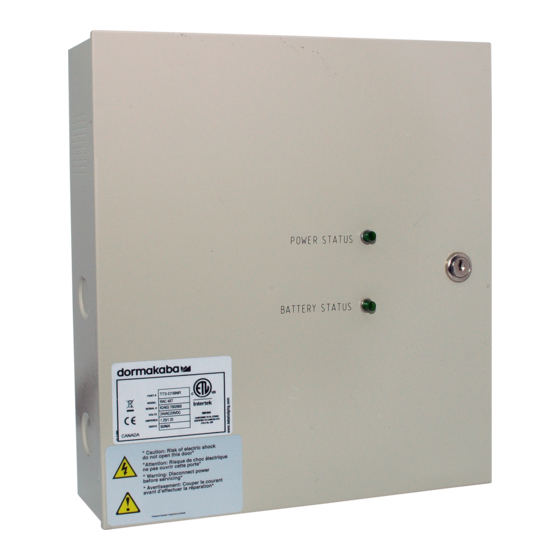
- GREEN LEDs are "OFF" & Controller Board can activate Low Bat-1 Yellow ( - ) relays. Battery Status DC Out-2 ( + ) ( + ) Red* ( + ) 12-2020 dormakaba Canada Inc. RAC5 MFC Installation Guide – PK3738 | 17... -
Page 19: Annex C: Electromagnetic Interference
7 Annex C: Electromagnetic Interference As per any other electronic equipment, the RAC5 MFC can be affected by electromagnetic interference cause by industrial electrical equipment such as elevator motors. To prevent the unit from operational instability, such as ‘freezing’ or losing programming, shielded cables should be used and connections made as per the diagram below. -
Page 20: Annex D: Rac5 Mfc Components
8 Annex D: RAC5 MFC Components Figure 10 – RAC5 MFC Components 12-2020 dormakaba Canada Inc. RAC5 MFC Installation Guide – PK3738 | 19... -
Page 21: Annex E: Single Reader Wiring
READE R 2 READE R 1 1 (+) 2 (-) 3 (+) 4 (-) RD#1 RD#2 Green Black White RAC5 NFC Wall Reader Maximum cable length of 1000 Feet 12-2020 dormakaba Canada Inc. RAC5 MFC Installation Guide – PK3738 | 20... - Page 22 Normally Closed dry contact output. Note 2: If the Fire Alarm Panel connection is not required, place a jumper wire between pin 3 and 4 of J18. 12-2020 dormakaba Canada Inc. RAC5 MFC Installation Guide – PK3738 | 21...
- Page 23 12 Annex H: Reader Drilling Template Figure 15 – Reader Drilling Template (not to scale) 12-2020 dormakaba Canada Inc. RAC5 MFC Installation Guide – PK3738 | 22...
- Page 24 Canada Inc. www.dormakaba.us...