Emerson TARTARINI FL Series Instruction Manual
Pilot-operated pressure regulator
Hide thumbs
Also See for TARTARINI FL Series:
- Installation manual (10 pages) ,
- Instruction manual (36 pages) ,
- Instruction manual (25 pages)
Table of Contents
Instruction Manual
0014EN-FL-IM
November 2008 - Rev. 01
FL Series Pilot-Operated Pressure Regulator
SummaRy
Introduction ........................................................................ 1
P.E.D. Categories and Fluid Group ................................... 2
Characteristics ................................................................... 2
Labelling ............................................................................ 3
Overpressure Protection .................................................... 3
Transport and Handling ..................................................... 3
Atex Requirements ............................................................. 4
Description ......................................................................... 4
Pilots .................................................................................. 5
Dimensions and Weights ................................................... 6
Operation ........................................................................... 8
Installation ......................................................................... 9
Startup ............................................................................... 11
Pilot Adjustment ................................................................. 12
Shutdown ........................................................................... 12
Periodical Checks .............................................................. 12
Regulator Maintenance ..................................................... 12
Type OS/80X Actuator Maintenance ................................. 15
Type PS/ and PRX/ Pilot Maintenance .............................. 16
Type V/31-1 Booster Valve Maintenance .......................... 20
Type SA/2 Stabilizer Filter Maintenance ............................ 20
Spare Parts ........................................................................ 20
Troubleshooting ................................................................. 21
Parts List ............................................................................ 23
Schematic Assemblies........................................................ 28
INTRODuCTION
Scope of manual
This manual provides instructions for installation, startup,
maintenance and spare parts ordering for the FL Series
pilot operated regulators. It also contains information for the
actuator, pilots, booster valves and filter.
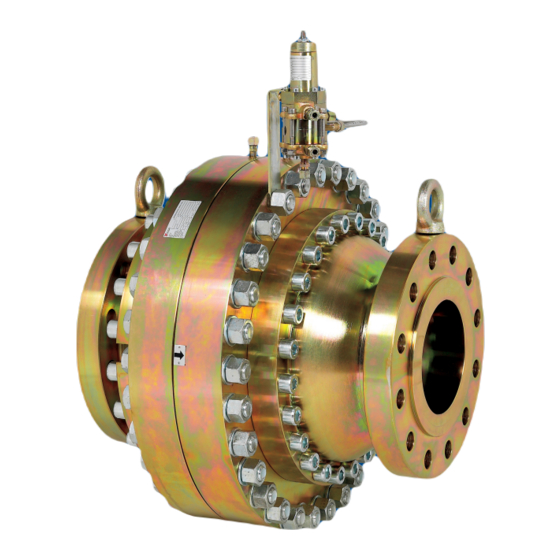
Figure 1. Regulator Type FL with PRX Pilot
Product Description
The FL Series pilot operated regulators are axial flow type
with a single seat and counterbalanced shutter.
The following versions are available:
FL:
Regulator
mFL: Regulator - Monitor
BFL: Regulator - Slam-shut Device
Type SR, SRII and/or SRS silencers are also available.
All standard gas pressure devices (regulators and safety
shut-off devices) used in assemblies will comply to EN
12186 and EN 12279 standards.
Any accessories (e.g. pilots or filters) used on the Emerson
Process Management range of pressure regulators,
with or without built-in safety shut-off devices, must be
manufactured by one of the Emerson Process Management
companies and bear that label.
If this is not respected, Emerson Process Management will
not be responsible in the case of any inefficiency.
In a configuration with integrated safety shut-off device and
pilot, when the maximum allowable pressures are different,
the slam-shut device is the differential strength type.
Type FL
Table of Contents

Related Manuals for Emerson TARTARINI FL Series


Summary of Contents for Emerson TARTARINI FL Series
-
Page 1: Table Of Contents
EN 12186 and EN 12279 standards. Parts List ................23 Any accessories (e.g. pilots or filters) used on the Emerson Schematic Assemblies............28 Process Management range of pressure regulators, with or without built-in safety shut-off devices, must be... -
Page 2: Categories And Fluid Group
Type FL PED CaTEGORIES aND FLuID GROuP FL-BP • MFL-BP with Type SRS silencer or widened outlet DN 25x100 - 40x150 - 50x150 - 65x200 - 80x250 - 100x250 - 150x300 The FL series regulators without built-in safety slam-shut PN 16-25-40 UNI/ DIN devices (FL and MFL) may be used as a stand-alone safety ANSI 150 flanged accessory in a fail-to-close configuration to protect pressure... -
Page 3: Labelling
Type FL OvERPRESSuRE PROTECTION Minimum/Maximum Allowable Temperature (TS) See Nameplate The recommended safety pressure limitations are stamped on the regulator nameplate. If actual version hasn’t a built-in safety 1. The pressure/temperature limits indicated in this instruction manual or any shut-off device, some type of overpressure protection is needed applicable standard or code limitation should not be exceeded. -
Page 4: Atex Requirements
Type FL aTEX REquIREmENTS If the provisions of EN 12186 and EN 12279, • with a view to preventing and providing protection against national regulations, if any, and specific manufacturer explosions, technical and/or organisational measures recommendations are not put into practice before appropriate to the nature of the operation shall be taken installation and if purge by inert gas is not carried out before (e.g. -
Page 5: Pilots
Type FL PILOTS The FL Series regulators are equipped with the PS/ or PRX/ series pilots and with OS/80X or OS/80X-PN series slam shut device. Table 3. Pilot Type PS/ and PRX/ Characteristics application Allowable Pressure Set Range Body and Covers Operating monitor Regulator or PS (bar) -
Page 6: Dimensions And Weights
Type FL DImENSIONS aND WEIGhTS STaNDaRD aND TyPE SR vERSIONS WIDENED OuTLET aND TyPE SRS vERSIONS FL-BP FL-BP mFL-BP mFL-BP BFL-BP BFL-BP Figure 4. Type FL-BP Series Dimensions Table 8. Type FL-BP Series Dimensions FaCE TO FaCE - I (mm) DImENSIONS (mm) FaCE TO FaCE - I (mm) DImENSIONS (mm) - Page 7 Type FL DImENSIONS aND WEIGhTS STANDARD AND TyPE SR/SRII VERSIONS WIDENED OUTLET AND TyPE SRS/SRSII VERSIONS Figure 5. Type FL Series Dimensions Table 10. Type FL Series Dimensions FaCE TO FaCE - I (mm) DImENSIONS (mm) FaCE TO FaCE - I (mm) DImENSIONS (mm) ANSI 300 - ANSI 600 ANSI 300 - ANSI 600...
-
Page 8: Operation
Type FL OPERaTION INLET PRESSURE, Pu PILOT PILOT REGULATOR MOTORIZATION PS/80 PS/79 PRESSURE, Pm MONITOR MOTORIZATION PRESSURE, Pm STABILIZED PRESSURE, Pup OUTLET PRESSURE, Pd DOWNSTREAM OR IN A SAFE AREA, Pb BFL/ SLAM-SHUT MONITOR REGULATOR Figure 6. Types BFL and FL Operational Schematic Regulator The purpose of this device is to protect the system against possible overpressure, while keeping the reduction line in service. -
Page 9: Installation
Type FL INSTaLLaTION PS/79-1 PS/79-2 4 x DN 6 x DN TyPE FL-BP REGULATOR WITH PILOT PS/79-1-2 PS/79 To the heating 4 x DN 6 x DN TyPE FL REGULATOR WITH PILOT PS/79 PRX/120 PRX/120-AP SA/2 To the heating 4 x DN 6 x DN TyPE FL REGULATOR WITH PILOT PRX/120 OR PRX/120-AP LEGEND:... - Page 10 Type FL PS/80 PS/79 4 x DN Monitor Regulator 6 x DN TyPE FL REGULATOR AND MONITOR WITH PILOT PS/79 AND PS/80 PRX/120-AP PRX/120-AP PRX/120 PRX/120 PRX/131 SA/2 4 x DN Monitor Regulator 6 x DN TyPE FL REGULATOR AND MONITOR WITH PILOT PRX/120 AND BOOSTER VALVE PRX/131 REO/80 PSO/80 PRX/131...
-
Page 11: Startup
Type FL INSTaLLaTION (continued) According to EN 12186 and 12279, where this product is used: • Provide a cathodic protection and electrical • Ensure that the data found on the regulator plate are isolation to avoid any corrosion; compatible with usage requirements. •... -
Page 12: Pilot Adjustment
Type FL REGuLaTOR maINTENaNCE a. Let the filtered, and if necessary preheated, gas reach the regulator. (SEE FIGURES 8 TO 18) b. Slightly open the On-Off valve located downstream. c. Open the On-Off valve located upstream just slightly and WaRNING very slowly. - Page 13 Type FL FL and mFL Regulator General maintenance As you proceed, make sure that parts move freely and without friction. a. Disconnect all fittings, remove regulator from the line and In addition: place it in upward vertical position. a. Before fitting sleeve-diaphragm assembly (keys 16 and b.
- Page 14 Type FL To prevent this, replace the two screws In addition: (key 9) with threaded rods and their nuts, a. Before fitting sleeve-diaphragm assembly (keys 16 and remove the remaining screws and use nuts 10), recompose indicator group (keys 34, 35, 36, 37, to slowly release spring tension.
-
Page 15: Type Os/80X Actuator Maintenance
Type FL ACTUATOR MAINTENANCE OS/80X b. Press the “EMERGENCy” button. This will cause the immediate closing of slam-shut device. SERIES (SEE FIGURE 19) c. Loosen a connector in the downstream line of the slam- Installation shut device or of the regulator. Check the connector with soap and water, making sure there are no leaks;... -
Page 16: Type Ps/ And Prx/ Pilot Maintenance
Type FL g. Remove cover (key 61) on OS/80X Series, or body (key 60) e. Reset pilot and reduce the pressure until it reaches on Types OS/84X and OS/88X, and proceed as directed in minimum cutoff level. replacing diaphragm/O-ring section. f. - Page 17 Type FL In order to better assess the effects of d. Loosen screws (key 10), remove the upper cover adjustments, it is advisable to turn the adjusting (key 8) and the lower cover (key 21). Replace the screws only one fourth of a turn at a time and O-ring (key 18).
- Page 18 Type FL a. Supply fitting A with normal operating pressure. b. Unscrew seat (key 54) and replace pad holder (key 56). b. Make sure there is no gas outflow from fitting B. c. Reassemble by reversing the above sequence, make sure not to “pinch”...
- Page 19 Type FL maintenance CauTION CauTION The above clearance can be checked by gently pulling stem (key 13) upward. Servicing should be carried out by Use the proper tool to make sure that the qualified, skilled personnel only. For top plate (key 9) is on the same plane as the further information, please contact our supporting the diaphragm (key 10) in the body Technical Support Representatives or our...
-
Page 20: Type V/31-1 Booster Valve Maintenance
Type FL Reassembly b. When remounting, make sure that the tightening of the ring nut (key 25) does not put undue stress on diaphragm Lubricate the static O-rings with a thin layer of Molykote (key 23). 55 M, be very careful not to damage the O-rings when c. -
Page 21: Troubleshooting
Type FL TROuBLEShOOTING Table 12. General Troubleshooting for FL Series Regulator SymPTOmS CauSE aCTIONS Lack of incoming gas Check the station feeding Pilot is not being supplied Check pilot connections The regulator does not open Regulator diaphragm is broken To be replaced The slam-shut device has not been reset Manually reset the slam-shut device Insufficient upstream pressure... - Page 22 Type FL Table 14. Troubleshooting for Type PS/79, RE/79, PS/80, and RE/80 Pilots SymPTOmS CauSE aCTIONS Check the springs catalogue and replace it with a Calibration spring (key 5) is too weak stronger one Desired setpoint is not reached Check pilot feed connections and proper gas flow Leaks from pilot connections feeding Filter (key 61) is clogged preventing proper...
-
Page 23: Parts List
Type FL PaRTS LIST Item Description Support FL and mFL Regulator Elastic pin (See Figure 8 to 17) Disk Auto-locking nut Item Description Plate Plate Inlet flange Stud bolt Anti-friction ring Pipe O-ring Spring O-ring Screw Screw Plate Spring O-ring Fitting Spacer Inlet plate... - Page 24 Type FL BFL Regulator with Slam-shut Item Description Washer (See Figure 18) Plate fulcrum Item Description Lever Screw Inlet flange Cone 107* O-ring Releasing lever Disk Spring Washer Plug Locking pin Stud bolt Screw Spring Indicator pin 115* O-ring On-Off indicator Sleeve Button Anti-friction ring...
- Page 25 Type FL Type PRX/120, PRX/125, Item Description PRX-AP/120 and O-ring PRX-AP/125 Pilots O-ring (See Figure 20) (continued) Plate Screw Item Description Plug Plug Filter Plate Diaphragm Type PS/79, RE/79, PS/80 Plate Body and RE/80 Pilots O-ring (See Figure 23) O-ring Seat Item Description...
- Page 26 Type FL Type PS/79, RE/79, PS/80 Type PS/79-1, PS/79-2, RE/79-1 and RE/79-2 Pilots and RE/80 Pilots (See Figure 24) (See Figure 23) (continued) Item Description Item Description Adjusting screw Washer Plate Diaphragm Spring holder Screw unit Spring Seat Cover O-ring Pad holder unit Plate Spring...
- Page 27 Type FL T ype RE/79-1 and RE/79-2 only Item Description Plate Item Description Seat Safety Valve O-ring Body O-ring Seat Washer Thrust bearing “GACO” Ring Filter cover Felt O-ring Type PS/79-1-D, PS/79-2-D, RE/79-1-D and Spring Pad holder unit RE/79-2-D Pilots Data plate Screw plate unit Item...
-
Page 28: Schematic Assemblies
Type FL SChEmaTIC aSSEmBLIES LM/1403 Figure 8. FL Regulator DN 25 to DN 150... - Page 29 Type FL NOT SILENCED FL/ AND BFL/ PAD HOLDER PAD HOLDER DN 25 TO DN 50 DN 65 TO DN 150 FL/ AND BFL/ WITH SR SILENCER PAD HOLDER PAD HOLDER DN 25 TO DN 50 DN 65 TO DN 150 LM/1403 Figure 9.
- Page 30 Type FL FL/ AND BFL/ WITH SRII SILENCER PAD HOLDER PAD HOLDER DN 25 TO DN 50 DN 65 TO DN 80 PAD HOLDER DN 100 TO DN 150 LM/1403 Figure 9. Pad Holder for FL Regulator DN 25 to DN 150 and for BFL / MFL Regulator DN 25 to DN 100 (continued)
- Page 31 Type FL 10 11 12 13 14 15 LM/1403 Figure 10. FL Regulator DN 200...
- Page 32 Type FL NOT SILENCED FL DN 200 FL DN 200 WITH SRII SILENCER LM/1403 Figure 11. Pad Holder for FL Regulator DN 200...
- Page 33 Type FL WIDENED OUTLET FLANGE VERSION Disassembly spacer used up to DN 200 size outlet flange “SRS” VERSION Disassembly spacer used up to DN 200 size outlet flange LM/1403 Figure 12. FL Regulator Widened Outlet flange, SRS and SRS-R Silencer Versions...
- Page 34 Type FL “SRS-R” REINFORCED VERSION Disassembly spacer used up to DN 200 size outlet flange LM/1403 Figure 12. FL Regulator Widened Outlet flange, SRS and SRS-R Silencer Versions (continued)
- Page 35 Type FL LM/1403 Figure 13. FL/200 Regulator SRSII Version...
- Page 36 Type FL MFL-SR/ - MFL-BP-SR/25/40/50/65/80/100 VERSIONS LM/1403 Figure 14. MFL Regulator...
- Page 37 Type FL FL-BP/150 DETAIL FL/150 ANSI 300-600 DETAIL FL/150 ANSI 300-600 DETAIL FL-BP/150 DETAIL FL/150 FL-BP/150 “SRS” VERSION DETAIL LM/1403 Figure 15. FL Regulator DN 150 Various Versions...
- Page 38 Type FL FL-BP/ WITH TRANSDUCER VERSION FL/ FL-BP/ WITH PROXIMITY SWITCH VERSION FOR DOWNSTREAM PRESSURE UP TO 5 BAR 306 307 FL/ WITH TRANSDUCER VERSION FL/ WITH MICROSWITCH VERSION 706 707 708 500 501 502 504 505 506 507 508 509 LM/1403 Figure 16.
- Page 39 Type FL FL/200 WITH TRANSDUCER VERSION FL/200 WITH MICROSWITCH VERSION LM/1403 Figure 17. FL Regulator DN 200 with Transducer, Proximity and Microswitch...
- Page 40 Type FL PAD HOLDER PAD HOLDER DN 25 TO DN 50 DN 65 TO DN 150 LEVER UNIT 122 124 123 DN 25 EXTENSION PAD HOLDER SEE FIGURE 9 PAGE 24 LM/1500 Figure 18. BFL Regulator with Slam-shut...
- Page 41 Type FL DETAIL OF TyPE OS/80X WITH MICROSWITCH SECTION D-D 20 21 12 11 SECTION C-C LM/1513 LM/1389 Figure 19. OS/80X Series Actuator Pilot (Standard Version)
- Page 42 Type FL 41 42 19 18 SECTION a-a 47 48 49 50 51 27 26 SECTION B-B LM/1389 Figure 19. OS/80X Series Actuator Pilot (Standard Version) (continued)
- Page 43 Type FL 34 59 63 64 60 62 61 65 34 59 63 64 60 62 61 TyPE OS/80X-APA-D DETAIL TyPE OS/80X-MPA-D DETAIL 34 59 63 34 59 63 62 61 TyPE OS/80X-BPA-D DETAIL TyPE OS/84X DETAIL 34 59 63 64 60 66 67 TyPE OS/88X DETAIL LM/1389 Figure 19.
- Page 44 Type FL aP vERSION Type PRX/120 Connections CODE BOOT TRIm TuBE aND haRD TRIm Downstream impulse Downstream impulse Outlet discharge Pilot feed Pilot feed Outlet discharge To regulator loading To regulator loading pressure chamber pressure chamber TyPE PRX/120 AND PRX/125 TyPE PRX/120 VERSION - SECTION A-A TyPE PRX/125 VERSION - SECTION A-A LM/1390...
- Page 45 Type FL TyPE PRX/181 PILOT ASSEMBLy TyPE PRX/131AND PRX/182 PILOTS ASSEMBLy SECTION a-a SECTION a-a Figure 21. Type PRX/181 Pilot Figure 22. Tipe PRX/131 and PRX/182 Pilots...
- Page 46 Type FL SECTION C-C TyPE PS/79 TyPE RE/79, RE/80, REO/79 AND REO/80 DETAIL SECTION B-B 41 42 62 64 SECTION a-a Type PS/79 and PS/80 Pilot Connections CODE CONNECTIONS Upstream of the regulator To the regulator (loading pressure) Downstream or safe area Downstream of the regulator LM/1346 Figure 23.
- Page 47 Type FL TyPE REO/79 AND REO/80 TyPE PSO/79 AND PSO/80 TyPE PS/79-AP TyPE PS/80-AP TyPE PS/79-D AND PS/80-D TyPE PS/80 LM/1346 Figure 23. Type PS/79, PS/80, RE/79, and RE/80 Pilots (continued)
- Page 48 Type FL PaRTIaL SECTION C-C SECTION a-a TyPE PS/79-1-2 AND RE/79-1-2 TyPE PS/79-1-2 38 39 10 11 40 54 41 TyPE REO/79-1-2 TyPE PSO/79-1-2 40 54 41 40 54 41 LM/1348 Figure 24. Type PS/79-1, PS/79-2, RE/79-1 and RE/79-2 Pilots...
- Page 49 Type FL TyPE TyPE RE/79-1-2 PS/79-1-D RE/79-1-D PS/79-2-D RE/79-2-D 73 74 Type PS/79-1 and PS/79-2 Pilot Connections CODE CONNECTIONS Upstream of the regulator To the regulator (loading pressure) Downstream or safe area Downstream of the regulator LM/1348 Figure 24. Type PS/79-1, PS/79-2, RE/79-1 and RE/79-2 Pilots (continued)
- Page 50 Type FL CONTROL PRESSuRE CONvEyED EXhauST BELL PRESSuRE LM/0916 Figure 25. Type V/31-1 Booster Valve...
- Page 51 Type FL SECTION a-a 19 20 21 Type SA/2 Connections CODE CONNECTIONS Water inlet/outlet Upstream of the regulator To the pilot feed Downstream of the regulator LM/1162 Figure 26. Type SA/2 Stabilizer Filter...
- Page 52 For further information visit: www.tartarini-naturalgas.com The Emerson logo is a trademark and service mark of Emerson Electric Co. All other marks are the property of their prospective owners. Tartarini is a mark of O.M.T. Officina Meccanica Tartarini s.r.l., a business of Emerson Process Management.