Table of Contents
Chapters
Table of Contents

Related Manuals for Bosch CL300


Summary of Contents for Bosch CL300
- Page 1 Antriebs- und Steuerungstechnik CL300 CL300 Manual Version Automationstechnik...
- Page 2 CL300 CL300 Manual 1070 072 113-101 (89.02) GB E 1988 by Robert Bosch GmbH, All rights reserved, including applications for protective rights. Reproduction or handing over to third parties are subject to our written permission. Discretionary charge 20.– DM...
- Page 3 ACHTUNG / CAUTION Flexible Automation ACHTUNG Programmspeichermodul EPROM, 64 k−Worte 062 366, darf nur mit dem SPS−Betriebsprogramm ab Ver sion 2.3 programmiert werden. Bei älteren Versionen des SPS−Betriebsprogramms kann das Programmspeicher modul zerstört werden. CAUTION The program memory card, 64 k−words 062 366, may only be programmed with PLC−Operating System from ver sion 2.3.
- Page 5 Contents Flexible Automation Contents General Information Configuration Operation System Modules Software Description Preparation for Use Maintenance Specifications 0−3...
- Page 6 Contents Flexible Automation 0−4...
- Page 7 Preface Flexible Automation Preface Keep this manual in a place where it is always accessible to user. Note, CAUTION, WARNING The use of Note, CAUTION and WARNING throughout this manual is subject to the following rules. WARNING This heading is used wherever an insufficient or lacking compliance with instruc tions can result in personal damage.
- Page 8 Preface Flexible Automation 0−6...
- Page 9 General Information Flexible Automation Contents Page General Information ..... . . 1−3 1−1...
- Page 10 General Information Flexible Automation 1−2...
- Page 11 General Information Flexible Automation General Information The CL300 Programmable Controller is a further addition to the line of existing Bosch Programmable Controllers CL100, PC200, PC400 and PC600, extending their capa bilities. The CL300 can be expanded and adapted to specific demands by adding intelligent additional modules, depending on the desired function.
- Page 12 General Information Flexible Automation 1−4...
- Page 13 Configuration Flexible Automation Contents Page Configuration ......2−3 Physical Configuration ......2−3 2.1.1 Card Cages...
-
Page 14: Table Of Contents
Configuration Flexible Automation List of Illustrations Fig. Page 2−1 Card Cage BGT301 ......2−5 2−2 Card Cage BGT301−K... - Page 15 (NT), central processing unit (ZE) and input/output modules are detailed in Chapter 4, or reference is made to separate descriptions. The CL300 is made up of the following main components: Card cage System modules, such as power supply unit (NT) and central processing unit (ZE) with program memory module slot and built−in programming interface...
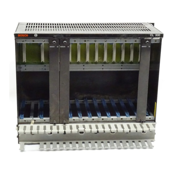
- Page 16 Configuration Flexible Automation 2.1.1 Card Cages A variety of card cages can be used for the CL300 Programmable Controller and its expansions to suit application specific requirements. 2.1.1.1 Card Cage BGT301 The BGT301 Card Cage is a 19" metal rack to accommodate 14 modules in dual Eurocard format.
- Page 17 Configuration Flexible Automation NT301 ZE301 Peripheral modules intelligent AG/P AG/P AG/Z system modules AG/P Peripheral bus System bus Cable duct 449.2 mm 19 " = 482.6 mm Top view Side view 200 mm Rear mounting brackets 354.8 mm Cable duct Cable duct Front mounting brackets...
- Page 18 Configuration Flexible Automation 2.1.1.2 Card Cage BGT301−K The BGT301−K Card Cage is a 11.8" wide metal rack to accommodate 8 modules in dual Eurocard format. Except for their different widths, the BGT301−K and the BGT301 are identical. The system bus runs from slot 3 to slot 6, permitting to accommodate 3 intelligent system modules in slots 4, 5, and 6 in addition to the central processing unit ZE301.
-
Page 19: Card Cage Bgt301−K
Configuration Flexible Automation NT301 ZE301 Peripheral modules intelligent AG/Z system modules AG/P Peripheral bus System bus 266.4 mm 11,8 " = 299.8 mm Top view Side view Rear mounting brackets 200 mm 354.8 mm Front mounting brackets Fan unit space Fig. - Page 20 Configuration Flexible Automation 2.1.1.3 Card Cage BGT300 The BGT300 Card Cage has the same dimensions as the BGT301 Card Cage. The difference is its shorter SYSTEM BUS, allowing only peripheral modules to be accommodated in the card cage, in addition to the power supply unit and the central processing unit.
- Page 21 Configuration Flexible Automation 2.1.2 Basic Unit GG301 The GG301 Basic Unit includes: BGT301 Card Cage NT301 Power Supply Unit in slots 1 and 2 ZE301 Central Processing Unit in slot 3 Up to three intelligent system modules in slots 4, 5, and 6, which are to be aligned left in the slot adjacent to the central processing unit.
-
Page 22: Basic Unit Gg301−K
Configuration Flexible Automation 2.1.3 Basic Unit GG301−K The GG301−K Basic Unit includes: BGT301−K Card Cage NT301 Power Supply Unit in slots 1 and 2 ZE301 Central Processing Unit in slot 3 Up to three intelligent system modules in slots 4, 5, and 6, which are to be aligned left in the slot adjacent to the central processing unit. - Page 23 Configuration Flexible Automation 2.1.4 Basic Unit GG300 The GG300 Basic Unit includes: BGT300 Card Cage NT300/301 Power Supply Unit in slots 1 and 2 ZE300 Central Processing Unit in slot 3 Peripheral modules in slots 4 to 14 The GG300 Basic Unit does not contain any intelligent system modules (only intelli gent peripheral modules) nor any AG/DZ Remote Expansion Module.
-
Page 24: Basic Unit Gg300−K
Configuration Flexible Automation 2.1.5 Basic Unit GG300−K The GG300−K Basic Unit includes: BGT300−K Card Cage NT300/301 Power Supply Unit in slots 1 and 2 ZE300 Central Processing Unit in slot 3 Peripheral modules in slots 4 to 8 The GG300−K Basic Unit does not contain any intelligent system modules (only in telligent peripheral modules) nor any AG/DZ Remote Expansion Module. - Page 25 2.1.6 Expansion Unit EG300 The EG300 Expansion Unit is used to expand the CL300. The EG300 Card Cage has the same overall dimensions as the BGT300/301 Card Cages. It contains a peripheral bus but no system bus and can accommodate the following modules.
- Page 26 Configuration Flexible Automation 2.1.7 Multi−shelf Configuration A multi−shelf configuration can be made up of a maximum of three shelves. Nor mally only one fan unit mounted in the lower unit is required for heat dissipation. To ensure easy installation and removal of the fan unit, sufficient clearance should be provided under the corresponding unit.
- Page 27 Configuration Flexible Automation If necessary, provide clearance 100 mm EG300 Expansion Unit Shelf 3 100 mm If necessary, provide clearance EG300 Expansion Unit Shelf 2 100 mm If necessary, provide clearance NT300/ GG300/301 Basic Unit Shelf 1 If necessary, provide clearance 100 mm Fig.
- Page 28 Configuration Flexible Automation 2.1.8 Fan Unit The use of a fan may be necessary to prevent heat accumulation, depending on the modules installed in the card cage. The fan unit consists of one fan for models BGT300−K/301−K or two fans for mod els BGT300/301 and a filter mat.
-
Page 29: Fan Unit Of Bgt300/301
Configuration Flexible Automation Top View É É É É É É É É É É É É É É É É É É É É É É É É É É É É É É É É É É É É É... - Page 30 Configuration Flexible Automation Removal Unlatch fan unit latches (7) in clockwise or counterclockwise direction and lower fan unit. Remove the power connector. Pull out fan unit towards the front. . Note , Unused slots should be covered with filler panels in order to ensure an optimum flow of cooling air. Specifications External Voltage Supply 24 V DC...
- Page 31 Flexible Automation 2.1.9 Fanless Operation Fanless operation of the CL300 is possible under the following conditions: Ambient temperature must not exceed 55 _C. Use of NT300 Power Supply Unit only. Sufficient flow of cooling air must be ensured to avoid heat accumulation.
-
Page 32: Card Cage Installation
Configuration Flexible Automation 2.1.10 Card Cage Installation The card cage can be mounted to a flat surface or in a rack, using the mounting brackets at the rear. When the two mounting brackets are attached to the front edges of the card cage, the controller can be installed in a cabinet (with a flush front panel). - Page 33 Maximum torque of the mounting screws is 0.5 Nm. 2.1.12 Expansions Several expansion options have been provided for the CL300 to meet various user− specific requirements. These options are described below. 2−21...
- Page 34 Configuration Flexible Automation 2.1.12.1 Central Expansion . Note , The GG300−K and GG301−K Basic Units allow for central expansions. Further information is available on re quest. A basic station as a result of central expansion includes one basic unit and a maxi mum of two expansion units.
- Page 35 Configuration Flexible Automation 2.1.12.2 Parallel Expansion Parallel expansion includes one basic station (1 basic unit and 2 expansion units) and one expansion station (3 EG300 Expansion Units in series) in a parallel configu ration. The illustration below shows the arrangement of the individual units, the AG/P Paral lel Expansion Unit, the AG/Z Central Expansion Unit and the connections required.
-
Page 36: Distributed Expansion
Configuration Flexible Automation 2.1.12.3 Distributed Expansion Distributed expansion ensures communication between the GS301/ 301−K Basic Station and several remote EWS300 Expansion Stations. Maximum distance from the basic station to the farthest expansion station is 800 m. Distributed expansion in its maximum configuration includes one basic station (1 x GG301/301−K and 2 x EG300) and 4 x 2 EWS300 Expansion Stations, connected to the distributed expansion station in GG301/301−K and forming two lines. -
Page 37: Expansion Module Slots
Configuration Flexible Automation 2.1.12.4 Expansion Module Slots The hatched sections in the table below show which basic and expansion units can accommodate expansion modules. The maximum number of expansion modules per card cage is not indicated in the table. Expansion Modules Options AG/DZ AG/DU... -
Page 38: Slots Of Individual Modules
Configuration Flexible Automation 2.1.12.5 Slots of Individual Modules . Note , The modules installed in slots 1, 2, and 3 of the GG300/301 Basic Units should be operated in the same slots in the GG300−K/301−K. The modules installed in the right slots of the GG300/301 are shifted 6 slots to the left in the GG300−K/301−K. - Page 39 Configuration Flexible Automation . Note , The modules installed in slots 9 to 14 of the GG300/301 are not applicable in the GG300−K/301−K Basic Units. EG300 GG300 GG301 EG300 Remote Expansion Unit Basic Unit Basic Unit Expansion Unit of the 1st expansion shelf Digital and 1 2 3 4 5 6 7...
-
Page 40: Wiring Diagram
Flexible Automation Electrical Configuration 2.2.1 Regulations The electrical connections of the CL300 Controller should comply with the regula tions VDE 0100 and VDE 0113. 2.2.2 External Power Supply Power for actuators and transducers is not supplied by the NT300/301 Power Sup ply Unit. - Page 41 Configuration Flexible Automation Specifications Input Voltage 380 V/3−phase/50 Hz Output Voltage 24 V DC to DIN 19240 Peak−to−average Ripple Factor Max. Output Current 6 A, 10 A, 20 A, 40 A Input Current at Nominal Load 0.3 A, 0.45 A, 0.83 A, 1.7 A Connecting Terminals (mm@) 1.5, 1.5, 2.5, 2,5 Protection Class...
- Page 42 Configuration Flexible Automation Cover plate Cover plate Fig. 2−17 Wiring Diagram (Example) 2.2.4 Power Consumption with Parallel Expansion The internal operating voltages for both input and output modules of all expansion types are supplied by an NT300 or NT301 Power Supply Unit, located in the basic unit.
- Page 43 2.2.5 Terminals and Connections The CL300 Controller is supplied with a line voltage of 220 V/230 V or 110 V/115 V AC at a line frequency of 47 to 63 Hz. The voltage is switch−selectable using switch S1 on the power supply unit (see paragraph 4.1.4).
- Page 44 Configuration Flexible Automation The link between basic unit and expansion unit or between several expansion units as well as the connections to computer interfaces, to programming units, to expan sion modules, etc., are made via preformed system cables with system connectors on both ends.
- Page 45 Operation Flexible Automation Contents Page Operation ........3−3 Program Execution .
- Page 46 ......3−4 3−2 Performance of the CL300 ..... . . 3−6...
- Page 47 Operation Flexible Automation Operation Program Execution The CL300 user program can be executed in cyclic, interrupt−controlled and time− controlled manner. Detailed descriptions of individual program execution steps are given in Chapter 5 Software Description". Organizational Structure The user program is stored in the CL300 RAM, EPROM or EEPROM.
- Page 48 Operation Flexible Automation Fig. 3−1 Organizational Structure 3−4...
- Page 49 Operation Flexible Automation Operating Modes The CL300 can operate in the RUN and STOP modes, which can be set on the ZE300/301 central processing unit. The start−up performance of the CL300 after power−on or from the stop state can be determined in the OM7 or OM8 Organizational Modules provided for that pur pose.
- Page 50 PROM STOP STOP STOP Fig. 3−2 Performance of the CL300 Process Image The states of the inputs/outputs is reflected in the process image which is updated following each cycle. When the input/output operands are entered with interface identifiers II/IO, direct peripheral operations can by−pass the process image.
- Page 51 Operation Flexible Automation The process image is updated. Direct addressing of the inputs/outputs is effected in byte−by−byte manner. 3−7...
- Page 52 Operation Flexible Automation 3−8...
- Page 53 System Modules Flexible Automation Contents Page System Modules ......4−5 Power Supply Units NT300/301 ....4−5 4.1.1 Function...
- Page 54 System Modules Flexible Automation Contents Page Output Modules ......4−44 4.4.1 Digital Output Modules .
- Page 55 System Modules Flexible Automation List of Illustrations Fig. Page 4−1 Power Supply Units NT300/301 ....4−8 4−2 Settings NT300/301 ......4−9 4−3 Buffer Battery NT300...
- Page 56 System Modules Flexible Automation List of Illustrations Fig. Page 4−26 A 24 V DC 0.5 A 16 outputs ..... 4−52 4−27 A 24 V DC 2 A 16 outputs .
-
Page 57: Power Supply Units Nt300/301
Power Supply Units NT300/301 Two different power supply units, NT300 and NT301, are used to provide the internal supply voltage for the CL300 controller. The NT300 Power Supply Unit is designed for use in the GG300/300−K Basic Unit operated without intelligent additional modules, and therefore consuming less power. - Page 58 Input voltage selection is not necessary with the NT301 because the NT301 auto−ranges to the respective input voltage. The power supply unit generates the following operating voltages for the CL300: +5 V for the logic circuits +12 V for the peripheral bus +12 V isolated for the interface 3.4 V for the program memory module...
- Page 59 Power failure The buffer battery integrated in the power supply unit provides a central supply of the CL300 memories which are to be buffered (retaining of remanent timers, counters, and markers) in case of a power failure. The power supply unit is supplied without buffer battery which must be ordered separately.
- Page 60 System Modules Flexible Automation 4.1.3 Front Panel Mounting Screws LED green: 5 V/ 12 V present 5/12 V 5/12 V + − 12 V LED green: ISO 12 V ISO 12 V (isolated) present Batterieausfall Batterieausfall LED red: Battery fault Rücksetzen Rücksetzen RESET button for...
-
Page 61: Settings Nt300/301
System Modules Flexible Automation 4.1.4 Settings Switch S1 for setting the voltages of 115 or 230 V AC, respectively, on the NT300. Voltage switch−over is performed automatically on the NT301. NT300 NT301 upper circuit board Fig. 4−2 Settings NT300/301 J1 for Floating Contact Position 1−2 for ZE in STOP and Power Failure Position 2−3 for Power Failure 4−9... - Page 62 System Modules Flexible Automation J2 for Buffer Battery Position 1−2 for Battery Out of Service Position 2−3 for Battery Operation Factory Settings Voltage switch in 230 V" position Jumper J1 in position 1−2 Jumper J2 in position 2−3 Battery not supplied 2−pin socket strip for floating contact, assembled 4−10...
- Page 63 Buffer Battery Installation and Replacement Caution If the buffer battery has been used for buffering remanent timers, counters and markers, it must be replaced when the CL300 is switched ON to retain buffered the remanent timers, counters and markers. Installation in the NT300 Unscrew the 2 Phillips screws and take out battery box (see Fig.
- Page 64 System Modules Flexible Automation Unscrew the 2 Phillips screws and take out battery box (see Fig. 4−3). Remove battery. Insert new buffer battery. (Observe the polarity!) Insert battery box and Phillips screws. Installation in the NT301 Unscrew buffer battery cap (1), see Fig. 4−4. Insert buffer battery (2).
-
Page 65: Buffer Battery Nt300
System Modules Flexible Automation 4.1.6 Specifications NT300 NT301 Input Voltage 220 V −15 % 230 V +10 % 115 V +10 % 110 V −15 % Frequency 47−63 Hz 47−63 Hz Line Voltage >187 V or >93 V, resp. Line Fuse M 1.6 A 230 V M 6.3 A 230 V Internal Supply Voltage... - Page 66 System Modules Flexible Automation 4.1.7 Ordering Information Order No. Power Supply Unit NT300 052 001 Power Supply Unit NT301 052 002 Buffer Battery for NT300 914 446 Buffer Battery for NT301 914 447 4−14...
- Page 67 ZE301 allows the use of intelligent system modules and remote expan sion units. 4.2.1 Function The ZE central processing unit is the heart of the CL300 Controller and has the following functions: Reading of input data Decoding and processing of the PLC instructions in the user pro...
- Page 68 System Modules Flexible Automation 4.2.2 Configuration The ZE300 or ZE301 Central Processing Unit occupies slot 3 of the basic unit. Power is supplied by the NT300 or NT301 Power Supply Unit. Power Supply Word System System Program Image Interfacing Processor Memory Processor Counters...
- Page 69 System Modules Flexible Automation Memory area for Input and output images Markers (Remanency selectable) Timers (Remanency selectable) Counters (Remanency selectable) Data buffers, remanent With remanency switched on in the ZE300/301, the remanent memory area for markers, timers and counters is buffered by the battery used in the NT300/301 in case of power failure.
- Page 70 System Modules Flexible Automation For fast fault isolation, status information is collected in an interrupt stack to permit reconstruction of the program flow. The following information can be requested using the PG4 Programming Unit. Absolute controller address Register contents of A, B, and C Status information Data module base address Module stack pointer...
- Page 71 System Modules Flexible Automation SM31.2 Flashing Indicator approx. 2 Hz SM31.3 Carry SM31.4 Forcing Marker SM31.5 Overflow SM31.6 Negative SM31.7 Zero All inputs/outputs can be forced, i. e. they can be overlaid by an arbitrary forcing mask. This forcing mask is entered by the programming unit. When forcing signals, the special marker SM 31.4 is set.
- Page 72 System Modules Flexible Automation 4.2.3 Settings V.24/20 mA Interface The serial data signal is transferred to the 25−pin D connector as V.24 and 20 mA signals. With the JP2 (see Fig. 4−6) jumper in position A, data transfer is made without a control signal.
- Page 73 System Modules Flexible Automation Setting of the Baud Rate The baud rate is set to the values in the table below, using the 8−seg ment DIP switch S1 (see Fig. 4−6). Transfer Rate DIP Switch Positions (Baud) Switch 1 Switch 2 Switch 3 1200 2400...
-
Page 74: Central Processing Units Ze300/301
System Modules Flexible Automation 4.2.4 Front Panel Mounting Screw Red LED "I/O forced" "Fix Reset" button Reset Red LED "ZE in Stop" Stop RUN/STOP Switch Ausg. "Inhibit outputs" Switch sperren "Remanency" Switch Rem. Status Status Display Memory Module Slot 25−pin D connector Mounting Screw Fig. - Page 75 System Modules Flexible Automation Red LED "I/O forced LED lights when a signal of any kind is forced. "Fix Reset" Fix Reset" button to delete all active forcings Red LED ZE in STOP" When the LED lights, program execution is stopped and all outputs are reset to zero.
- Page 76 System Modules Flexible Automation 4.2.5 Specifications +5 V, 5 %, 3050 mA max. (with EEPROM) Supply Voltage +5 V buffered, 5 %, 220 mA max. (operating) +12 V, 5 %, 100 mA max. (without I/O card) isolated +12 V, 5 %, 250 mA max. isolated −12 V, 5 %, 25 mA max.
- Page 77 System Modules Flexible Automation Humidity Class F to DIN 40 040 Dimensions Dual Eurocard format Inputs 512 with process image (I) I0.0−I63.7 512 directly with process image tracking (II) II0.0−II63.7 512 additional inputs (EI) EI0.0−EI63.7 Outputs 512 with process image (O) O0.0−O63.7 512 directly with process image tracking (IO) IO0.0−IO63.7 512 additional outputs (EO) EO0.0−EO63.7 Marker...
- Page 78 System Modules Flexible Automation Selectable Remanency Range in OM7: T0−T127 Counters Range: 0−8191 up/down 128 internal, C0−C127 Standard definition C0−C63 non−remanent C64−C127 remanent Selectable Remanency Range in OM7: C0−C127 Data Buffer 512 bytes, remanent DB0−DB511 RAM Buffering 1 year (central battery buffering in the power supply unit) 4.2.6 Ordering Information Order No.
- Page 79 System Modules Flexible Automation Input Modules Caution All specifications for input modules are referenced to operation with a fan unit. 4.3.1 Digital Input Modules Function The digital input modules are used for converting the external process signals to the internal signal levels. Configuration The input modules are available with 16 and 32 channels.
- Page 80 System Modules Flexible Automation see paragraph 4.3.1.1 4.3.1.2 4.3.1.3 4.3.1.4 4.3.1.5 Digital Input Modules Input Voltage 24 V DC 24 V DC 24 V DC 230 V AC 115 V AC Number of Inputs 2−pin − − − Frequency Range 47−63 Hz Logic "0"...
-
Page 81: Addressing Example
System Modules Flexible Automation Permissible Start Addresses Possible start addresses" are defined for addressing the input modules, depending on the number of input channels per module. The possible start addresses for the individual 16− and 32−input cards are listed in the table below. Inputs channels Permissible Start Addresses... - Page 82 System Modules Flexible Automation Two 24 V DC modules with 16 inputs each shall be allocated the ad dresses 4.0 through 7.7. Start address 4.0 is set on the first module using the DIL switch (see above). Start address 6.0 is set on the second module using the DIL switch. 1st Card Start Address 4.0 2st Card...
-
Page 83: E 24 V Dc 32 Inputs
System Modules Flexible Automation 4.3.1.1 E 24 V DC 32 inputs Pin Assignement Front Panel 24 V 24 V 24 V free 24 V Input Circuit E24− Input +12 V green +24 V free +24 V Fig. 4−12 E 24 V DC 32 inputs 4−31... -
Page 84: E 24 V Dc 16 Inputs
System Modules Flexible Automation 4.3.1.2 E 24 V DC 16 inputs Front Panel Pin Assignement 24 V 24 V 24 V free 24 V Input Circuit E24V− Input +12 V green +24 V free +24 V Fig. 4−13 E 24 V DC 16 inputs 4−32... -
Page 85: E 24 V Dc 16 Inputs 2−Pin
System Modules Flexible Automation 4.3.1.3 E 24 V DC 16 inputs 2−pin Pin Assignement Front Panel 24 V 24 V 24 V 24 V 24 V 24 V 24 V 24 V 24 V 24 V 24 V 24 V 24 V 24 V 24 V... -
Page 86: E 220 V Ac 16 Inputs 2−Pin
System Modules Flexible Automation 4.3.1.4 E 220 V AC 16 inputs 2−pin Pin Assignement Front Panel ß 220V ß 220V ß 220V ß 220V ß 220V ß 220V ß 220V ß 220V ß 220V ß 220V ß 220V ß 220V ß... - Page 87 System Modules Flexible Automation . Note , When using the E 220 V AC model, a fan unit should be installed in the card cage in the following cases. Permissible maximum configuration when using 220 V Units Without 220 V Unit 3rd Shelf (Expansion Unit EG300) No Fan Unit With...
-
Page 88: E 115 V Ac 16 Inputs 2−Pin
System Modules Flexible Automation 4.3.1.5 E 115 V AC 16 inputs 2−pin Pin Assignement Front Panel ß 115 V ß 115 V ß 115 V ß 115 V ß 115 V ß 115 V ß 115 V ß 115 V ß... - Page 89 System Modules Flexible Automation . Note , When using the E 115 V AC model, a fan unit should be installed in the card cage in the following cases. Permissible maximum configuration when using 115 V Units Without 115 V Unit 3rd Shelf (Expansion Unit EG300) No Fan Unit With...
- Page 90 The ZE interrupts the current PLC program and changes to the organiza tional module that is allocated to the interrupt input. Interrupt Operation in the CL300 When using the IE module for interrupt operation in the CL300 Controller, please note the following: 4−38...
-
Page 91: Input Address Range Ie 24− 16 Inputs
The PLC commands IR, IS, and IF are used to reset, inhibit or en able the interrupt inputs. The arithmetic registers A, B, C of the CL300 controller must be saved by the user, if necessary, after the jump to the interrupt or ganizational module. - Page 92 System Modules Flexible Automation 8 High−speed Inputs 8 High−speed or Interruptable Inputs IE24V− Input Protective Ground Connection 2−pin 24 V DC External Power Connector Fig. 4−20 High−speed Interruptable Input Module IE 24− 4−40...
- Page 93 System Modules Flexible Automation Slot With the exception of expansion units in distributed expansion, the IE module (interrupt mode) can be installed in any slot that accepts periph eral modules. . Note , A detailed description of the module is given in Technical Description" P .−No. 3913. Specifications External Supply Voltage 24 V DC to DIN 19240...
- Page 94 Max. Overcurrent: 70 mA Temperature Measurement using RTDs (e.g. PT100) 50 mV to 10 V Temperature Measuring Range Total R for all RTDs: 4.5 kW Number of Inputs 16 differential inputs 8 differential inputs with RTDs Maximum Number of Cards per CL300 4−42...
- Page 95 System Modules Flexible Automation Transducer Connection Two−wire connection Four−wire connection with RTDs Wiring Twisted pair, shielded Max. Cable Length 200 m Constant Current Source 2 mA for RTD measurements Power Supply 24 V DC to DIN 19 240 Current Consumption 150 mA internal 300 mA external Slot...
- Page 96 System Modules Flexible Automation Output Modules Caution All specifications for output modules are referenced to operation with a fan unit. 4.4.1 Digital Output Modules Function The digital output modules convert the internal signal levels to the exter nal process signals. Configuration 8−channel, 16−channel, and 32−channel output modules are avail able.
- Page 97 System Modules Flexible Automation Specifications see paragraph 4.4.1.1 4.4.1.2 4.4.1.3 4.4.1.4 4.4.1.5 Digital Output Modules Nominal Voltage 24 V DC 24 V DC 24 V DC 24 V DC 24 V DC Permissible Voltage Range 20.4 V−28.8 V and 5 % Ripple factor from to DIN 19240 superimposed AC Number of Outputs...
- Page 98 System Modules Flexible Automation see paragraph 4.4.1.6 4.4.1.7 4.4.1.8 4.4.1.9 Digital Output Modules Aux. voltage Nominal Voltage 24 V DC 24 V DC 230/115 V AC 24 V DC 20.4 V−28.8 V +15 % −20 % 20.4 V−28.8 V Permissible Voltage Range and 5 % and 5 % to DIN 19240...
- Page 99 System Modules Flexible Automation Continuation see paragraph 4.4.1.6 4.4.1.7 4.4.1.8 4.4.1.9 Digital Output Modules Relay Contact Voltage max. 220 V AC Relay Contact Switching 140 W/ 500 VA Capacity Contact Resistance max. Contact Bounce max. 1 ms Max. Switching Frequency resistive 20 Hz inductive...
- Page 100 System Modules Flexible Automation Addressing Output modules are hardware−addressed. Possible start addresses for the individual 8−channel, 16−channel and 32−channel O modules are listed in the following table. An addressing example is explained in paragraph 4.3.1. n−channel Permissible Start Addresses O card Fig.
- Page 101 System Modules Flexible Automation 4.4.1.1 A 24 V DC 0.2 A 32 outputs Pin Assignement Front Panel A24/0,2− Input 24 V 24 V 24 V 24 V 24 V 24 V Output Circuit U2 = 6 V 24 V 24 V 24 V Actual Current Detection Short−proof Output Driver...
- Page 102 System Modules Flexible Automation 4.4.1.2 A 24 V DC 0.5 A−e 32 outputs short−circuit proof Front Panel Pin Assignement A24/0,5− Input 24 V 24 V 24 V 24 V 24 V 24 V Output Circuit External 24 V 1 2 3 red/error Internal 0 V 1 2 3...
- Page 103 System Modules Flexible Automation Protection The outputs are protected against: Polarity reversal (24 V DC) Short−circuit Overload. In all these cases, the LED error indicator lights. In case of a short−circuit or overload the respective output is deactivated. After 2 ms the output is reactivated.
- Page 104 System Modules Flexible Automation 4.4.1.3 A 24 V DC 0.5 A 16 outputs Front Panel Pin Assignement 24 V 24 V A24/0,5− 24 V 24 V Output 24 V 24 V Output Circuit External 24 V External 24 V External 24 V FF 0.63 A Internal 0 V External 0 V...
- Page 105 System Modules Flexible Automation 4.4.1.4 A 24 V DC 2 A 16 outputs Front Panel Pin Assignment 24 V 24 V A24/2− 24 V 24 V Output 24 V 24 V Output Circuit External 24 V External 24 V External 24 V FF2.5 A Internal 0 V External 0 V...
- Page 106 System Modules Flexible Automation 4.4.1.5 A 24 V DC 2 A−e 16 outputs Front Panel Pin Assignment checksum error LED 24 V 24 V 24 V 24 V A24/2−e 24 V 24 V Output Output Circuit External 24 V Error Message Internal 0 V Output 0 1 2 3...
- Page 107 System Modules Flexible Automation 4.4.1.6 A 24 V DC 2 A 8 outputs Front Panel Pin Assignment 24 V 24 V 24 V 24 V 24 V 24 V A24/2−e Output External 24 V Input Circuit External 24 V External 24 V FF 2.5 A Internal 0 V External 0 V...
- Page 108 System Modules Flexible Automation 4.4.1.7 A 24 V AC 2 A 2−pin 16 outputs Pin Assignment Front Panel 24 V 24 V 24 V 24 V 24 V 24 V 24 V 24 V 24 V 24 V 24 V 24 V 24 V 24 V...
- Page 109 System Modules Flexible Automation 4.4.1.8 A 230/115 V AC 2 A electronic 8 outputs The module is designed to operate with 230 V and/or 115 V supply volt age. Voltage can be selected using the voltage switch (S1/2) on the mod ule.
- Page 110 System Modules Flexible Automation 4.4.1.9 AR 220 V AC 2 A Relay 16 outputs 2−pin 24 V DC auxiliary voltage Pin Assignment Front Panel 220 V 220 V 220 V 220 V 220 V 220 V 220 V 220 V 220 V 220 V 220 V...
- Page 111 10 V, 5 V, 2.5 V Specifications Voltage Ranges 20 mA, 10 mA, 5 mA Current Ranges Number of Outputs Max. Number of Cards per CL300 Wiring Twisted pair, shielded Max. Cable Length 200 m U: 500 W, I: 500 W Max.
- Page 112 System Modules Flexible Automation 24 V DC 20 % Supply Voltage Current Consumption int. 80 mA max. ext. 300 mA max. Width 1 module width . Note , The outputs assume a defined state in case of controller power failure. Analog output modules require the use of a fan unit in the card cage.
-
Page 113: Central Expansion
Fig. 4−33 Central Expansion Module AG/Z Function The AG/Z Expansion Module is designed for centralized expansion of the CL300. It provides the internal operating voltages and the peripheral bus for the expansion units. Configuration Up to 2 expansion units are connected to a basic unit or remote expan sion unit, depending on the configuration. - Page 114 System Modules Flexible Automation Connection The connection is made through a 0.55 m cable and the two 50−pin fe male connectors on the module front panel. These two connectors are connected in parallel so that the connection can optionally be made us ing the upper or the lower connector.
- Page 115 System Modules Flexible Automation Parallel Expansion Module AG/P AG/P Fig. 4−34 Parallel Expansion Module AG/P Function In addition to central expansion, the AG/P Parallel Expansion Module adds length to the peripheral bus, using drivers and short cables. It per mits the use of a larger number of expansion units. Configuration It is possible to use up to 3 AG/Ps in the basic unit.
-
Page 116: Parallel Expansion
System Modules Flexible Automation Parallel expansion may include one basic station (1 GG Basic Unit con nected in series with 2 expansion units) and up to 3 expansion stations (3 expansion units each). Connection The AG/P Expansion Module is connected to the expansion station with 0.55 m or 1.8 m standard interconnection cables. - Page 117 System Modules Flexible Automation Remote Expansion Modules AG/DZ and AG/DU Bereit Ready AG/DU AG/DZ T2,5A Fig. 4−35 Remote Expansion Modules AG/DZ and AG/DU Function Large geographical distances between the installations to be controlled usually result in extensive wiring. This wiring effort can be reduced with a distributed architecture of the input/output units, and only a shielded twisted−pair cable is required.
- Page 118 System Modules Flexible Automation Configuration To implement distributed expansion, the AG/DZ Expansion Module is centrally installed in the basic unit, and the AG/DUs are remotely in stalled in the expansion units.Distributed expansion requires the use of the GG301/301−K Basic Unit. A maximum of 2 expansion lines can be connected to each AG/DZ.
- Page 119 1, 2, 13, or 14 in the expansion unit, depending on the ex pansion configuration, see paragraph 2.1.12.5. Specifications Max. Number of AG/DZs per CL300 Max. Number of AG/DUs per Expansion Line (EWL) Max. Transmission Distance between AG/DZ...
- Page 120 System Modules Flexible Automation Width 1 module width . Note , A detailed description of the AG/DZ and AG/DU Modules is given in Module Description" P .−No. 3815. Ordering Information Order No. AG/DZ 048 093 Revision 2 or later AG/DU 048 166 Revision 2 or later Connector Kit for 1 cable 048 983...
- Page 121 Intelligent Peripheral Modules In addition to the use of the intelligent system modules R301 and DB301, the CL300 permits the use of intelligent peripheral modules which, how ever, can only be connected to the peripheral bus. Among these are the following: PU401 Positioning Unit (description P .−No.
- Page 122 System Modules Flexible Automation 4−70...
- Page 123 Software Description Flexible Automation Contents Page Software Description ..... 5−3 Program Structure ......5−3 5.1.1 Organizational Modules OM...
-
Page 124: Software Description
Example of programming Program Modules ..5−5 5−4 Flow diagram of the CL300 ..... 5−7 5−5 Start−up performance... -
Page 125: Program Structure
Flexible Automation Software Description Program Structure Due to its modular design, the CL300 controller allows the user to break up his/her program into functional blocks, i. e. to achieve a clearly struc tured program. Different module types are available. The CL300 uses the following module types:... -
Page 126: Organizational Modules Om
The user can determine programs in the different organizational mod ules to be executed in response to certain events, e.g. time sequences, start−up behavior, etc. 9 organizational modules are available for the CL300: for cyclic program flow OM2 to OM4 for interrupt control via the inputs EI1.0−EI1.2... -
Page 127: Program Modules Pm
Software Description Flexible Automation 5.1.2 Program Modules PM The program modules contain program segments which are related with respect to their technological or functional features, e.g. program mod ules for tool changers, transfer units, etc. From a program module, other program modules and data modules can be called. -
Page 128: Data Modules Dm
Software Description Flexible Automation 5.1.3 Data Modules DM Data modules may contain all fixed and variable data defined by the user as well as texts and messages. By means of the start−up organizational modules OM7 and OM8, the user can copy any data module from the user program memory to a data buffer range DB. -
Page 129: Program Flow
Program Flow Power ON Start−up Performance Servicing of Expansion and User Program Cyclic System Modules as well as PM/DM Time− Programming unit controlled Interrupt− Calls controlled Updating of Error Input/Output Detection Images STOP Fig. 5−4 Flow diagram of the CL300 5−7... - Page 130 Software Description Flexible Automation Start−up Performance When the CL300 controller is switched on, the system hardware in the central processing unit is checked (approx. 2 sec.). The following units are function−tested: Image RAM Operating RAM Operating EPROM Central battery 7−segment display...
- Page 131 Software Description Flexible Automation POWER ON Process Image is cleared Output are reset to zero Allocation List is generated Software STOP Check: e.g. Command Battery Fault "HLT" Error STOP Mode Detection Battery Replacement Reset STOP Mode "Battery Fault" Check: Error of System STOP−...
- Page 132 Software Description Flexible Automation I/O Allocation List On start−up following power on", an I/O allocation list is automatically generated. This list specifies which module type is allocated to the indi vidual modules. This actual allocation list can then be compared to a set allocation list that can be programmed in OM7.
-
Page 133: Program Execution
Software Description Flexible Automation Program Execution Program execution is defined in the organizational modules. The user can influence the system performance, e.g. start−up, by means of the available OMs. Events like error detection, interrupt inputs and time− outs during program execution result in the automatic call of the respec tive organizational module. -
Page 134: Cyclic Program Execution
Software Description Flexible Automation 5.3.1 Cyclic Program Execution The modules of the user program are executed according to the se quence specified in the OM1 organizational module. OM1 is automati cally called by the system after start−up. I/O Update Fig. 5−7 Cyclic Program Execution 5.3.2 Interrupt−controlled Program Execution When a positive edge of one of the special interface input interrupt sig... -
Page 135: Time−Controlled Program Execution
Software Description Flexible Automation I/O Update PM10 Time when an interrupt input EI1.0 occurs: Positiv edge 0 Fig. 5−8 Interrupt−controlled Program Execution 5.3.3 Time−controlled Program Execution The organizational modules OM5 and OM6 are processed using a predeterminded time base (factor * 10 ms, 10 min max.). For this pur pose, cyclic program execution is interrupted only between two program module calls (on module call or end of module) and is resumed at the point of interruption when the processing is terminated. -
Page 136: Definition Of Variables In Om7
Software Description Flexible Automation Program execution With 10 ms time base without time control Program Program Execution Execution Time Time Part of É É É Wait− É É É Time É É É É É É É É É É É É É É É É É... - Page 137 Software Description Flexible Automation Example ;Comparison of allocation lists desired K0002H,B ;Load K0002H to register B B,S0 ;Copy data module to DB K0004H,B B,S0 X : arbitrary Fig. 5−10 Control Word S0 Cycle Time S2 Main software watch dog (factor * 10 ms) Default approx.
- Page 138 Software Description Flexible Automation Time Base 2 S6 Time base for time−controlled program execution in OM6 (factor * 10 ms, 10 min max.) Default inactive (0) Example ;Factor definition in OM7 K600D,B ;Time base = 6 s B,S6 Data Module S8 Length and number of the data module to be copied to DB (Data Buffer) Default Length and number = 0...
- Page 139 Software Description Flexible Automation Byte number X : arbitrary Marker Range Non−remanent Range M100 Entry in S10: K101D M101 Remanent Range M255 Fig. 5−12 Marker Remanency S10 Time Remanency S12 Limiting (byte) address for timer remanency Default Byte 0−7 non−remanent (T0−T63) Byte 8−15 remanent (T64−T127) Example ;Definition of the timer remanency limit...
- Page 140 Software Description Flexible Automation Counter Remanency S14 Limiting (byte) address for counter remanency Default Byte 0−7 non−remanent (C0−C63) Byte 8−15 remanent (C64−C127) Example ;Definition of the counter remanency limit K2H,B ;C16 = 1st remanent counter B,S14 Allocation Lists S16−S46 Set allocation lists for input and output modules. Default no set allocation list defined Allocation...
-
Page 141: Programming Language
Software Description Flexible Automation Programming Language 5.4.1 Control Command Structure The control commands are executed in accordance with DIN 19239. They comprise an operation part and an operand part. The control command may also consist of the operation part only, e.g. open brackets (, end of program (EP). -
Page 142: Data Formats And Register Structure
Software Description Flexible Automation 5.4.2 Data Formats and Register Structure Bit−No. Ç Ç Ç Ç Bit = B Ç Ç Ç Ç Ç Ç Ç Byte = BY Ç Ç Ç Ç Ç Ç Ç Ç Ç Ç Ç Ç Ç Ç Ç Ç... -
Page 143: Addressing Modes
Software Description Flexible Automation 5.4.3 Addressing Modes Register − Register Example The content of register A is loaded into register B. ACCU A Register B Register C Fig. 5−18 Register − Register Register − Direct Example E15,B The content of a peripheral address is loaded into a register. ACCU A Register B 15.7 .... - Page 144 Software Description Flexible Automation ACCU A Register B Constant Register C Fig. 5−20 Register − Immediate Register Indirect Example [C],A Register A is loaded with the peripheral content whose address is in reg ister C. ACCU A Register B Peripheral Address Register C Fig.
-
Page 145: Address Ranges
Software Description Flexible Automation 5.4.4 Address Ranges Operand Byte Address Word Address Bit Address − Even byte 0.0 − 63.7 II/IO − addresses EI/EO − only − − 255.7 − − 127D − 127D − 28.0 − 31.7 − − −... - Page 146 Software Description Flexible Automation SM28.0−28.7 Error Byte SM28.0 Module Stack Error SM28.1 Opcode Error SM28.2 Addressing Error SM28.3 Module Management Error SM28.4 Controller Addressing Error SM28.5 Parameter Error SM28.6 C/T Set−point Error SM28.7 Cycle Time Error System Range Code List S0 (Bit 1) I/O allocation list desired S0 (Bit 2)
- Page 147 Software Description Flexible Automation Absolute Address Allocation The following list shows the structure of indirect addresses which are en tered in register C. from − to 0000 000F Counter states of counter bytes 0−15 0010 001F Timer states of timer bytes 0−15 0020 003F Special marker bytes SM0−SM31...
-
Page 148: Programming Considerations
Online Programming The programming unit is connected to a plug−in terminal on the central processing unit of the CL300. Then, the program can be loaded into the controller RAM or EEPROM memory and tested. Program amendments or modifications can be made during program execution. -
Page 149: Program Documentation
Software Description Flexible Automation Offline Programming Offline programming is made with the programming unit but without a connection to the CL300. The sequence is as follows: Program generation Storage on a floppy disk Documentation Program transfer to an EPROM memory module (in preparation) -
Page 150: Program Testing
5.5.3 Program Testing Program testing is performed directly on the CL300 Programmable Con troller. Program testing permits to check the link conditions of the individual cir cuit paths for their logic function through the status indications of the in put and output signals. - Page 151 Software Description Flexible Automation Program Flags Using the command * n (n = 0 − 31), the user can store program flags in the program flow stack of the interrupt stack. These program flags reflect the program flow prior to program abortion. The program flags can be set by the user at arbitrary points of the pro gram.
- Page 152 Software Description Flexible Automation 5−30...
- Page 153 Preparation for Use Flexible Automation Contents Page Preparation for Use ..... . . 6−3 6−1...
- Page 154 Preparation for Use Flexible Automation 6−2...
- Page 155 Preparation for Use Flexible Automation Preparation for Use Before operating of the CL300, please check the following: Make sure that the system configuration complies with the regula tions VDE 0100 and 0113 (see chapter 2.2 Electrical Configura tion). Check for correct jumper settings on the modules.
- Page 156 Enter the program and then load it into the controller. Select RUN" mode. Test the program and modify it, if necessary. Switch on the power circuit of the outputs. Reset Ausgänge sperren" (Inhibit outputs) function. The CL300 controller is now ready for operation. 6−4...
- Page 157 Maintenance Flexible Automation Contents Page Maintenance ......7−3 Buffer Battery Replacement .
- Page 158 Maintenance Flexible Automation List of Illustrations Fig. Page 7−1 Fan Unit − Front View ......7−4 7−2...
- Page 159 Flexible Automation Maintenance Buffer Battery Replacement The buffer battery should be replaced in the following cases with the CL300 controller is switched on: After one year of operating time. When the special marker SM31.1 Preventive battery fault indica tion" is set.
- Page 160 Maintenance Flexible Automation Fan Unit Filter Replacement The filter should be regularly inspected for contamination and be re placed, if necessary. Fan Unit − Front View 7 − Fan unit latch 8 − Filter mat latch 9 − Filter mat holder 11 −...
- Page 161 Maintenance Flexible Automation Press latch (8) to latch. Install fan unit as described in paragraph 2.1.8. 7−5...
- Page 162 Maintenance Flexible Automation 7−6...
- Page 163 Specifications Flexible Automation Contents Page Specifications ......8−3 8−1...
- Page 164 Specifications Flexible Automation 8−2...
- Page 165 Specifications Flexible Automation Specifications Ambient Temperature 0 to +55 _C Non−operating Temperature −20 to +70 _C Humidity Class F to DIN 40 040 Mechanical Stress Installation in stationary equipment, not free from vibration Mounting Dimensions 19 " for standard cabinets H = 354.8 mm, W = 482.6 mm, D = 200 mm Including cable duct D = 262.5 mm 11.8 "...
- Page 166 Specifications Flexible Automation Line Fuse M 1.6 A/230 V for NT300 M 6.3 A/230 V for NT301 Signal Voltages 24 V DC 115/230 V AC Load Currents 2 A max. per output 8−4...
- Page 167 1070 072 113-101 (89.02) GB · HB SP · AT/VSP · Printed in Germany...