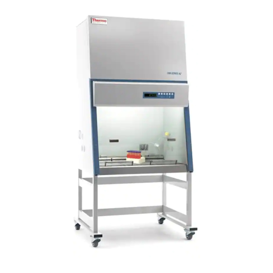
Thermo Scientific 1300 Series Operating Manual
Biological safety cabinet
Hide thumbs
Also See for 1300 Series:
- User manual (130 pages) ,
- Operating manual (72 pages) ,
- Installation manual (10 pages)

Related Manuals for Thermo Scientific 1300 Series


Summary of Contents for Thermo Scientific 1300 Series
- Page 1 1300 Series A2 Class II, Type A2 Biological Safety Cabinet Operating Manual 7021355 Rev. 18 Visit us online to register your warranty www.thermoscientific.com/labwarranty...
- Page 2 Containment * Comfort * Convenience™ The 1300 Series A2 offers a unique range of product features that will enhance your safety and improve overall operating efficiency. Should you have any questions on using this product or need further explanation of any of it’s features, please contact Technical Services (Page iv), or your local distributor.
- Page 3 In no event shall Thermo Fisher Scientific be held liable for any damages, direct or incidental, arising out of or related to the use of this manual. © 2020 Thermo Fisher Scientific. All rights reserved. 1300 Series A2 Thermo Scientific...
- Page 4 Always use the proper protective equipment (clothing, gloves, goggles, etc.) Always dissipate extreme cold or heat and wear protective clothing. Always follow good hygiene practices. Each individual is responsible for his or her own safety. Thermo Scientific Thermo Scientific 1300 Series A2...
- Page 5 We can also provide you with a quotation on our Extended Warranty for your Thermo Scientific products. Whatever Thermo Scientific products you need or use, we will be happy to discuss your applications. If you are experiencing technical problems, working together, we will help you locate the problem and, chances are, correct it yourself...over the telephone without a service...
-
Page 6: Table Of Contents
Unit Disposal ......... . .4-7 Thermo Scientific 1300 Series A2... - Page 7 Data Log/Warranty ......... . .9-1 1300 Series A2...
-
Page 8: Description
Description Section 1 Figure 1-1. Unit Components The Thermo Scientific 1300 Series A2 offers innovative SmartFlow™ technology; an automatic airflow compensation system that adjusts motor speed as filters load, without the use of a manual damper. The SmartFlow™ system ensures safe working conditions, even between annual certifications. -
Page 9: Safety Systems
Steady airflow within the air system ensures constant downflow, allowing the HEPA filters to remove contaminants so that the samples are always surrounded by ultra-pure air. Harmful particles are not carried over the sample chamber (protection from cross-contamination). 1300 Series A2 Thermo Scientific... - Page 10 Yellow or red indicators show that while the cabinet is providing personnel and product protection, maintenance should be scheduled to restore the compensation reserve. Thermo Scientific 1300 Series A2...
-
Page 11: Hepa Filters
These grids prevent large items such as paper towels and tissues from entering the plenum where they may impair the function of the blowers or the filters. The grids can be easily removed for cleaning. 1300 Series A2 Thermo Scientific... -
Page 12: Control Panel
Downflow and inflow air velocities • Remaining time of the UV disinfection routine The keys turn functions on or off. Status indicators show: • Window work position • Airflow • Reduced blower speed • SmartFlow Indicator Thermo Scientific 1300 Series A2... -
Page 13: Use Of The Window
Note The working and loading window positions are indicated on the user interface, as controlled by micro switches and displayed by status indicators on the control panel. Window 1300 SERIES A2 Max opening for loading samples Work position... - Page 14 UV light will not function. dimple Figure 1-5. Work Position Figure 1-6. Lighted Green LED dimple Figure 1-7. Fully Closed Position (UV, if applicable) Figure 1-8. Lighted Blue LED Thermo Scientific 1300 Series A2...
-
Page 15: Unit Interface
Warning If a gas burner is to be operated in the sample chamber, an appropriate shut-off valve for the gas supply must be installed. Use only laboratory safe burners in the sample chamber. 1300 Series A2 Thermo Scientific... -
Page 16: Chamber Lighting
Service valve Figure 1-9. Interfaces (2 of 4 access ports are shown) The Thermo Scientific 1300 Series A2 offers a bright workspace for a Chamber Lighting more comfortable working environment. Models with coated rear and side walls resist glare and make it easier for the user to work safely. -
Page 17: Uv Lights
To attach the armrests, insert into the first perforated track of the work tray. Warning Work safety is assured only if the armrests are used correctly! Work tray Perforation track Width Armrest Separation Depth distance Perforation Armrest track Figure 1-11. Work tray 1-10 1300 Series A2 Thermo Scientific... -
Page 18: Installation
When positioning the cabinet, make sure the counterweight on the back of the unit can move freely. The minimal distance to the wall or adjacent objects should be 3 inches (7.6 cm), unless upper wall brackets are used. Thermo Scientific 1300 Series A2... -
Page 19: Optional Exhaust Transition
3. Secure the accessory by tightening Threaded inserts the supplied retaining screws (M5) wrench-tight. 4. Using the adjustment nuts on the sliding panel, set the gap height to an opening of 2 inches. Figure 2-1. 4 ft Thimble 1300 Series A2 Thermo Scientific... - Page 20 3. Seal the unused connecting opening with Pipe the cover. Place the cover onto the connecting Sleeve opening at the housing Cover and secure it with the Sleeve screws. Opening Figure 2-2. 6 ft Thimble and Sleeve Thermo Scientific 1300 Series A2...
-
Page 21: Moving The Unit
Warning The weight of the window is balanced by the counterweight on the back of the cabinet. Do not move the unit unless the counterweight has been locked in place with the shipping screws (see Figure 3-2). Figure 2-3. Lift points 1300 Series A2 Thermo Scientific... -
Page 22: Service Valve Connections
7. Secure the service valve to the side panel using the nut. 8. Establish the connection to the supply line using a union nut. Note If a service valve is removed, the service valve port plug should be re-installed. Thermo Scientific 1300 Series A2... - Page 23 If SmartPorts are installed, replace the SmartPort grommet before starting a decontamination procedure. Two replacements (P/N 114111) are Before Decontamination shipped with each unit, or the 1910112 kit containing 4 grommets can be ordered. SmartPort locations are indicated above (one on each side). 1300 Series A2 Thermo Scientific...
-
Page 24: Universal Piping Connections
On 3 cu ft units, the right side access points are next to the right side rope channel. The left side access points are to the left of these. Figure 2-6. Possible Universal Piping Access Points/Drain Valve Thermo Scientific 1300 Series A2... -
Page 25: Smartport
Section 2 Installation SmartPort The SmartPort is an optional feature on the 1300 Series A2, designed to improve work area organization inside the biological safety cabinet. It is designed to accommodate the routing of vacuum line tubing, line cords and data cables from the interior of the cabinet to the exterior working area, freeing up space inside the work area. -
Page 26: Start-Up
5. To install the cabinet frame to the stand, insert four flatwashers and Allen screws loosely into the threaded holes at the bottom of the cabinet. Thermo Scientific 1300 Series A2... - Page 27 7. Slide the cabinet frame to the keyhole stop (see Figure. 3-1). 8. Tighten the four Allen screws. 9. Level the cabinet (instructions follow in this section). 1300 Series A2 Thermo Scientific...
-
Page 28: Unlock Counterweight
Check from right to left, and from back to front. Thermo Scientific 1300 Series A2... -
Page 29: Power Connection
Press and hold the On button. A green LED in the display indicates power is being supplied to the cabinet. The cabinet is now ready for operation and can be operated using the control panel. 1300 Series A2 Thermo Scientific... -
Page 30: Installation Tests
Caution Alarms on this unit are not factory-set. Set the alarms to avoid product loss and ensure personnel safety. Refer to Certification section. Thermo Scientific 1300 Series A2... -
Page 31: Locating A Certifier
PO Box 130140 789 N. Dixboro Rd Ann Arbor, MI 48113-0140 Telephone (734) 769-8010 Or (800) NSF-MARK Fax (734) 769-0109 http://www.nsf.org/Certified/Biohazard-Certifier IAFCA PO Box 12155 Columbus, OH 43212 Telephone (888) 679-1904 Fax (614) 486-1108 http://www.iafca.com/certifier.html 1300 Series A2 Thermo Scientific... - Page 32 Telephone (919) 787-5181 Fax (919) 787-4916 http://www.cetainternational.org/members/corp_indiv.htm Note Unless certification was expressly called for in the specification, quotes and/or purchase order, the cost for this on-site testing is to be paid for by the customer. Thermo Scientific 1300 Series A2...
- Page 33 Section 3 Start-Up 1300 Series A2 Thermo Scientific...
-
Page 34: Operation
• With UV light (optional) timer on, the remaining disinfection time. *Press the Hours/Velocities key to switch between the operating hours, and the downflow and inflow in safe work mode (with window in the open, safe operating work position). Thermo Scientific 1300 Series A2... - Page 35 This key also activates the UV disinfection procedure. During the procedure, the display alternates between dIS and the remaining preset time (see Section 5 to change this preset). Silence key for muting the audible alarm. 1300 Series A2 Thermo Scientific...
-
Page 36: Unit Start-Up
The green LEDs “front window is in work position” and “airflow steady” are lighted. The markings on the side guide rails and the lower edge of the front window are at the same height with no audible alarm signal. Thermo Scientific 1300 Series A2... -
Page 37: Loading The Chamber
4. Load the work tray with samples. 5. For work breaks or for extended experimental phases without manual intervention, switch the device to standby mode by closing the window. 1300 Series A2 Thermo Scientific... -
Page 38: Error Codes
• Do not place accessories into the sample chamber that cause air turbulence or emit excessive heat. • Do not block air circulation at the ventilation slots of the work tray. Thermo Scientific 1300 Series A2... - Page 39 After completing a procedure, 1. Remove samples from the sample chamber and store them properly. 2. Clean and disinfect the sample chamber surfaces, including the work tray and the drain pan. 3. Clean and disinfect all accessories. 1300 Series A2 Thermo Scientific...
-
Page 40: Unit Shut-Down
Warning As this unit can be used for processing and treating infectious substances, it must be decontaminated prior to disposal, in accordance with acceptable standards and procedures. Thermo Scientific 1300 Series A2... - Page 41 Section 4 Operation 1300 Series A2 Thermo Scientific...
-
Page 42: Cleaning / Decontamination
The presence of any liquid or solid that remains in contact with the stainless steel for a prolonged time can prevent oxygen contact and promote corrosion, as can prolonged contact with cleaners or disinfectants containing chlorine, ammonia, iodine or other caustic agents. Thermo Scientific 1300 Series A2... -
Page 43: Cleaning And Caring For Coated Surfaces
Never use abrasive cleaners, scouring pads or steel wool. If the coated surfaces do become dull, streaked, smeared or marred in some other way, there is no known method to restore the finish. 1300 Series A2 Thermo Scientific... -
Page 44: Disinfection
2. Press the UV key on the control panel. The display alternates between dIS and the remaining disinfection time. To interrupt or cancel the UV disinfection procedure, just press the UV key (the display shows the operating hours) and slide the window up. Thermo Scientific 1300 Series A2... -
Page 45: Change The Uv Disinfection Time
. Thermo Fisher Scientific has developed validated procedures for the decontamination of the Thermo Scientific 1300 Series A2 using the Steris VHP (Vaporized Hydrogen Peroxide) system. These procedures are available on request. -
Page 46: Clean Exterior Surfaces
3. Wipe the drain pan, using a clean cloth and plenty of clean water. 4. Discard any liquid in the drain pan. Rinse and dry thoroughly. Note After cleaning, make sure that all cleaning product has been removed completely from the drain pan. 5. Re-install the work tray. Thermo Scientific 1300 Series A2... -
Page 47: Clean The Paper Catch Grid
Retaining down and towards the back until the locking tabs are secured behind the inner back wall. Caution Do not operate the unit without the paper catch grids installed! Figure 5-1. Protective Paper Catch Grid 1300 Series A2 Thermo Scientific... -
Page 48: Maintenance
1. As a reminder, Thermo Fisher has specifically designed our sash to jam if the glass attachment point fails. Consequently, if the sash Jams or seems sluggish to move, do not use force! Contact your local distributor immediately. Thermo Scientific 1300 Series A2... -
Page 49: Service
The UV light should be replaced after 1500 operating hours. See Figure 6-1. 1. Turn the unit off and disconnect it from the power source. 2. Move the window to the maximum open position. 1300 Series A2 Thermo Scientific... -
Page 50: Replacements And Repairs
Caution Remote alarm systems can be retrofitted and integrated into the Repairs unit controls. Alarm contacts change state based on window position. Airflow changes from window position could impair personnel and product protection. Installation of these systems should only be performed by authorized service personnel. Thermo Scientific 1300 Series A2... -
Page 51: Unit Disposal
Warning As this unit can be used for processing and treating infectious substances, it may become contaminated. Prior to disposal, the entire unit with filters must be decontaminated in accordance with acceptable standards and procedures. 1300 Series A2 Thermo Scientific... -
Page 52: Specifications
Distance from back panel SmartPort mm / in 182.9 / 7.2 First access port mm / in 259.0 / 10.2 Second access port mm / in 309.9 / 12.2 Third access port mm / in 360.7 / 14.2 Thermo Scientific 1300 Series A2... - Page 53 Remaining upper ports - mm / in 226.1 / 8.9 Distance edge Remaining lower ports - mm / in 353.1 / 13.9 Distance lower edge Declaration of Conformity available from the factory, on request. 1300 Series A2 Thermo Scientific...
- Page 54 6ft models 10”: 65, ±2 Noise level* dB(A) 4ft. models 8": 62, ±2 6ft. models 8": 64, ±2 *The noise level was determined in accordance with NSF/ANSI 49. The measurement uncertainty is within a range of ± 2 dB. Thermo Scientific 1300 Series A2...
- Page 55 5ft models 10”: 65, ±2 Noise level* dB(A) 3ft. models 8": 62, ±2 5ft. models 8": 64, ±2 *The noise level was determined in accordance with NSF/ANSI 49. The measurement uncertainty is within a range of ± 2 dB. 1300 Series A2 Thermo Scientific...
- Page 56 UL61010-1) Connecting lines Power Cord (>3 m / 10 ft) Mains connection CEE 7/7 Plug with NEMA 5-15 plug * With additional 5A load on cabinet receptacles, blowers at 100% and cabinet lighting switched on. Thermo Scientific 1300 Series A2...
- Page 57 / in 107 / 4.2 Exhaust air Height mm / in 610 / 24 457 / 18 Length mm / in 457 / 18 915 / 36 Depth mm / in 130 / 5.1 1300 Series A2 Thermo Scientific...
- Page 58 / in 107 / 4.2 Exhaust air Height mm / in 610 / 24 457 / 18 Length mm / in 457 / 18 915 / 36 Depth mm / in 130 / 5.1 Thermo Scientific 1300 Series A2...
- Page 59 Section 7 Specifications 1300 Series A2 Thermo Scientific...
-
Page 60: Certification Testing
Velocity of the displacement flow circulating through the work chamber. Exhaust velocity (FPM): Velocity of the airflow discharged through the exhaust filter opening. Exhaust airflow volume (CFM): Amount of air discharged at the exhaust filter. Thermo Scientific 1300 Series A2... -
Page 61: Testing
– Electrical leakage, ground circuit resistance and polarity tests Note Service with costs: Unless certification was expressly called for in the specification, quotes and/or purchase order, the cost for this on-site testing is to be paid for by the customer. 1300 Series A2 Thermo Scientific... -
Page 62: Test Equipment
3. Operate the system blowers for approx 20 min. 4. Record at least 5 measurements of the inflow air volume. 5. Average those readings and calculate the inflow velocity (V1) as described below. Thermo Scientific 1300 Series A2... - Page 63 • If the filter is in order, change the exhaust blower. Note Check of alarm limits: If S1 or S2 are changed, the alarm limits S3 and S4 must be checked and saved again. 1300 Series A2 Thermo Scientific...
- Page 64 8 readings for 4 ft, 10 readings for 5 ft, and 12 readings for 6 ft models). 5. Average those readings and correct result for true velocity. 6. Calculate the inflow velocity as described below. Figure 8-1. Constricted Window Method Thermo Scientific 1300 Series A2...
- Page 65 1351, 1352, 1353, 1354, 1355, 1356, 1366, 1367, 1369, 1370, 1371, 1372, 1373, 1375, 1376, 1380, 1381, 1382, 1383, 1384, 1385, 1386, 1390, 1391, 1392, 1393, 1395, 1396 3.94 2.98 20 points 2.98 2.98 3.94 3.94 3.74 3.74 3.74 3.74 3.94 inches 1300 Series A2 Thermo Scientific...
- Page 66 • Average exhaust velocity (V2) = Sum of measurements / Number of readings • Exhaust Volume (V3) = Average velocity (V2) x Effective filter area (A3) • Inflow velocity (V1) = Exhaust volume (V3) / Work opening area (A2) Acceptance: • 100 – 110 FPM Thermo Scientific 1300 Series A2...
- Page 67 • 4 ft Models 1307, 1308, 1327, 1328, 1337, 1338,1347, 1348, 1357, 1358, 1359, 1377, 1378, 1384, 1387, 1388, 1397, 1398 5.7 for 8 in opening 21 points models inches 5.7 for 8 in 21 points opening models 5.88 5.88 5.88 5.88 5.88 5.88 inches 1300 Series A2 Thermo Scientific...
- Page 68 • If the filter is in order, change the supply blower. Note Check of alarm limits: If S1 or S2 are changed, the alarm limits S3 and S4 have to be checked and saved again. Thermo Scientific 1300 Series A2...
-
Page 69: Hepa Filter Leak Test
6. Scan the downstream side and perimeter of the filter as prescribed in NSF/ANSI 49, Annex F. Acceptance: • Filters scanned – 0.01% of upstream concentration at any point. 8-10 1300 Series A2 Thermo Scientific... -
Page 70: Filters That Cannot Be Accessed Or Scanned
Pass smoke up both sides and across the top of the window opening from inside the work area, approximately 2 inches (5 cm) from the edges. Acceptance: • No smoke shall have dead spots, reflux or escape the cabinet once drawn in. Thermo Scientific 1300 Series A2 8-11... -
Page 71: Elect. Leakage, Ground Resistance, Polarity Tests
Enter the service level again and set S02 to the value of S04 -0.5%. The LED "AIRFLOW STABLE" must change from green to red. Leave the service level without saving this value by pressing the "acknowledge alarm" key. 8-12 1300 Series A2 Thermo Scientific... - Page 72 Canopy Connections Equipment: • Cold smoke (titanium tetrachloride) Method: • Pass smoke around the air gap, to ensure negative pressure exists Acceptance: • No smoke refluxes back into the room once drawn into the canopy. Thermo Scientific 1300 Series A2 8-13...
- Page 73 Section 8 Certification Testing 8-14 1300 Series A2 Thermo Scientific...
-
Page 74: Datalog/Warranty
DataLog/Warranty Section 9 Device type: Part number: Serial number: Service number: Location: Operator's note: Technician / Company Notes Date Signature Thermo Scientific 1300 Series A2... - Page 76 Thermo Fisher Scientific Inc. 401 Millcreek Road Marietta, Ohio 45750 United States www.thermofisher.com...