Table of Contents
Commander
Speed Controller System
Instructions
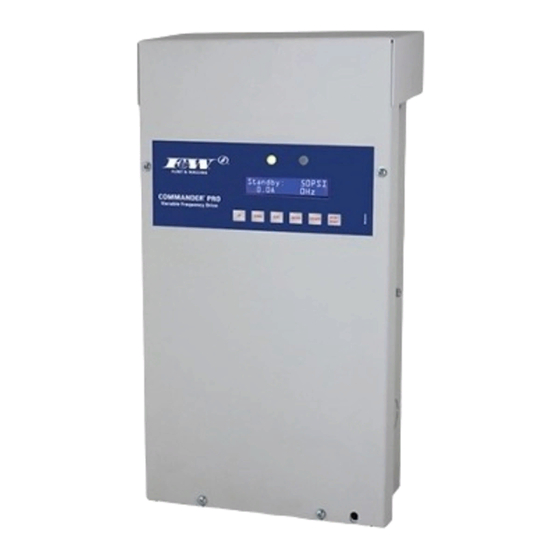
The Commander ® Pro Variable Speed Controller is a
dependable water system Variable Frequency Drive (VFD)
that uses custom programming to enhance the performance
of submersible pumps . When applied correctly to three phase
motor driven pumps, the drive eliminates pressure cycling
associated with conventional pressure switch controlled water
pumping systems and provides a constant output pressure .
Key features of the drive controller include:
•
Can use either a pressure switch (no snap action) or
a 4-20mA transducer as the pressure control . At initial
power up, the controller detects whether a switch or
transducer is connected and automatically sets the
control choice .
•
Constant water pressure with a wide range of settings
(30-80 psi) (Note: The maximum obtainable system
pressure is limited by the performance of the pump
installed)
•
Smaller pressure tank can be used
•
Fits the pump to the application – pump speed is
controlled to provide the optimum performance without
overloading the motor
•
No in-rush (power-on transient) current
•
Low motor start-up current (soft-starting)
•
Active Power Factor Correction minimizes input RMS
current
OWNER INFORMATION
System Model Number
Pump Model / Date Code
Pump Serial Number (Silver Label)
Motor Model / Date Code
Motor Serial Number (Silver Label)
Controller Model / Date Code
Dealer
Address
Install Date
Pro Variable
®
DESCRIPTIONS AND FEATURES
Flint & Walling © Copyright 2018. All rights reserved.
HELP LINE: 800-742-5044
•
Protection features
– Dry run conditions – using intelligent load monitoring
(see Page 7)
– Bound pump – with auto-reversing torque
– High voltage / lightning surge
– Low line voltage
– Short circuit
INCLUDED ITEMS:
A . Controller Unit
B . Pressure switch or Transducer
C . Switch or Transducer Cable
D . Installation Manual
E . Small Screwdriver
F .
Warranty Card
G . Switch Adjustment Tool (VS Systems only)
TABLE OF CONTENTS
Safety Instructions . . . . . . . . . . . . . . . . . . . . . . . . . . . . . . . . 2
System Components . . . . . . . . . . . . . . . . . . . . . . . . . . . . . . 3
Piping & General Information . . . . . . . . . . . . . . . . . . . . . . . 3
Controller Location Selection . . . . . . . . . . . . . . . . . . . . . . . 4
Controller Installation / Wiring . . . . . . . . . . . . . . . . . . . . . . . 5
Start-Up Operation . . . . . . . . . . . . . . . . . . . . . . . . . . . . . . . . 6
System Troubleshooting . . . . . . . . . . . . . . . . . . . . . . . . . . . 9
1
024983 F
Table of Contents
Troubleshooting

Summary of Contents for Flint & Walling Commander Pro
- Page 1 Commander Pro Variable ® Speed Controller System Instructions DESCRIPTIONS AND FEATURES The Commander ® Pro Variable Speed Controller is a • Protection features dependable water system Variable Frequency Drive (VFD) – Dry run conditions – using intelligent load monitoring that uses custom programming to enhance the performance (see Page 7) of submersible pumps .
- Page 2 IMPORTANT SAFETY INSTRUCTIONS Rules for safe installation and operation. Read these warnings and instructions carefully . Failure to follow them could cause serious bodily injury and/or property damage . Install all electrical equipment in protected area to Follow all local electrical and safety codes as well prevent mechanical damage which could produce serious as the National Electrical Code (NEC) and the electrical shock and/or equipment failure.
- Page 3 SYSTEM COMPONENTS PRESSURE SETTING GUIDE Please be sure that you have all major system components System Pressure Pressure Tank Setting necessary to properly install the submersible pump system . (at Pressure Sensor) (PSI) (+/- 2 psi) Other components may also be necessary depending on the application requirements .
- Page 4 . NOTICE: Regardless of owner’s manual, wire length should not exceed 1000 ft . If the Commander Pro Controller is used with above ground Pressure Notes do not print 6.8366...
- Page 5 Figure 3 Wire Illustration Green Ground wire (W) . Above Ground Motor (3-Phase Only): L1 to RED, NOTE: DO NOT USE ALUMINUM WIRE . L2 to BLK, L3 to YEL and Green Ground wire (W) ttention: To meet full compliance with FCC Part 15 Verify motor rotation to avoid damage Subpart B and CENELEC EN 55011, shielded motor to pump &...
- Page 6 "S2" on the display board terminal strip with a small c . Replace the rubber end cap . screwdriver (provided) . d . Reset the pressure tank pre-charge to the appropriate Tighten the strain relief on the pressure switch/transducer pressure lead .
- Page 7 Underload Sensitivity External alarm trip terminals The controller is configured at the factory to ensure detection The control is fitted with an Alarm In terminal block on the of Underload faults in a wide variety of pumping applications display board . Using these terminals, an external control including dead head and run dry conditions .
- Page 8 Note: If additional loads are being supplied by the generator, Minimum Generator rating the generator manufacture should be contacted for correct VS/TVS15 4 .8kW sizing . When the controller is being supplied power by a VS/TVS20 8 .0kW generator the Powered by Generator option should be set to YES in the advanced features menu to minimize possible VS/TVS30 10 .0kW...
- Page 9 Access menu options by pressing and holding edit and enter for 3 seconds . Menu Option Action Notes (2) Maximum motor current Set Max Motor Amps . Protects the pump motor assembly from operating beyond its Default 1 .5Hp Drive = 5 .9 A maximum capability .
- Page 10 Access menu options by pressing and holding edit and enter for 3 seconds . Menu Option Action Notes (8) Advanced features Drive parameters View the current output Hz, Amps & heat Used for diagnostic purposes in troubleshooting overheating drive . sink temperature .
- Page 11 SYSTEM TRIP CODE TROUBLESHOOTING Should an application or system problem occur, built-in diagnostics will protect the system . The red “FAULT” light on the front of the controller will flash and a fault condition will be shown on the display . In some cases, the system will shut itself off until corrective action has been taken .
- Page 12 SYSTEM TROUBLESHOOTING GUIDE SYMPTOM POSSIBLE CAUSE CORRECTIVE ACTION Water flow rate is not as Motor/Pump is running backwards . Switch two of the three wires leading from the controller to the high as expected . 3-phase motor . Pump capacity cannot supply the demand . Use pump with higher flow rating (if head requirement is still satisfied) .