Eaton 10C6 Mounting And Operating Instructions
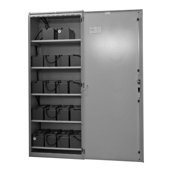
Ceag battery cabinets
Hide thumbs
Also See for 10C6:
- Installation instructions manual (12 pages) ,
- Installation instructions manual (20 pages)

Related Manuals for Eaton 10C6


Summary of Contents for Eaton 10C6
- Page 1 CEAG Battery Cabinets Mounting and Operating Instructions CEAG Battery Cabinets Target group, part 1: Qualified electricans acc. to DIN VDE 0105, part 1 Target group, part 2: Electrical instructed persons...
-
Page 2: Table Of Contents
3.4.5 With battery set 53.7 Ah ..35 Intended Use ....5 Compact-Battery Cabinets 10C6, 18C6, 26C6 . .36 Contents of Operating Instructions ..5 3.5.1 With battery set 23.3 Ah . - Page 3 Index Installation Safety Notes ....50 Battery Rooms, Ventilation and General Requirements ...50 6.2.1 Temperature ....50 6.2.2 Room Dimensions and Surface Conditions .
-
Page 4: General Information
1 General Information Important Notes 1.5 Copyright Protection All information from the contents, text, drawings, pictures 1 General Information and further representations are protected with regard to copy-right. 1.1 Description of Symbols 1.6 Spare Parts Important safety notes are marked with symbols in these Only use original spare parts from the manufacturer. -
Page 5: Intended Use
2 Safety • Never place tools on the batteries (metal tools are parti- Personnel without the necessary knowledge must be trained. cularly dangerous). • Check the starting torque of the block connector when 2.6 Operational Safety the bolted assembly is insecure (see Appendix). • Never lift the cells / monoblocs at the terminals. -
Page 6: Technical Data
3 Technical Data / Battery Installation 3 Technical Data / Battery Installation 3.1 Standard - Battery Cabinets 3.1.1 Standard - Battery Cabinet 23.3 Ah For interconnection see chapter „Circuit Diagrams“ Mounting and Operating Instructions CEAG Battery Cabinets 40071860035 (N) March 2016 www.ceag.de... -
Page 7: With Battery Set 32 Ah
3 Technical Data / Battery Installation 3.1.2 Standard-Battery Cabinet 32 Ah For interconnection see chapter „Circuit Diagrams“ Mounting and Operating Instructions CEAG Battery Cabinets 40071860035 (N) March 2016 www.ceag.de... -
Page 8: With Battery Set 39.8 Ah
3 Technical Data / Battery Installation 3.1.3 Standard-Battery Cabinet 39.8 Ah For interconnection see chapter „Circuit Diagrams“ Mounting and Operating Instructions CEAG Battery Cabinets 40071860035 (N) March 2016 www.ceag.de... -
Page 9: With Battery Set 50.4 Ah
3 Technical Data / Battery Installation 3.1.4 Standard-Battery Cabinet 50.4 Ah For interconnection see chapter „Circuit Diagrams“ Mounting and Operating Instructions CEAG Battery Cabinets 40071860035 (N) March 2016 www.ceag.de... -
Page 10: With Battery Set 53.7 Ah
3 Technical Data / Battery Installation 3.1.5 Standard-Battery Cabinet 53.7 Ah For interconnection see chapter „Circuit Diagrams“ Mounting and Operating Instructions CEAG Battery Cabinets 40071860035 (N) March 2016 www.ceag.de... -
Page 11: With Battery Set 66.2 Ah
3 Technical Data / Battery Installation 3.1.6 Standard-Battery Cabinet 66.2 Ah For interconnection see chapter „Circuit Diagrams“ Mounting and Operating Instructions CEAG Battery Cabinets 40071860035 (N) March 2016 www.ceag.de... -
Page 12: With Battery Set 85.7 Ah
3 Technical Data / Battery Installation 3.1.7 Standard-Battery Cabinet 85.7 Ah For interconnection see chapter „Circuit Diagrams“ Mounting and Operating Instructions CEAG Battery Cabinets 40071860035 (N) March 2016 www.ceag.de... -
Page 13: With Battery Set 89.4 Ah
3 Technical Data / Battery Installation 3.1.8 Standard-Battery Cabinet 89.4 Ah For interconnection see chapter „Circuit Diagrams“ Mounting and Operating Instructions CEAG Battery Cabinets 40071860035 (N) March 2016 www.ceag.de... -
Page 14: With Battery Set 106 Ah
3 Technical Data / Battery Installation 3.1.9 Standard-Battery Cabinet 106 Ah For interconnection see chapter „Circuit Diagrams“ Mounting and Operating Instructions CEAG Battery Cabinets 40071860035 (N) March 2016 www.ceag.de... -
Page 15: With Battery Set 118 Ah
3 Technical Data / Battery Installation 3.1.10 Standard-Battery Cabinet 118 Ah For interconnection see chapter „Circuit Diagrams“ Mounting and Operating Instructions CEAG Battery Cabinets 40071860035 (N) March 2016 www.ceag.de... -
Page 16: With Battery Set 143.1 Ah
3 Technical Data / Battery Installation 3.1.11 Standard-Battery Cabinet 143.1 Ah For interconnection see chapter „Circuit Diagrams“ Mounting and Operating Instructions CEAG Battery Cabinets 40071860035 (N) March 2016 www.ceag.de... -
Page 17: With Battery Set 155.6 Ah
3 Technical Data / Battery Installation 3.1.12 Standard-Battery Cabinet 155.6 Ah For interconnection see chapter „Circuit Diagrams“ Mounting and Operating Instructions CEAG Battery Cabinets 40071860035 (N) March 2016 www.ceag.de... -
Page 18: With Battery Set 178.8 Ah
3 Technical Data / Battery Installation 3.1.13 Standard-Battery Cabinet 178.8 Ah For interconnection see chapter „Circuit Diagrams“ Mounting and Operating Instructions CEAG Battery Cabinets 40071860035 (N) March 2016 www.ceag.de... -
Page 19: With Battery Set 195.4 Ah
3 Technical Data / Battery Installation 3.1.14 Standard-Battery Cabinet 195.4 Ah For interconnection see chapter „Circuit Diagrams“ Mounting and Operating Instructions CEAG Battery Cabinets 40071860035 (N) March 2016 www.ceag.de... -
Page 20: With Battery Set 245 Ah
3 Technical Data / Battery Installation 3.1.15 Standard-Battery Cabinet 245 Ah For interconnection see chapter „Circuit Diagrams“ Mounting and Operating Instructions CEAG Battery Cabinets 40071860035 (N) March 2016 www.ceag.de... -
Page 21: With Battery Set 268.2 Ah
3 Technical Data / Battery Installation 3.1.16 Standard-Battery Cabinet 268.2 Ah For interconnection see chapter „Circuit Diagrams“ Mounting and Operating Instructions CEAG Battery Cabinets 40071860035 (N) March 2016 www.ceag.de... -
Page 22: With Battery Set 308 Ah
3 Technical Data / Battery Installation 3.1.17 Standard-Battery Cabinet 308 Ah For interconnection see chapter „Circuit Diagrams“ Mounting and Operating Instructions CEAG Battery Cabinets 40071860035 (N) March 2016 www.ceag.de... -
Page 23: With Battery Set 357 .6 Ah
3 Technical Data / Battery Installation 3.1.18 Standard-Battery Cabinet 357.6 Ah For interconnection see chapter „Circuit Diagrams“ Mounting and Operating Instructions CEAG Battery Cabinets 40071860035 (N) March 2016 www.ceag.de... -
Page 24: Compact-Battery Cabinets 2C3
3 Technical Data / Battery Installation 3.2 Compact-Battery Cabinets 2C3 3.2.1 With battery set 5.5 Ah For interconnection see chapter „Circuit Diagrams“ Mounting and Operating Instructions CEAG Battery Cabinets 40071860035 (N) March 2016 www.ceag.de... -
Page 25: With Battery Set 8.5 Ah
3 Technical Data / Battery Installation 3.2.2 With battery set 8.5 Ah For interconnection see chapter „Circuit Diagrams“ Mounting and Operating Instructions CEAG Battery Cabinets 40071860035 (N) March 2016 www.ceag.de... -
Page 26: With Battery Set 14 Ah
3 Technical Data / Battery Installation 3.2.3 With battery set 14 Ah For interconnection see chapter „Circuit Diagrams“ Mounting and Operating Instructions CEAG Battery Cabinets 40071860035 (N) March 2016 www.ceag.de... -
Page 27: Compact-Battery Cabinets 10C3, 18C3
3 Technical Data / Battery Installation 3.3 Compact-Battery Cabinets 10C3, 18C3 3.3.1 With battery set 5.5 Ah For interconnection see chapter „Circuit Diagrams“ Mounting and Operating Instructions CEAG Battery Cabinets 40071860035 (N) March 2016 www.ceag.de... -
Page 28: With Battery Set 8.5 Ah
3 Technical Data / Battery Installation 3.3.2 With battery set 8.5 Ah For interconnection see chapter „Circuit Diagrams“ Mounting and Operating Instructions CEAG Battery Cabinets 40071860035 (N) March 2016 www.ceag.de... -
Page 29: With Battery Set 14 Ah
3 Technical Data / Battery Installation 3.3.3 With battery set 14 Ah For interconnection see chapter „Circuit Diagrams“ Mounting and Operating Instructions CEAG Battery Cabinets 40071860035 (N) March 2016 www.ceag.de... -
Page 30: With Battery Set 23.3 Ah
3 Technical Data / Battery Installation 3.3.4 With battery set 23.3 Ah For interconnection see chapter „Circuit Diagrams“ Mounting and Operating Instructions CEAG Battery Cabinets 40071860035 (N) March 2016 www.ceag.de... -
Page 31: Compact-Battery Cabinets 10C
3 Technical Data / Battery Installation 3.4 Compact-Battery Cabinets 10C 3.4.1 With battery set 23.3 Ah For interconnection see chapter „Circuit Diagrams“ Mounting and Operating Instructions CEAG Battery Cabinets 40071860035 (N) March 2016 www.ceag.de... -
Page 32: With Battery Set 32 Ah
3 Technical Data / Battery Installation 3.4.2 With battery set 32 Ah For interconnection see chapter „Circuit Diagrams“ Mounting and Operating Instructions CEAG Battery Cabinets 40071860035 (N) March 2016 www.ceag.de... -
Page 33: With Battery Set 39.8 Ah
3 Technical Data / Battery Installation 3.4.3 With battery set 39.8 Ah For interconnection see chapter „Circuit Diagrams“ Mounting and Operating Instructions CEAG Battery Cabinets 40071860035 (N) March 2016 www.ceag.de... -
Page 34: With Battery Set 50.4 Ah
3 Technical Data / Battery Installation 3.4.4 With battery set 50.4 Ah For interconnection see chapter „Circuit Diagrams“ Mounting and Operating Instructions CEAG Battery Cabinets 40071860035 (N) March 2016 www.ceag.de... -
Page 35: With Battery Set 53.7 Ah
3 Technical Data / Battery Installation 3.4.5 With battery set 53.7 Ah For interconnection see chapter „Circuit Diagrams“ Mounting and Operating Instructions CEAG Battery Cabinets 40071860035 (N) March 2016 www.ceag.de... -
Page 36: Compact-Battery Cabinets 10C6, 18C6, 26C6
3 Technical Data / Battery Installation 3.5 Compact-Battery Cabinets 10C6, 18C6, 26C6 3.5.1 With battery set 23.3 Ah For interconnection see chapter „Circuit Diagrams“ Mounting and Operating Instructions CEAG Battery Cabinets 40071860035 (N) March 2016 www.ceag.de... -
Page 37: With Battery Set 32.0 Ah
3 Technical Data / Battery Installation 3.5.2 With battery set 32 Ah For interconnection see chapter „Circuit Diagrams“ Mounting and Operating Instructions CEAG Battery Cabinets 40071860035 (N) March 2016 www.ceag.de... -
Page 38: With Battery Set 39.8 Ah
3 Technical Data / Battery Installation 3.5.3 With battery set 39.8 Ah For interconnection see chapter „Circuit Diagrams“ Mounting and Operating Instructions CEAG Battery Cabinets 40071860035 (N) March 2016 www.ceag.de... -
Page 39: With Battery Set 50.4 Ah
3 Technical Data / Battery Installation 3.5.4 With battery set 50.4 Ah For interconnection see chapter „Circuit Diagrams“ Mounting and Operating Instructions CEAG Battery Cabinets 40071860035 (N) March 2016 www.ceag.de... -
Page 40: With Battery Set 53.7 Ah
3 Technical Data / Battery Installation 3.5.5 With battery set 53.7 Ah For interconnection see chapter „Circuit Diagrams“ Mounting and Operating Instructions CEAG Battery Cabinets 40071860035 (N) March 2016 www.ceag.de... -
Page 41: With Battery Set 66.2 Ah
3 Technical Data / Battery Installation 3.5.6 With battery set 66.2 Ah For interconnection see chapter „Circuit Diagrams“ Mounting and Operating Instructions CEAG Battery Cabinets 40071860035 (N) March 2016 www.ceag.de... -
Page 42: With Battery Set 85.7 Ah
3 Technical Data / Battery Installation 3.5.7 With battery set 85.7 Ah For interconnection see chapter „Circuit Diagrams“ Mounting and Operating Instructions CEAG Battery Cabinets 40071860035 (N) March 2016 www.ceag.de... -
Page 43: With Battery Set 89.4 Ah
3 Technical Data / Battery Installation 3.5.8 With battery set 89.4 Ah For interconnection see chapter „Circuit Diagrams“ Mounting and Operating Instructions CEAG Battery Cabinets 40071860035 (N) March 2016 www.ceag.de... -
Page 44: Circuit Diagram
4 Circuit Diagrams 4 Circuit Diagrams 4.1 Wiring 5.5 Ah to 89.4 Ah 4.2 Wiring 118 Ah IMPORTANT NOTE! Only one temperature sensor per charger has to be installed. A series- or parallel connection of the temperature sensor can cause an improper charging of the battery. Mounting and Operating Instructions CEAG Battery Cabinets 40071860035 (N) March 2016 www.ceag.de... -
Page 45: Wiring 106, 143.1, 155.6, 178.8 Ah
4 Circuit Diagrams 4.3 Wiring 106 Ah, 143.1 Ah, 155.6 Ah, 178.8 Ah PE-conductor rail - conductor rail + conductor rail Battery Distribution Panel see separate installation instruction 30080001443 IMPORTANT NOTE! Only one temperature sensor per charger has to be installed. A series- or parallel connection of the temperature sensor can cause an improper charging of the battery. -
Page 46: Wiring 195.4, 245, 268.2 Ah
4 Circuit Diagrams 4.4 Wiring 195.4 Ah, 245 Ah, 268.2 Ah PE-conductor rail - conductor rail + conductor rail Battery Distribution Panel see separate installation instruction 30080001443 IMPORTANT NOTE! Only one temperature sensor per charger has to be installed. A series- or parallel connection of the temperature sensor can cause an improper charging of the battery. -
Page 47: Wiring 308, 357 .6 Ah
4 Circuit Diagrams 4.5 Wiring 308 Ah, 357.6 Ah Battery Distribution Panel see separate installation instruction 30080001443 IMPORTANT NOTE! Only one temperature sensor per charger has to be installed. A series- or parallel connection of the temperature sensor can cause an improper charging of the battery. PE-conductor rail - conductor rail + conductor rail... -
Page 48: Transport, Packaging And Storage
5 Transport, Packaging and Storage 5 Transport, Packaging and Storage IMDG: The International Maritime Dangerous Goods Code IATA: The International Air Transportation Association (world- wide) 5.1 Safety Notes ICAO: Civil Aviation Organization’s Technical Instructions for the Safe Transport of Dangerous Goods by Air WARNING! RISK OF INJURY! 5.6 Transport Inspection Check delivery on receipt for completeness and for transport... -
Page 49: Storage
5 Transport, Packaging and Storage • Avoid storing unpacked cells / monoblocs on sharp- 5.12 Measures during Storage edged supports. Appropriate inventory turnover based on FIFO - method (“First In- First Out”) will result in a higher operating quality • It is recommended to have the same storage conditions of the products. -
Page 50: Installation
6 Installation 6 Installation 6.1 Safety Notes WARNING! RISK OF INJURY! Improper mounting and installation can cause serious per- sonal injury and / or material damage. This work must only be performed by authorised, skilled and adequate personnel who have received instructions providing information on the device and in observance of the local safety regulations. -
Page 51: Room Dimensions And Surface Conditions
6 Installation 6.2.2 Room dimensions and Surface conditions Floors shall be reasonably level and able to support the battery weight. From EN 50272-2: “ ...The floor area for a person standing within arm´s reach of the battery shall be electrostatic dissi- pative in order to prevent electrostatic charge generation. -
Page 52: Ventilation Requirements
6 Installation 6.2.3.1 Ventilation requirements 6.2.3.2 Close vicinity of the battery From EN 50272-2: “ …In the close vicinity of the battery the Ventilation of electrical rooms dilution of explosive gases is not always secured. Therefore Dimensions of ventilation acc. to EN 50272-2. a safety distance extending through air must be observed The minimum air flow rate for ventilation of a battery location within which sparking or glowing devices (max. -
Page 53: Preparations
6 Installation 6.3 Preparations • The minimum cable size for the end connectors of a string is 25 mm/100 Ah string capacity. Check each cell/ monobloc separately by measuring the • The end-connector cables must be placed on a copper open circuit voltage. -
Page 54: Commissioning
7 Commissioning 7 Commissioning • the storage conditions, • the cleanliness of the battery and equipment • and other conditions relevant to safety issues and battery´s Further information about operating can be found in the service life (battery room ventilation, for example). operating instructions for ZB-S, No. -
Page 55: Failures
10 Failures 10 Failures 10.1 Reaction to Failure Further information about failures can be found in the ope- rating instructions for ZB-S, No. 40071860179. 11 Spare parts Only use original spare parts from the manufacturer. ATTENTION! Wrong or faulty spare parts from other manufacturers can cause serious damage to the battery. -
Page 56: Appendix
7 Commissioning A D ivisio n o E f xide T echnologies echnologies Operating Instruction Stationary valve regulated lead-acid batteries 81700849 Nominal data • Nominal voltage U : 2.0V x number of cells • Nominal capacity C : 10 h; 20 h discharge (see type plate on cells/blocks and technical data in these instructions) •... - Page 57 d.) Battery operation (charge-/discharge Float voltage Nominal Charging current operation) [Vpc] temp. [° C] Marathon L/XL 10 to 35 A per 100Ah The load is only supplied by the battery. The 7 Commissioning Marathon L/XL 2.27 Marathon M/M-FT 10 to 35 A per 100Ah charging process depends on the application Marathon M/M-FT 2.27...
- Page 58 2.45 7 Commissioning 2.40 2.35 Float 2.30 2.25 2.20 2.15 Temperature [°C] Fig. 2: Marathon M/M-FT, Sprinter P/XP, Sprinter S; charging voltage vs. temperature 2.9 Electrolyte If the cell or block voltage differ from the average 4. T e sts The electrolyte is diluted sulphuric acid and fixed float charge voltage by more than the values T e sts have to be carried out according to...
- Page 59 Mounting and Operating Instructions CEAG Battery Cabinets 40071860035 (N) March 2016 www.ceag.de...
- Page 60 The aim of Eaton is to provide a reliable, efficient and safe power supply where it is needed most. Eaton's experts have comprehensive in-depth specialist knowledge in the area of energy management in the most diverse of sectors and therefore they are able to provide customer-specific, inte- grated solutions to meet the most challenging demands of its customers.