Table of Contents
I.L. 70C1037H04
Instructions for Digitrip Models 220+, and 520, 520i and
520M, 520Mi, and 520MC, 520MCi Trip Units for use only in
Cutler-Hammer Magnum and Magnum DS Circuit Breakers
Table of Contents
1.0 General Description of Digitrip Trip Units ................. 2
1.1 Protection ............................................................... 5
1.2 Mode of Trip and Status Information ........................ 5
1.3 Installation and Removal .......................................... 5
1.3.1 Installation of the Trip Unit ............................ 5
1.3.2 Rating Plug Installation ................................ 5
1.3.3 Trip Unit/Rating Plug Removal ...................... 6
1.4 Wiring ..................................................................... 7
1.5 Plexiglass Cover ..................................................... 7
(520M & 520MC Models only) ................................. 7
1.6.1 Auxiliary Power ............................................ 7
1.6.2 Ground Alarm ............................................... 7
1.6.3 Ground Fault Trip ......................................... 7
1.6.4 Ground Fault Alarm ...................................... 7
1.6.5 High Load Alarm ......................................... 7
1.7 Display Feature (520M and 520MC only) ................. 8
1.8 Standards ................................................................ 8
Magnum Circuit Breakers ........................................ 8
2.1 General ................................................................... 8
2.2 Low Energy Trip Actuator ........................................ 9
2.3 Ground Fault Protection .......................................... 9
2.3.1 General ...................................................... 10
2.3.2 Residual Sensing ....................................... 10
2.3.3 Source Ground Sensing ............................. 10
2.3.4 Zero Sequence Sensing ............................. 10
2.3.5 Multiple Source/Multiple Ground ................ 10
2.3.6 Ground Fault Settings ................................ 11
or equal to 3200A) ................................................. 11
than 3200A) .......................................................... 11
3.0 Principles of Operation .......................................... 11
3.1 General ................................................................. 11
3.2 Trip and Operation Indicators ................................. 16
3.3 Making Current Release ........................................ 16
3.4 Zone Interlocking (520 family only) ........................ 16
4.0 Protection Settings ............................................... 21
4.1 General ................................................................. 21
4.2 Long Delay Current Setting ................................... 21
4.3 Long Delay Time Setting ....................................... 22
4.4 Short Delay Current Setting ................................... 22
4.5 Short Delay Time Setting ...................................... 22
4.6 Instantaneous Current Setting ............................... 22
4.7 Ground Fault Current Setting ................................. 23
4.8 Ground Fault Time Delay Setting .......................... 23
4.9 INCOM Communications (520MC model only) ....... 23
4.9.1 Breaker Interface Module (BIM) .................. 23
4.9.2 Remote Master Computer .......................... 24
4.9.3 INCOM Network Interconnections ............... 24
Effective 7/1/2003
Courtesy of NationalSwitchgear.com
5.0 Test Procedures .................................................... 25
5.1 General ................................................................. 25
5.2 When to Test ........................................................ 25
5.3 Functional Field Testing ........................................ 25
5.3.1 Field Test Kit ............................................... 25
5.3.2 Handheld Functional Test Kit ...................... 25
5.3.2.1 Description of Handheld Test Kit ...... 26
5.3.2.2 Test Procedure ................................ 26
5.3.2.3 Currents .......................................... 26
5.3.2.4 Batteries ......................................... 26
Trip Units - Primary Injection ................................. 27
5.4.1 Code Requirements ................................... 27
5.4.2 Standards Requirements ............................ 27
5.4.3 General Test Instructions ........................... 27
6.0 Battery ................................................................. 28
6.1 General ................................................................. 28
6.2 Battery Check ....................................................... 28
6.3 Battery Installation and Removal ........................... 28
(Current Sensor Ratings and Rating Plugs) ..... 11, 28
8.0 Record Keeping .................................................... 29
9.0 References ............................................................ 29
9.1 Magnum and Magnum DS Circuit Breakers ........... 29
9.2 Time-Current Curves .............................................. 29
Appendix A Zone Interlocking Examples ...................... 33
Appendix B Troubleshooting Guide .............................. 35
Appendix D Modbus Translator Wiring ......................... 38
WARNING
DO NOT ATTEMPT TO INSTALL OR PERFORM
MAINTENANCE ON EQUIPMENT WHILE IT IS
ENERGIZED. DEATH OR SEVERE PERSONAL INJURY
CAN RESULT FROM CONTACT WITH ENERGIZED
EQUIPMENT. ALWAYS VERIFY THAT NO VOLTAGE IS
PRESENT BEFORE PROCEEDING. ALWAYS FOLLOW
SAFETY PROCEDURES. CUTLER-HAMMER IS NOT
LIABLE FOR THE MISAPPLICATION OR
MISINSTALLATION OF ITS PRODUCTS.
WARNING
OBSERVE ALL RECOMMENDATIONS, NOTES, CAU-
TIONS, AND WARNINGS RELATING TO THE SAFETY
OF PERSONNEL AND EQUIPMENT. OBSERVE AND
COMPLY WITH ALL GENERAL AND LOCAL HEALTH
AND SAFETY LAWS, CODES, AND PROCEDURES.
I.L. 70C1037H04
Page 1
Table of Contents

Related Manuals for Eaton Cutler-Hammer Magnum Digitrip 220+


Summary of Contents for Eaton Cutler-Hammer Magnum Digitrip 220+
-
Page 1: Table Of Contents
I.L. 70C1037H04 I.L. 70C1037H04 Page 1 Instructions for Digitrip Models 220+, and 520, 520i and 520M, 520Mi, and 520MC, 520MCi Trip Units for use only in Cutler-Hammer Magnum and Magnum DS Circuit Breakers Table of Contents 5.0 Test Procedures ............ 25 5.1 General .............. -
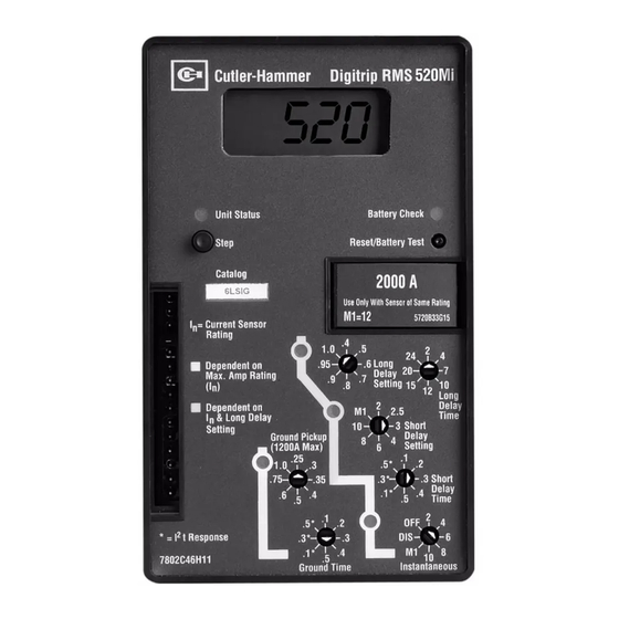
Page 2: General Description Of Digitrip Trip Units
I.L. 70C1037H04 Page 2 Figure 1.1 Digitrip 520MC Trip Unit with Rating Plug NOTE: The recommendations and information contained This instruction book specifically covers the application of herein are based on experience and judgement, but should Digitrip Trip Units (see Figure 1.1) installed in Magnum and not be considered to be all inclusive or to cover every Magnum DS Breakers. - Page 3 I.L. 70C1037H04 Page 3 Table 1.1a Protection Types Available for Digitrip Trip Units Digitrip Trip Unit Type 520/520i 520M/520Mi 520MC/520MCi Ampere Range 100A-3200A 100A-6300A 100A-6300A 100A-6300A RMS Sensing Communications Protection and Coordination Figure Number Reference 3.2.1 3.2.2, 3.2.3, 3.2.4 3.3.1, 3.3.3, 3.3.2, 3.3.4 3.4.1, 3.4.3, 3.4.2, 3.4.4 Protection Ordering Options...
- Page 4 I.L. 70C1037H04 Page 4 Table 1.1b Communication Functions Available for Digitrip 520MC Units Catalog Number 5CLSI 5CLSIG 5CLSIA 5WLSIG REMOTE INFORMATION VIA COMMUNICATIONS Breaker Status OPEN/CLOSED/TRIPPED Address register Trip Event Values: Protection Settings Current Values Phase A Current (amperes) Phase B Current (amperes) Phase C Current (amperes) Phase N Current (amperes) Phase G Current (amperes)
-
Page 5: Protection
I.L. 70C1037H04 Page 5 1.2 Mode of Trip and Status Information All trip unit models are microprocessor-based ac protec- tion devices that provide true RMS current sensing for the On all models, a green light emitting diode (LED), labeled proper coordination with the thermal characteristics of Status, blinks approximately once each second to indicate conductors and equipment. -
Page 6: Trip Unit/Rating Plug Removal
I.L. 70C1037H04 Page 6 Mounting Boss J3 (3 Point) Steel Mounting Plate J4 (4 Point) Guide Pin Connectors Digitrip 220/520 Dimple Pin 1 Ground Alarm/Power Connector K2 Supply Module (520M/MC option only) M-4 x 80mm Mounting Screw Rating Plug (3 Pins) Pin 1 Connector K1 0.045 Dia. -
Page 7: Wiring
I.L. 70C1037H04 Page 7 1.4 Wiring The internal components of the breaker, and how they are wired out to the breaker secondary contacts, are shown in the breaker master connection diagram provided as Appendix C. 1.5 Plexiglass Cover A clear, tamper-proof, plexiglass door sits on the breaker cover. -
Page 8: Display Feature (520M And 520Mc Only)
I.L. 70C1037H04 Page 8 Pushing the Step button while the unit is in the OL mode will have the unit again display the overload Ground Ground current value. Fault Trip Fault Alarm Remote HighLoad Alarm (Cat 5MLSI and 5CLSI only) Control Voltage HELP This message can indicate more than one problem... -
Page 9: Low Energy Trip Actuator
I.L. 70C1037H04 Page 9 3. The low-energy Trip Actuator, which actually trips the OBSERVE POLARITY MARKINGS ON THE TRIP AC- circuit breaker TUATOR LEADS AND CONNECT THEM PROPERLY, USING THE INSTRUCTIONS PROVIDED. Figure 2.1 shows this tripping circuit for a typical Magnum 2.2 Low-Energy Trip Actuator Breaker. -
Page 10: General
I.L. 70C1037H04 Page 10 2.3.1 General CAUTION When the Digitrip 520 family includes ground fault protec- tion features, the distribution system characteristics (for IF THE SENSOR CONNECTIONS ARE INCORRECT, A example, system grounding, number of sources, number NUISANCE TRIP MAY OCCUR. ALWAYS OBSERVE THE and location of ground points, and the like) must be POLARITY MARKINGS ON THE INSTALLATION DRAW- considered along with the manner and location in which... -
Page 11: Ground Fault Settings
3780 4725 6300 The Digitrip uses the Eaton custom-designed CHip™ 1. Tolerance on settings are ±10% of values shown. (Cutler Hammer Integrated Processor) chip, an integrated 2. On Models 520 LSIG, 520M and 520MC LSIG, the shaded values are set to a circuit that includes a microcomputer to perform its maximum trip value of 1200 amperes for NEC. - Page 12 I.L. 70C1037H04 Page 12 Source Black K1-2 Trip Digitrip 520 Actuator K1-3 with GF 10:1 K1-9 K1-8 K1-7 K1-6 K1-5 K1-4 K2-1 K2-7 K2-9 K2-8 10:1 AUX. CT Load Notes: In this scheme, all breaker secondary currents (at the 100 mA level) are summed together at the PC board donut transformer to sense ground fault via element R 5 .
- Page 13 I.L. 70C1037H04 Page 13 Figure 2.4 Digitrip Neutral Sensor Types Source Black K1-2 Trip Digitrip 520 Actuator K1-3 with GF 10:1 K1-9 K1-8 K1-7 K1-6 K1-5 K1-4 K2-9 K2-8 10:1 AUX. CT Load Notes: In this scheme, all breaker secondary currents (at the 100 mA level) are summed together at the PC board donut transformer to sense ground fault via element R Do not jumper on secondary contacts B-6, B-7.
- Page 14 I.L. 70C1037H04 Page 14 Figure 2.6 Source Ground Fault Sensing Scheme for 3200A Frame Figure 2.7 Source Ground Fault Sensing Scheme for 4000A Frame Effective 7/1/2003 Courtesy of NationalSwitchgear.com...
- Page 15 I.L. 70C1037H04 Page 15 Figure 2.8 Zero Sequence Sensing Scheme for 3200A Frame I /2 φ φ I /2 I /2 I /2 i /2 i /2 i /2 Digitrip Ground Sensor i /2 i /2 Neutral Sensors Wired in a Loop Configuration Notes: Breaker M2 trips since this is the only breaker seeing the I fault via element R .
-
Page 16: Trip And Operation Indicators
I.L. 70C1037H04 Page 16 3.2 Trip and Operation Indicators 3.4 Zone Interlocking (520 family only) The LEDs on the face of the trip unit, shown in Figures 1.1 CAUTION and 3.2 to 3.4, flash red to indicate the reason for any automatic trip operation. - Page 17 I.L. 70C1037H04 Page 17 Effective 7/1/2003 Courtesy of NationalSwitchgear.com...
- Page 18 I.L. 70C1037H04 Page 18 Figure 3.2.2 Digitrip 520 LSI Figure 3.2.1 Digitrip 220 PLI Figure 3.2.3 Digitrip 520 LSIG Figure 3.2.4 Digitrip 520i WLSIG Effective 7/1/2003 Courtesy of NationalSwitchgear.com...
- Page 19 I.L. 70C1037H04 Page 19 Figure 3.3.1 Digitrip 520M MLSI Figure 3.3.2 Digitrip 520M MLSIA Figure 3.3.3 Digitrip 520M MLSIG Figure 3.3.4 Digitrip 520Mi MWLSIG Effective 7/1/2003 Courtesy of NationalSwitchgear.com...
- Page 20 I.L. 70C1037H04 Page 20 Figure 3.4.2 Digitrip 520MC CLSIA Figure 3.4.1 Digitrip 520MC CLSI Figure 3.4.4 Digitrip 520MC CWLSIG Figure 3.4.3 Digitrip 520MC CLSIG Effective 7/1/2003 Courtesy of NationalSwitchgear.com...
-
Page 21: Protection Settings
I.L. 70C1037H04 Page 21 4.0 PROTECTION SETTINGS 4.3 Long Delay Time Setting 4.1 General There are 8 available Long Delay Time Settings, as illustrated in Figure 4.2, ranging from 2 to 24 seconds. Before placing any circuit breaker in operation, set each These settings are the total clearing times when the trip unit protection setting to the values specified by the current value equals 6 times (Ir). -
Page 22: Long Delay Time Setting
I.L. 70C1037H04 Page 22 Digitrip Test Kit Port Test Test Connector (Storage) “LTM Active ” Notch Connector (Bridging) “LTM Inactive ” (Also Recommended Position for Field Testing) Figure 4.3 Long Time Memory (LTM) Jumper The action of the LTM must be considered when performing multiple Long Delay Time tests (See Section 5.4). -
Page 23: Ground Fault Current Setting
I.L. 70C1037H04 Page 23 Available Settings Setting Inst. Gnd. Fault Time 2, 3, 4, 6, 8, x n I Sec. 10, M1, OFF* In Multiples of Rating Plug Amperes ( n) Available Settings M1 value is specified on rating plug. .1, .2, .3, .4, .5 *No OFF on Digitrip 220. -
Page 24: Remote Master Computer
I.L. 70C1037H04 Page 24 Typical IBM Compatible Computer Breaker Interface Monitor (BIM) See View A Twisted Pair. No. 18 AWG. Cut-off Shield or connect to C-H Coni. Card unused customer terminal -- Do not Ground. 0 0 2 0 0 1 H = 9600 Baud (BL) Typical Magnum... -
Page 25: Test Procedures
I.L. 70C1037H04 Page 25 5.3 Functional Field Testing 5.0 TEST PROCEDURES CAUTION 5.1 General PERFORMING TESTS WITHOUT THE CUTLER-HAM- WARNING MER-APPROVED TEST KIT MAY DAMAGE THE DIG- ITRIP UNIT. DO NOT ATTEMPT TO INSTALL, TEST, OR PERFORM 5.3.1 Field Test Kit MAINTENANCE ON EQUIPMENT WHILE IT IS ENER- GIZED. -
Page 26: Description Of Handheld Test Kit
I.L. 70C1037H04 Page 26 Delay Setting will affect the per unit (Ir) current value and 5.3.2 Functional Test Kit (handheld) the response of the Digitrip unit. 5.3.2.1 Description of Handheld Test Kit 5.3.2.4 Batteries A battery powered test kit is also available and capable of testing trip elements for Digitrip units 520/520M/520MC The Functional Test Kit contains a total of seven 9-Volt and Digitrip 220+, including power up, Instantaneous Trip,... -
Page 27: Performance Testing For Ground Fault Trip Units - Primary Injection
I.L. 70C1037H04 Page 27 WARNING PERSONAL INJURY CAN OCCUR WHEN WORKING ON POWER SYSTEMS. ALWAYS TURN OFF POWER SUPPLYING BREAKER BEFORE CONDUCTING TESTS. TEST OUT OF THE CELL, IF POSSIBLE. THERE IS A HAZARD OF ELECTRICAL SHOCK OR BURN WHEN- EVER WORKING IN OR AROUND ELECTRICAL EQUIP- MENT. -
Page 28: Battery
I.L. 70C1037H04 Page 28 Insulating Tab 6.0 TRIP UNIT BATTERY Rating Plug door flipped open 6.1 General The battery plays no part in the protection function of the USE TYPE trip unit. 1/3 N LITHIUM BATTERY ONLY As indicated in Figure 3.1, the battery is provided to Pull to Remove Battery maintain the red LED indication of the Cause of Trip. -
Page 29: Frame Ratings
I.L. 70C1037H04 Page 29 7.0 FRAME RATINGS (SENSOR RATINGS AND RATING PLUGS) interior of the breaker cell door or another visible location. Figure 8.3 provides a place for recording test data and The frame rating of a circuit breaker is the maximum RMS actual trip values. - Page 30 I.L. 70C1037H04 Page 30 DIGITRIP TRIP FUNCTION SETTINGS Circuit No./Address Breaker Shop Order Reference PER UNIT MULTIPLIERS Rating Plug Amperes Ir Continuous Ampere Rating (In) = LDS x In Ampere Trip Per Unit Equivalent Function Setting Multi Setting Time Delay Inst.
- Page 31 I.L. 70C1037H04 Page 31 DIGITRIP AUTOMATIC TRIP OPERATION RECORD Circuit No./Address Breaker Shop Order Reference Trip Function Settings Reference Orig. 0 Rev. 1 Rev. 2 Rev. 3 Instantaneous Long Delay Setting Long Delay Time Short Setting Short Time Ground Fault Setting Ground Fault Time Setting Date...
- Page 32 I.L. 70C1037H04 Page 32 GROUND FAULT TEST RECORD FORM Ground Fault Test Record should be retained by those in charge of the building's electrical installation in order to be available to the authority having jurisdiction. Test Date Circuit Breaker Results Tested by Number Figure 8.3 Typical Performance Test Record Form...
-
Page 33: Appendix A Zone Interlocking Examples
I.L. 70C1037H04 Page 33 Fault at location 2 NOTICE The feeder breaker trip unit will initiate the trip in 0.045 seconds to clear the fault and will send an interlock- ing signal to the main trip unit. The main trip unit will begin THE PROVISION FOR ZONE INTERLOCKING IS STAN- to time out and, in the event that the feeder breaker Z2 DARD ON MAGNUM CIRCUIT BREAKERS WITH DIG-... - Page 34 I.L. 70C1037H04 Page 34 Notes: Wiring to be twisted pair of AWG #14 to #20. Route 3200A Main Zone Interlocking wiring separate from power conductors. DO NOT GROUND any Zone Interlocking wiring. Zone 0.5 Sec The maximum distance between two farthest breakers 1200A on different zones (from the ZO downstream to ZI upstream terminals) is 250 feet (76m).
-
Page 35: Appendix B Troubleshooting Guide
I.L. 70C1037H04 Page 35 Appendix B Troubleshooting Guide Symptom Probable Cause Possible Solution(s) References Unit status LED is not Current through breaker is No problem. Status LED will blinking. <25% of sensor rating. not operate with breaker currents <25% of sensor rating. - Page 36 I.L. 70C1037H04 Page 36 Symptom Probable Cause Possible Solution(s) References Cause of Trip LEDs flashing Trip Unit was not reset from Depress Reset Pushbutton to and breaker is closed previous event or test. clear LED flashing Battery voltage too low to Replace battery See Section 6.2 reset latch chip and LEDs...
-
Page 37: Appendix C Typical Breaker Master Conn. Diagram
I.L. 70C1037H04 Page 37 Appendix C Typical Breaker Master Connection Diagram Effective 7/1/2003 Courtesy of NationalSwitchgear.com... -
Page 38: Appendix D Modbus Translator Wiring
I.L. 70C1037H04 Page 38 Appendix D MODBUS TRANSLATOR Wiring The Digitrip 520MC in a Magnum Breaker can communicate its data using Modbus RTU protocol by employing a mMINT device to act as a translator from INCOM communicationto MODBUS communications. A Modbus master device is shown wired to gather data. The mMINT module CAT # MMINT use DIN rail mounting. - Page 39 I.L. 70C1037H04 Page 39 This instruction booklet is published solely for information purposes and should not be considered all inclusive. If further information is required, consult Cutler-Hammer, Inc. The sale of the product shown in this literature is subject to the terms and conditions outlined in appropriate Cutler- Hammer, Inc., selling policies or other contractual agree- ments between the parties.
- Page 40 I.L. 70C1037H04 Page 40 Cutler-Hammer Pittsburgh, PA U.S.A. Effective 7/1/2003 Printed in U.S.A. Effective 7/1/2003 Courtesy of NationalSwitchgear.com...