
Related Manuals for Emerson THUM

Summary of Contents for Emerson THUM
- Page 1 Quick Start Guide 00825-0100-4075, Rev GE September 2020 ™ Emerson Wireless THUM Adapter...
-
Page 2: Table Of Contents
Emerson.com/Rosemount. Equipment Damage During normal operation, or in fault condition, the THUM Adapter will cause a 2.5 V drop in the connected loop. It is important to ensure that the power supply can provide at least 2.5 V more than the minimum operating voltage of the wired device to make sure it works properly with the THUM Adapter installed. - Page 3 September 2020 Quick Start Guide AMS Device Manager......................... 28 Field Communicator........................29 Perform loop current test......................30 Verify operation......................... 32 Troubleshooting........................34 Reference information....................... 35 Product Certifications.........................36 Quick Start Guide...
- Page 4 Quick Start Guide September 2020 Emerson.com/Rosemount...
-
Page 5: Wireless Considerations
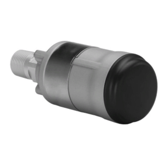
Figure 1-1: THUM Adapter Position Conduit entry When installing the THUM Adapter into the conduit entry of a wired device, use an approved thread sealant. Thread sealant provides a water tight seal. The thread sealant also provides lubrication to ensure easy removal of the THUM Adapter. - Page 6 25 mA. Under fault conditions, the maximum voltage drop is 2.5 V. The THUM Adapter will not affect the 4–20 mA signal under normal or fault conditions as long as the loop has at least a 2.5 V margin at the maximum loop current (25 mA for a typical 4–20 mA/HART device).
-
Page 7: Bench Top Configuration
Bench top configuration When performing bench top configuration it is suggested that you connect the THUM Adapter to a wired device. If this is not possible, the following wiring diagrams can be used. For bench top configuration, ensure the power supply used is limited to 0.5 A maximum. -
Page 8: Physical Installation
Quick Start Guide September 2020 Physical installation The THUM Adapter can be installed in one of two configurations: 1. Direct mount: The THUM Adapter is connected directly to the conduit entry of the wired device. 2. Remote mount: The THUM Adapter is mounted separate from the wired device housing and then connected to the wired device using conduit or other suitable means. -
Page 9: Direct Mount
Install the HART device according to standard installation practices and the manufacturer’s instructions, being sure to use an approved thread sealant on all connections. Procedure 1. Attach the THUM Adapter to the wired device as shown in Figure 4-1. Figure 4-1: Direct Mount 2. -
Page 10: Remote Mount
Wire running from the THUM Adapter to the wired device should be shielded or in conduit when installed in electrically noisy environments. 4. Connect the THUM Adapter to the HART wired device using the Wiring diagrams. 5. Close the housing cover on the HART wired device, so that metal touches metal, but do not overtighten to prevent damaging the unit. -
Page 11: Wiring Diagrams
F. Power supply Note In order for the THUM Adapter to function properly there must be at least 250 Ohms resistance in the loop. If the 4–20 mA loop does not have the required resistance, wire a resistor as shown in... - Page 12 4 -20 mA Loop + White 4 -20 mA Loop - Yellow + COMM To Wired Device - COMM A. THUM Adapter B. Remote mount housing C. Ground D. Shield wire E. Load resistor ≥ 250 Ω F. Power supply Emerson.com/Rosemount...
- Page 13 4 -20 mA Loop + Black 4 -20 mA Loop - White Yellow - PWR/COMM + PWR/COMM A. THUM Adapter B. Wired device C. Ground D. Splice connector E. Load resistor ≥ 250 Ω F. Power supply Quick Start Guide...
- Page 14 4 - 20 mA Loop + White Black 4 - 20 mA Loop - Yellow + COMM To Wired Device - COMM A. THUM Adapter B. Remote mount housing C. Ground D. Shield wire E. Load resistor ≥ 250 Ω F. Power supply Emerson.com/Rosemount...
- Page 15 Figure 6-5: Direct Mount Wiring Diagram for 4-Wire Passive Device Green 4 - 20 mA Loop + 4 -20 mA Loop - Black White Yellow A. THUM Adapter B. Wired device C. Ground D. Splice connector E. Load resistor ≥ 250 Ω F. Power supply Note A passive loop exists when the wired device is not supplying power to the 4–...
- Page 16 Green 4 -20 mA Loop + 4 -20 mA Loop - + COMM To Wired Device - COMM A. THUM Adapter B. Remote mount housing C. Ground D. Shield wire E. Load resistor ≥ 250 Ω F. Power supply Emerson.com/Rosemount...
- Page 17 Figure 6-7: Direct Mount Wiring Diagram for 4-Wire Passive Device with Resistor Green 4 - 20 mA Loop + 4 -20 mA Loop - Black White Yellow A. THUM Adapter B. Wired device C. Ground D. Splice connector E. Load resistor ≥ 250 Ω F. Power supply Quick Start Guide...
- Page 18 4 - 20 mA Loop + 4 - 20 mA Loop - + COMM To Wired Device - COMM A. THUM Adapter B. Remote mount housing C. Ground D. Shield wire E. Load resistor ≥ 250 Ω F. Power supply...
- Page 19 September 2020 Quick Start Guide Figure 6-9: Direct Mount Wiring Diagram for 4-Wire Active Device Green Yellow White Black A. THUM Adapter B. Wired device C. Ground D. Splice connector E. Load resistor ≥ 250 Ω F. Input card Note An active loop exists when the wired device is supplying the power to the 4–...
- Page 20 Figure 6-10: Remote Mount Wiring Diagram for 4-Wire Active Device Green + COMM To Wired Device - COMM 4-20 mA Loop + 4-20 mA Loop - A. THUM Adapter B. Remote mount housing C. Ground D. Shield wire E. Load resistor ≥ 250 Ω F. Input card Emerson.com/Rosemount...
- Page 21 Quick Start Guide Figure 6-11: Direct Mount Wiring Diagram for 4-Wire Active Device with Resistor Green Yellow White Black A. THUM Adapter B. Wired device C. Ground D. Splice connector E. Load resistor ≥ 250 Ω F. Input card Quick Start Guide...
- Page 22 Figure 6-12: Remote Mount Wiring Diagram for 4-Wire Active Device with Resistor COMM + COMM - 4 - 20 mA Loop + 4 - 20 mA Loop - A. THUM Adapter B. Remote mount housing C. Ground D. Shield wire E. Load resistor ≥ 250 Ω F. Input card G.
- Page 23 Quick Start Guide Figure 6-13: Direct Mount Wiring Diagram for 4-Wire Active Device with No 4-20 mA Loop Green Yellow White Black A. THUM Adapter B. Wired device C. Ground D. Splice connector E. Load resistor ≥ 250 Ω Quick Start Guide...
- Page 24 Figure 6-14: Remote Mount Wiring Diagram for 4-Wire Active Device with No 4–20 mA Loop Black Green White Yellow + COMM To Wired Device - COMM A. THUM Adapter B. Remote mount housing C. Ground D. Load resistor ≥ 250 Ω Emerson.com/Rosemount...
- Page 25 September 2020 Quick Start Guide Figure 6-15: THUM Adapter only, Powered by a 24 V Power Supply with 1200 Ohm resistor to limit current to 20 mA Green Black White Yellow A. THUM Adapter B. Junction box C. Ground D. 250 Ω resistor E.
- Page 26 Quick Start Guide September 2020 Figure 6-16: THUM Adapter only, Powered by a 24 V Power Supply with 1200 Ohm Resistor to Limit Current to 20 mA Black Green White Yellow A. THUM Adapter B. Remote mount housing C. Ground D.
-
Page 27: Device Network Configuration
If the Network ID and Join Key are not identical, the THUM Adapter will not communicate with the network. The Network ID and Join Key may be obtained from the Gateway on the Setup → Network →... -
Page 28: Ams Device Manager
Quick Start Guide September 2020 AMS Device Manager Right click on the THUM Adapter and select Configure. When the menu opens, select Join Device to Network and follow the method to enter the Network ID and Join Key. Emerson.com/Rosemount... -
Page 29: Field Communicator
September 2020 Quick Start Guide Field Communicator The Network ID and Join Key may be changed in the wireless device by using the following Fast Key sequence. Set both Network ID and Join Key. Function Fast Key seques Menu Items Wireless Setup 1, 4 Smart Power, Network ID, Set Join Key,... -
Page 30: Perform Loop Current Test
Quick Start Guide September 2020 Perform loop current test To verify the THUM Adapter will work under all conditions, a loop current test should be performed. This test will exercise the loop under the highest possible voltage drop conditions. Procedure 1. - Page 31 September 2020 Quick Start Guide a) Right click on the THUM Adapter and select Configure. b) When the menu opens, select Manual Setup from the window on the left and select the Wired Device tab on the top. c) Make sure the Time drop down menu at the bottom of the page has Current selected.
-
Page 32: Verify Operation
11.2 Verify operation using Emerson Wireless Gateway If the THUM Adapter was configured with the Network ID and Join Key, and sufficient time has passed for network polling, the transmitter will be connected to the network. To verify device operation and connection to the network with the Gateway’s integrated web server, open the Gateway’s... - Page 33 September 2020 Quick Start Guide Figure 11-1: AMS Device Manger Quick Start Guide...
-
Page 34: Troubleshooting
Setup → Network → Settings page on the web server. The Network ID and Join Key may be changed in the wireless device by using the following Fast Key sequence. Function Fast Key sequence Menu items Wireless Setup 1, 4 Smart Power, Network ID, Set Join Key, Radio State Emerson.com/Rosemount... -
Page 35: Reference Information
Quick Start Guide Reference information Note In order to communicate with a Field Communicator, the wired device must be powered. Table 13-1: THUM Adapter Fast Key Sequence Function Fast Key sequence Menu items Device Info 2, 2, 4, 3 Manufacturer, Model, Final Assembly... -
Page 36: Product Certifications
RF spectrum. Nearly every country requires this type of product certification. Emerson is working with governmental agencies around the world to supply fully compliant products and remove the risk of violating country directives or laws governing wireless device usage. - Page 37 September 2020 Quick Start Guide 14.6 14.6.1 E5 USA Explosionproof Certificate CSA 2174201 Standards FM Class 3600 - 2011, FM Class 3615 - 2006, ANSI/UL 61010-1 Edition Markings Class I, Division 1, Groups A, B, C and D; T5, T6; Type 4X and IP66 (–50 °C≤...
- Page 38 2. The Rosemount 775 enclosure may be made of aluminum alloy and given a protective polyurethane paint finish; however, care should be taken to protect it from impact or abrasion if located in zone 0. 14.9.2 N7 IECEx Type n Certificate IECEx BAS 09.0058 Standards IEC 60079-0:2011, IEC 60079-15:2010; Emerson.com/Rosemount...
- Page 39 September 2020 Quick Start Guide Markings Ex nA IIC T4 Gc, T4(–50 °C≤ T ≤ +70 °C) IP66 14.10 Brazil 14.10.1 I2 INMETRO Intrinsic Safety Certificate UL-BR 15.0089X Standards ABNT NBR IEC 60079-0:2013, ABNT NBR IEC 60079-11:2013 Markings Ex ia IIC T4 Ga (–50 °C≤ T ≤...
- Page 40 14.15.1 I3 NEPSI 本质安全 证书 GYJ20.1388X(CCC 认证) 所用标准 GB3836.1 – 2010, GB3836.4 – 2010, GB3836.20-2010 标志 Ex ia IIC T4 Ga, -50 ~ +70 °C 特殊使用条件(X): 1. 产品外壳含有轻金属,用于 0 区时需注意防止由于冲击或摩擦产生 的点燃危险。 2. 产品天线部分表面电阻大于 1GΩ,使用时须防止产生静电火花,只 能用湿布清理。 使用注意事项 1. 产品使用环境温度为: -50 ~ +70 °C Emerson.com/Rosemount...
- Page 41 September 2020 Quick Start Guide 2. 本安电气参数: 最高输入电 最大输入电 最大输入功 最大内部等效参数 压 Ui (V) 流 Ii (mA) 率 Pi (W) Ci(nF) Li(mH) 3. 该产品必须与已通过防爆认证的关联设备配套共同组成本安防爆系 统方可使用于爆炸性气体环境。其系统接线必须同时遵守本产品和 所配关联设备的使用说明书要求,接线端子不得接错。 4. 用户不得自行更换该产品的零部件,应会同产品制造商共同解决运 行中出现的故障,以杜绝损坏现象的发生。 5. 产品的安装、使用和维护应同时遵守产品使用说明书、 GB3836.13-2013“爆炸性环境 第 13 部分:设备的修理、检修、修 复和改造”、GB/T3836.15-2017“爆炸性环境 第 15 部分:电气装置 的设计、选型和安装”、GB/T3836.16-2017“爆炸性环境 第 16 部 分:电气装置的检查与维护”、GB/T 3836.18-2017“爆炸性环境...
- Page 42 Quick Start Guide September 2020 14.17 Declaration of Conformity Figure 14-1: Emerson THUM Wireless Adapter Declaration of Conformity Emerson.com/Rosemount...
- Page 43 September 2020 Quick Start Guide Quick Start Guide...
- Page 44 Quick Start Guide September 2020 Emerson.com/Rosemount...
- Page 45 September 2020 Quick Start Guide 14.18 China RoHS Rosemount 775 List of Rosemount 775 Parts with China RoHS Concentration above MCVs / Hazardous Substances Hexavalent Polybrominated Polybrominated Part Name Lead Mercury Cadmium Chromium biphenyls diphenyl ethers (Pb) (Hg) (Cd) (Cr +6) (PBB) (PBDE) Electronics...
- Page 46 Quick Start Guide September 2020 Emerson.com/Rosemount...
- Page 47 September 2020 Quick Start Guide Quick Start Guide...
- Page 48 The Emerson logo is a Twitter.com/Rosemount_News trademark and service mark of Emerson Electric Facebook.com/Rosemount Co. Rosemount is a mark of one of the Emerson Youtube.com/user/ family of companies. All other marks are the RosemountMeasurement property of their respective owners.