
Related Manuals for Huawei LUNA2000


Summary of Contents for Huawei LUNA2000
- Page 1 LUNA2000-(5-30)-S0 User Manual Issue Date 2020-10-20 HUAWEI TECHNOLOGIES CO., LTD.
- Page 2 Notice The purchased products, services and features are stipulated by the contract made between Huawei and the customer. All or part of the products, services and features described in this document may not be within the purchase scope or the usage scope. Unless otherwise specified in the contract, all statements, information, and recommendations in this document are provided "AS IS"...
-
Page 3: About This Document
About This Document About This Document Purpose This document describes the LUNA2000 battery in terms of its overview, application scenarios, installation and commissioning, system maintenance, and technical specifications. The LUNA2000 battery consists of a LUNA2000-5KW-C0 power control module and LUNA2000-5-E0 battery expansion modules. - Page 4 Change History Changes between document issues are cumulative. The latest document issue contains all the changes made in earlier issues. Issue 01 (2020-10-20) This issue is the first official release. Issue 01 (2020-10-20) Copyright © Huawei Technologies Co., Ltd.
-
Page 5: Table Of Contents
3.3.2 Setting the Pure Off-grid ESS Mode........................... 34 4 System Installation....................... 36 4.1 Checking Before the Installation............................. 36 4.2 Preparing Tools and Instruments............................ 36 4.3 Determining the Installation Position..........................38 4.4 Equipment Installation................................ 39 4.4.1 Floor-Mounted Installation............................39 Issue 01 (2020-10-20) Copyright © Huawei Technologies Co., Ltd. - Page 6 7.4 Battery Storage and Recharge............................80 8 Technical Specifications....................... 86 8.1 LUNA2000-5KW-C0................................86 8.2 LUNA2000-5-E0..................................87 9 FAQ............................88 9.1 How Do I Replace a Fuse?..............................88 A Acronyms and Abbreviations..................... 90 Issue 01 (2020-10-20) Copyright © Huawei Technologies Co., Ltd.
-
Page 7: Safety Precautions
The "NOTICE", "WARNING", and "DANGER" statements in this document do not cover all the safety instructions. They are only supplements to the safety instructions. Huawei will not be liable for any consequence caused by the violation of general safety requirements or design, production, and usage safety standards. - Page 8 Avoid contact with the electrolyte. ● Do not place irrelevant objects on the top of the equipment or insert them into any position of the equipment. ● Do not place inflammables around the equipment. Issue 01 (2020-10-20) Copyright © Huawei Technologies Co., Ltd.
-
Page 9: Personnel Requirements
● Do not damage the modules of the equipment. 1.2 Personnel Requirements ● Personnel who plan to install or maintain Huawei equipment must receive thorough training, understand all necessary safety precautions, and be able to correctly perform all operations. ●... -
Page 10: Electrical Safety
● Before connecting a power cable, check that the label on the power cable is correct. ● If the equipment has multiple inputs, disconnect all the inputs before operating the equipment. Issue 01 (2020-10-20) Copyright © Huawei Technologies Co., Ltd. -
Page 11: Installation Environment Requirements
● The battery system site must be equipped with qualified fire extinguishing facilities, such as fire extinguishing sands and powder fire extinguishers. Issue 01 (2020-10-20) Copyright © Huawei Technologies Co., Ltd. -
Page 12: Transportation Requirements
Affected by external environment factors, such as temperature, transportation, and storage, the product specifications at the delivery date prevail. Protect the packing case with the product from the following situations: Issue 01 (2020-10-20) Copyright © Huawei Technologies Co., Ltd. -
Page 13: Mechanical Safety
Wear goggles and protective gloves when drilling holes. ● When drilling holes, protect the equipment from shavings. After drilling, clean up any shavings that have accumulated inside or outside the equipment. Issue 01 (2020-10-20) Copyright © Huawei Technologies Co., Ltd. -
Page 14: Commissioning
Before maintaining the equipment, check that no dangerous voltages remain in the DC bus or components to be maintained by using a multimeter. Issue 01 (2020-10-20) Copyright © Huawei Technologies Co., Ltd. - Page 15 Take out all tools and parts from the equipment after maintenance is complete. ● If the equipment is not used for a long time, store and recharge batteries according to this document. Issue 01 (2020-10-20) Copyright © Huawei Technologies Co., Ltd.
-
Page 16: Product Introduction
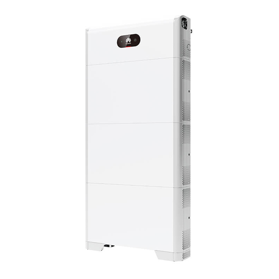
2.1 Overview Function The LUNA2000 battery consists of a power control module and battery expansion modules. It can store and release electric energy based on the requirements of the inverter management system. The input and output ports of the LUNA2000 battery are high-voltage direct current (HVDC) ports. - Page 17 Power level 5KW: The power level is 5 kW. Design code C0: product series of the power control module ● Model of battery expansion modules in the LUNA2000 battery: LUNA2000-5- Figure 2-2 Model number Table 2-2 Model description Meaning Value Product...
- Page 18 Figure 2-4 Battery capacity description Networking Application The LUNA2000 battery is applicable to the grid-tied systems of residential rooftop PV plants. Typically, a grid-tied system consists of PV strings, LUNA2000 batteries, an inverter, an AC switch, and a power distribution box (PDB).
-
Page 19: Appearance
2 Product Introduction Figure 2-5 Networking (dashed boxes indicate optional components) ● The input and output ports of the LUNA2000 battery are connected to the battery ports of the inverter. ● The following communication modes are supported by the LUNA2000 battery: –... - Page 20 (4) Battery expansion (5) Installation base (6) Black start switch modules (7) Heat sink Power Control Module The power of the power control module is 5 kW. Figure 2-7 Power control module Issue 01 (2020-10-20) Copyright © Huawei Technologies Co., Ltd.
-
Page 21: Label Description
(2) Boss for alignment (3) Battery cascading module terminals (B+/B–) (4) Battery cascading (5) COM port (COM) (6) Ground point terminals (B+/B–) (7) Heat sink (8) Ground point 2.3 Label Description Issue 01 (2020-10-20) Copyright © Huawei Technologies Co., Ltd. - Page 22 Grounding Indicates the position for connecting the PE cable. NO TE The labels are for reference only. Nameplate Nameplate of a power control module Issue 01 (2020-10-20) Copyright © Huawei Technologies Co., Ltd.
-
Page 23: Features
Intelligent O&M ● The factory defaults meet the requirements of target markets and the battery can be started by pressing only one button and supports black startup. Issue 01 (2020-10-20) Copyright © Huawei Technologies Co., Ltd. -
Page 24: Working Mode
The battery features easy O&M. 2.5 Working Mode The LUNA2000 converts HVDC generated by PV strings into low-voltage direct current (LVDC) through DC-to-DC conversion and stores the power in batteries. It can also convert LVDC into HVDC and feed the power into the power grid through the inverter. - Page 25 LUNA2000-(5-30)-S0 User Manual 2 Product Introduction Figure 2-11 Switchover among working modes Issue 01 (2020-10-20) Copyright © Huawei Technologies Co., Ltd.
-
Page 26: Application Scenarios And Settings
User Manual 3 Application Scenarios and Settings Application Scenarios and Settings The LUNA2000 battery is mainly used in grid-tied systems of residential rooftop PV plants. The system can be classified into the following three types based on application scenarios: ●... - Page 27 The grid-tied ESS supports inverter cascading. A maximum of three inverters can be cascaded. The batteries can be connected to one of the inverters for management. The batteries, power meter, and Smart Dongle need to be connected to the same inverter. Issue 01 (2020-10-20) Copyright © Huawei Technologies Co., Ltd.
- Page 28 When the capacity requirement is high, you can add inverters and batteries. A maximum of three inverters can be cascaded. Each battery connects to the inverter through an independent RS485 port and is managed by the inverter connected to it. Issue 01 (2020-10-20) Copyright © Huawei Technologies Co., Ltd.
-
Page 29: Setting The Grid-Tied Ess Mode
3.1.2 Setting the Grid-tied ESS Mode The grid-tied ESS has three main working modes: self-consumption, time-of-use, and excess fed to the grid. Issue 01 (2020-10-20) Copyright © Huawei Technologies Co., Ltd. - Page 30 ● In this mode, Maximum self-consumption is selected. By default, the charge cutoff capacity is 100% and the discharge cutoff capacity is 0% for Huawei LUNA2000 batteries. For details about how to change the charge or discharge cutoff capacity, see 6.3 Battery...
- Page 31 The charge from grid function must be enabled. ● A maximum of 14 time segments can be set. For details about how to set charge and discharge parameters, see 6.3 Battery Commissioning. Issue 01 (2020-10-20) Copyright © Huawei Technologies Co., Ltd.
- Page 32 Maximum (kW) determined by the local grid company. If charge there is no requirement, the value is the power maximum charge power of the ESS by allowed by default. the grid] Issue 01 (2020-10-20) Copyright © Huawei Technologies Co., Ltd.
- Page 33 PV module outputs 8 kW power, the inverter outputs 5 kW power, the loads consume 4 kW power, and the batteries charge 1 kW power. When the sunlight becomes weak, the PV module outputs 4 kW power, the inverter outputs Issue 01 (2020-10-20) Copyright © Huawei Technologies Co., Ltd.
-
Page 34: Grid-Tied And Off-Grid Ess
3.2.1 Grid-tied and Off-grid ESS Networking Networking 1: Inverter + Batteries The grid-tied and off-grid ESS consists of the PV strings, LUNA2000 batteries, inverter, AC switch, load, Backup Box, PDU, and grid. The grid connection status of the inverter is switched by using the Backup Box. - Page 35 The grid-tied and off-grid ESS supports inverter cascading. One inverter connects to and manages the batteries. The Backup Box can connect to only one inverter output. The batteries, power meter, and Smart Dongle need to be connected to the same inverter. Issue 01 (2020-10-20) Copyright © Huawei Technologies Co., Ltd.
- Page 36 Networking 3: Inverter (with Batteries) + Inverter (with Batteries) A maximum of three inverters can be cascaded in the grid-tied and off-grid ESS. The batteries, power meter, and Smart Dongle need to be connected to the same inverter. Issue 01 (2020-10-20) Copyright © Huawei Technologies Co., Ltd.
-
Page 37: Setting The Grid-Tied And Off-Grid Ess Mode
Backup Box. When the grid fails, the ESS supplies power to primary loads in backup mode. When the grid recovers, the ESS automatically switches back to the grid-tied mode. Issue 01 (2020-10-20) Copyright © Huawei Technologies Co., Ltd. - Page 38 Table 3-5 Grid-tied and off-grid parameter setting Parameter Description Value Range Off-grid mode If this parameter is set to Enable, the ESS ● Enable switches to the off-grid mode when the grid ● Disable fails. Issue 01 (2020-10-20) Copyright © Huawei Technologies Co., Ltd.
-
Page 39: Pure Off-Grid Ess
PV energy at night. 3.3.1 Pure Off-grid ESS Networking The pure off-grid ESS consists of the PV strings, LUNA2000 batteries, inverter, AC switch, and load. In off-grid mode, PV strings and batteries must be configured. -
Page 40: Setting The Pure Off-Grid Ess Mode
PV energy in batteries. When the sunlight is insufficient or there is no sunlight, the batteries discharge to supply power to loads. By default, the charge cutoff capacity of Huawei LUNA2000 batteries is 100% and the discharge cutoff capacity is 0%. For details about how to change the charge or discharge cutoff capacity, see 6.3 Battery... - Page 41 The battery does not discharge when it is discharged to the SOC. When sunlight is available on the next day, the battery starts to supply power to loads after being charged to a certain amount of electricity. Issue 01 (2020-10-20) Copyright © Huawei Technologies Co., Ltd.
-
Page 42: System Installation
For details about the number of deliverables delivered with the battery, see the in the packing case. 4.2 Preparing Tools and Instruments Type Tools and Instruments Installation Hammer drill (with a Torque socket wrench Torque wrench drill bit of 8 mm) Issue 01 (2020-10-20) Copyright © Huawei Technologies Co., Ltd. - Page 43 Cord end terminal Disassembly and PV-CZM-22100) crimper Assembly Tool (model: PV-MS-HZ open-end wrench) Cable tie Vacuum cleaner Multimeter (DC voltage measurement range ≥ 600 V DC) Marker Steel measuring tape Level Issue 01 (2020-10-20) Copyright © Huawei Technologies Co., Ltd.
-
Page 44: Determining The Installation Position
The battery can be floor-mounted and wall-mounted. The installation angle requirement is as follow: ● Do not install the battery at forward tilted, back tilted, side tilted, horizontal, or upside down positions. Issue 01 (2020-10-20) Copyright © Huawei Technologies Co., Ltd. -
Page 45: Equipment Installation
Reserve sufficient clearance around the battery to ensure sufficient space for installation and heat dissipation. Figure 4-1 Installation space 4.4 Equipment Installation 4.4.1 Floor-Mounted Installation Installation Precautions Figure 4-2 shows the dimensions of mounting holes for a battery. Issue 01 (2020-10-20) Copyright © Huawei Technologies Co., Ltd. - Page 46 M6x60 expansion bolts delivered with the battery are used to install the floor support and power control module. If the length and quantity of the bolts do not meet installation requirements, prepare M6 stainless steel expansion bolts by yourself. Issue 01 (2020-10-20) Copyright © Huawei Technologies Co., Ltd.
- Page 47 Otherwise, the mounting kit will not be securely installed on the wall or ground. ● Loosen the nut, spring washer, and flat washer of the expansion bolt at the bottom. Issue 01 (2020-10-20) Copyright © Huawei Technologies Co., Ltd.
- Page 48 WARNING After installing a module, install and tighten the connecting pieces and screws on the left and right sides of the module, and then install the next module. Issue 01 (2020-10-20) Copyright © Huawei Technologies Co., Ltd.
- Page 49 Figure 4-5 Installing the battery expansion modules and power control module Step 4 Secure the power control module to the wall. WARNING The power control module must be fixed on the wall to prevent it from falling down. Issue 01 (2020-10-20) Copyright © Huawei Technologies Co., Ltd.
-
Page 50: Wall-Mounted Installation
User Manual 4 System Installation Figure 4-6 Fixing the power control module ----End 4.4.2 Wall-Mounted Installation Installation Precautions Figure 4-7 shows the dimensions of mounting holes for the battery on the wall. Issue 01 (2020-10-20) Copyright © Huawei Technologies Co., Ltd. - Page 51 M6x60 expansion bolts delivered with the battery are used to fix the power control module. If the length and quantity of the bolts do not meet installation requirements, prepare M6 stainless steel expansion bolts by yourself. Issue 01 (2020-10-20) Copyright © Huawei Technologies Co., Ltd.
- Page 52 WARNING After installing a module, install and tighten the connecting pieces and screws on the left and right sides of the module, and then install the next module. Issue 01 (2020-10-20) Copyright © Huawei Technologies Co., Ltd.
- Page 53 Step 4 Secure the power control module to the wall. WARNING The power control module must be fixed on the wall to prevent the battery from falling down. Figure 4-9 Fixing power control module ----End Issue 01 (2020-10-20) Copyright © Huawei Technologies Co., Ltd.
-
Page 54: Electrical Connection
The cable colors shown in the electrical connection diagrams provided in this chapter are for reference only. Select cables in accordance with local cable specifications (green-and- yellow cables are only used for PE). Issue 01 (2020-10-20) Copyright © Huawei Technologies Co., Ltd. -
Page 55: Preparing Cables
(8 cross-sectional by the battery and cores) area: 0.20–0.35 customer battery to battery) ● Cable outer diameter: 6.2–7 Ground cable Single-core outdoor Prepared ● 10 mm copper cable by the customer Issue 01 (2020-10-20) Copyright © Huawei Technologies Co., Ltd. -
Page 56: Internal Electrical Connections Of The Battery
Internal cables are delivered with the battery. For details, see the Packing List in the packing case. 5.2.1 Installing an Internal Ground Cable Precautions D ANGER Ensure that the PE cable is securely connected. Otherwise, electric shocks may occur. Issue 01 (2020-10-20) Copyright © Huawei Technologies Co., Ltd. -
Page 57: Installing Internal Dc Terminals
Figure 5-2 Connecting the internal PE cable ----End 5.2.2 Installing Internal DC Terminals Step 1 Insert the positive and negative connectors delivered with the battery into the positive and negative battery cascading terminals (B+ and B–). Issue 01 (2020-10-20) Copyright © Huawei Technologies Co., Ltd. -
Page 58: Connecting Internal Signal Cables
Connecting Signal Cables Between the Power Control Module and Battery Expansion Modules Connect the communications terminals of the power control module and battery expansion modules in sequence and secure them using cable clips. Issue 01 (2020-10-20) Copyright © Huawei Technologies Co., Ltd. -
Page 59: External Electrical Connections Of The Battery
5.3 External Electrical Connections of the Battery Routing Cables Out of the Cable Hole Cut a cable hole based on the cabling mode, and route external cables through the cable hole. Issue 01 (2020-10-20) Copyright © Huawei Technologies Co., Ltd. -
Page 60: Installing A Pe Cable
● Wrap the wire crimping area with heat shrink tubing or insulation tape. The heat shrink tubing is used as an example. ● When using a heat gun, protect the equipment from being scorched. Issue 01 (2020-10-20) Copyright © Huawei Technologies Co., Ltd. - Page 61 Step 2 Connect the ground point of the power control module to the external ground point. Figure 5-7 Grounding the PE cable NO TE It is recommended that silica gel or paint be used around the ground terminal after the PE cable is connected. ----End Issue 01 (2020-10-20) Copyright © Huawei Technologies Co., Ltd.
-
Page 62: Installing Dc Input Power Cables
Use Staubli MC4 positive and negative metal terminals and DC connectors. Using incompatible positive and negative metal terminals and DC connectors may result in serious consequences. The caused equipment damage is not covered under any warranty or service agreement. Issue 01 (2020-10-20) Copyright © Huawei Technologies Co., Ltd. -
Page 63: Installing A Signal Cable
It is recommended that the COM port on the switch side be connected to the inverter and the COM port on the other side be connected to the cascaded battery. Issue 01 (2020-10-20) Copyright © Huawei Technologies Co., Ltd. - Page 64 5-3. When you insert the communications terminal of the power control module, the silk screens on the two sides of the communications port are different. Insert the communications terminal according to the following figures. Issue 01 (2020-10-20) Copyright © Huawei Technologies Co., Ltd.
- Page 65 LUNA2000-(5-30)-S0 User Manual 5 Electrical Connection Figure 5-11 Inserting the terminal Connecting a Signal Cable Prepare signal cable terminals for connecting to the inverter. Issue 01 (2020-10-20) Copyright © Huawei Technologies Co., Ltd.
-
Page 66: Optional) Cascading Batteries
LUNA2000-(5-30)-S0 User Manual 5 Electrical Connection Figure 5-12 Connecting inverter terminals 5.4 (Optional) Cascading Batteries Battery Cascading Cable Connection Figure 5-13 Battery cascading cable connection Issue 01 (2020-10-20) Copyright © Huawei Technologies Co., Ltd. - Page 67 Insert the communications terminal according to the following figures. Figure 5-14 Inserting the terminal Connecting a Signal Cable (Cascading) Prepare a signal cable terminal for connecting the power control module. Issue 01 (2020-10-20) Copyright © Huawei Technologies Co., Ltd.
-
Page 68: Installing The Cover
Figure 5-15 Cascading communication terminal 5.5 Installing the Cover After electrical connections are complete, check that cables are correctly and securely connected, install the external protective cover, and secure it using screws. Issue 01 (2020-10-20) Copyright © Huawei Technologies Co., Ltd. - Page 69 LUNA2000-(5-30)-S0 User Manual 5 Electrical Connection Figure 5-16 Installing the cover Issue 01 (2020-10-20) Copyright © Huawei Technologies Co., Ltd.
-
Page 70: System Commissioning
Unused terminal and port Unused terminals and ports are locked by watertight caps. Installation environment The installation space is proper, and the installation environment is clean and tidy. Issue 01 (2020-10-20) Copyright © Huawei Technologies Co., Ltd. -
Page 71: System Power-On
Blinking red Battery expansion module environment fast alarm Steady red The power control module is faulty. Steady red The battery expansion module is faulty. Steady red Steady red Faulty Battery system indicator Issue 01 (2020-10-20) Copyright © Huawei Technologies Co., Ltd. -
Page 72: Battery Commissioning
When the app connects to the inverter, a message is displayed, asking you to upgrade the inverter version. Dongle V100R001C00SPC117 and later versions support LUNA2000 battery. But the Smart Dongle cannot be upgraded locally. You need to perform the upgrade through the management system. The operation procedure will be updated later. -
Page 73: Battery Control
Function When the inverter connects to a battery, add the battery and set battery parameters. Adding a Battery To add a battery, choose Maintenance > Subdevice management on the home screen. Issue 01 (2020-10-20) Copyright © Huawei Technologies Co., Ltd. - Page 74 LUNA2000-(5-30)-S0 User Manual 6 System Commissioning Figure 6-3 Adding a battery Parameters Settings On the home screen, choose Power adjustment > Battery control, and set the battery parameters and working mode. Issue 01 (2020-10-20) Copyright © Huawei Technologies Co., Ltd.
- Page 75 Additional configuration is Maximum (kW) not required. charge power] Maximum Retain this parameter to the maximum ● Discharge: discharge power discharge power. Additional configuration is (kW) not required. Maximum discharge power] Issue 01 (2020-10-20) Copyright © Huawei Technologies Co., Ltd.
-
Page 76: Querying The Battery Status
Figure 6-5 Device monitoring 6.3.4 Battery Maintenance and Upgrade On the home screen, choose Maintenance > Battery upgrade and set related parameters. Issue 01 (2020-10-20) Copyright © Huawei Technologies Co., Ltd. - Page 77 Remaining charge/ Indicates the remaining discharge duration (min) charge and discharge duration. This parameter cannot be set. Charged/Discharged Indicates the charged or energy (kWh) discharged battery level. This parameter cannot be set. Issue 01 (2020-10-20) Copyright © Huawei Technologies Co., Ltd.
- Page 78 Figure 6-7 Downloading a file Step 2 Download the device upgrade package and grid code when an update is detected. Step 3 On the screen for downloading the upgrade package, tap Download. ----End Issue 01 (2020-10-20) Copyright © Huawei Technologies Co., Ltd.
-
Page 79: System Maintenance
Table 7-1 Maintenance checklist Check Item Check Method Maintenance Interval System Check periodically that the heat sinks Once every 6 to 12 cleanliness are free from obstacles and dust. months Issue 01 (2020-10-20) Copyright © Huawei Technologies Co., Ltd. -
Page 80: Troubleshooting
Alarm severities are defined as follows: ● Major: The battery shuts down or some functions are abnormal due to a fault. ● Minor: Some components of the battery are faulty but the battery can still work. Issue 01 (2020-10-20) Copyright © Huawei Technologies Co., Ltd. - Page 81 3. The battery power ventilation and heat dissipation. control module is abnormal. 3. If the ventilation and ambient temperature are normal, contact your dealer or Huawei technical support. Issue 01 (2020-10-20) Copyright © Huawei Technologies Co., Ltd.
- Page 82 DC switch, AC output switch, and inverter DC input switch in sequence. 4. If the alarm persists, contact your dealer or Huawei technical support. Issue 01 (2020-10-20) Copyright © Huawei Technologies Co., Ltd.
- Page 83 5 minutes. 3. Turn on the battery DC switch, inverter AC output switch, and DC input switch. 4. If the alarm persists, contact your dealer or Huawei technical support. Issue 01 (2020-10-20) Copyright © Huawei Technologies Co., Ltd.
- Page 84 3. If the ventilation and ambient temperature are normal, contact your dealer or Huawei technical support. Issue 01 (2020-10-20) Copyright © Huawei Technologies Co., Ltd.
- Page 85 If the sunlight is sufficient or AC expansio expansion module is low. reverse charging is allowed, the [Battery-1/2 battery expansion module module-1/2/3] battery undervol expansion modules can be tage charged when the inverter is running. Issue 01 (2020-10-20) Copyright © Huawei Technologies Co., Ltd.
-
Page 86: Battery Storage And Recharge
Battery Storage Requirements Place batteries according to the signs on the packing case during storage. Do not put batteries upside down or sidelong. Issue 01 (2020-10-20) Copyright © Huawei Technologies Co., Ltd. - Page 87 Interval Temperature 0°C–40°C 0°C ≤ T ≤ 25°C 15 months Not reaching the time for recharge: Use the batteries as soon as possible. Reaching the time for recharge: Recharge the batteries. Issue 01 (2020-10-20) Copyright © Huawei Technologies Co., Ltd.
- Page 88 The three-phase 10 kW inverter provides 10 kW power to charge batteries. It allows two charge units (six battery packs) to be charged at the same time. Other models can charge batteries with a power of less than 10 kW. Issue 01 (2020-10-20) Copyright © Huawei Technologies Co., Ltd.
- Page 89 Battery Recharging Cable Connection Connect cables by referring to 5 Electrical Connection. If two charge units need to be charged at the same time, cascade the batteries by referring to (Optional) Cascading Batteries. Issue 01 (2020-10-20) Copyright © Huawei Technologies Co., Ltd.
- Page 90 Step 3 Turn on the AC switch between the inverter and the grid. Step 4 Check that LED1 is steady green, LED2 is steady green, and LED3 is blinking green slowly. Issue 01 (2020-10-20) Copyright © Huawei Technologies Co., Ltd.
- Page 91 Step 8 After the battery is charged, switch off the inverter input AC circuit breaker and then the battery input circuit breaker. If other batteries need to be charged, repeat the preceding steps. ----End Issue 01 (2020-10-20) Copyright © Huawei Technologies Co., Ltd.
-
Page 92: Technical Specifications
240 mm x 670 mm x 150 mm Weight 12 kg Cooling mode Free cooling IP rating IP65 Communications RS485 and CAN (for cascading) Operating –25°C to +55°C temperature Operating humidity 5%–95% RH Maximum operating 4000 m altitude Issue 01 (2020-10-20) Copyright © Huawei Technologies Co., Ltd. -
Page 93: Luna2000-5-E0
Dimensions (H x W x 360 mm x 670 mm x 150 mm Weight 50kg Cooling mode Free cooling IP rating IP65 Operating –10°C to +55°C temperature Maximum operating 4000 m altitude Issue 01 (2020-10-20) Copyright © Huawei Technologies Co., Ltd. -
Page 94: Faq
Step 3 Lift the fuse box opening, remove the fuse, insert a new fuse into the slot, and close the fuse box. If you hear a click sound and the bulge on the side is inside the box, the fuse box is properly installed. Issue 01 (2020-10-20) Copyright © Huawei Technologies Co., Ltd. - Page 95 10 kA capacity Nominal fusing heat I2T Cold resistance 0.005 Ω value Package 14 mm x dimensions (the 51 mm dimension tolerance should be specified in the specifications provided by the supplier) Issue 01 (2020-10-20) Copyright © Huawei Technologies Co., Ltd.
-
Page 96: A Acronyms And Abbreviations
LUNA2000-(5-30)-S0 User Manual A Acronyms and Abbreviations Acronyms and Abbreviations application battery management system direct current feed-in tariff electromagnetic interference photovoltaic virtual power plant Issue 01 (2020-10-20) Copyright © Huawei Technologies Co., Ltd.