
Summary of Contents for ANDERSON-NEGELE BC110
- Page 1 Instruction Manual Anderson Instrument Co. Inc. 156 Auriesville Road Fultonville, NY 12072 1-800-833-0081 www.anderson-negele.com Instrument Model Number Instrument Serial Number BC110 Controller 30019 / 0.1 / 2017-10-1 / GM / NA...
-
Page 3: Table Of Contents
Table of Contents 1 Description ....................................5 1.1 Unit Description: ......................................5 1.2 Unit Features: ........................................5 1.3 Specifications: ........................................ 5 1.4 Dimensions: ........................................9 2 Installation ....................................10 2.1 General Mounting Hints: .................................... 10 2.2 Mounting Diagrams: ....................................10 3 Applications .................................... - Page 4 9.4 BC110 RS-232 Port Pinout ..................................41 10 Glossary of Terms ..................................42 11 Diagnosis and Troubleshooting ............................... 45 11.1 Response of BC110 on Error or Alarm: ..............................45 11.2 Diagnosis Flow Chart and Troubleshooting ............................46 11.3 Error & Warning Messages: ..................................47 11.3.1 Sensor/Process Alarms ..............................
-
Page 5: Description
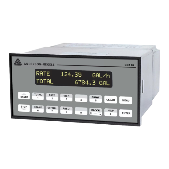
1.1 U ESCRIPTION The BC110 Flow Computer satisfies the rate, total and batching instrument requirements for a variety of pulse producing flowmeter types in liquid applications. Multiple flow equations and instrument functions are available in a single unit with many advanced features. - Page 6 PAGE 6 Enclosure Excitation Voltage Size: See Dimensions (section 2.2) 110/220 VAC Powered Units Depth behind panel: 6.5" including mating Menu Selectable: 5, 12 or 24 VDC @ 100mA connector 24 VDC Powered Units Type: DIN Menu Selectable: 5 or 12 VDC @ 100mA Materials: Plastic, UL94V-0, Flame retardant 12 VDC Powered Units Bezel: Textured per matt finish...
- Page 7 PAGE 7 Isolated Pulse output The isolated pulse is assigned to Volume Total. Isolation I/O/P: 500 V Pulse Output Form: Isolated Photomos Relay Maximum On Current: 125 mA Maximum Off Voltage: 30 VDC Saturation Voltage: 1.0 VDC Maximum Off Current: 0.1 mA Pulse Duration: User selectable: 10mSec, 100mSec Pulse output buffer: 8 bit...
- Page 8 Calibrate Analog Output using the Learn Feature Perform Excitation Output Test Examine or Dump Data Logger RS-232 Serial Port The BC110 has a general-purpose RS-232 Port which may be used for any one of the following purposes: Transaction Printing Data Logging Remote Metering by Modem (optional)
-
Page 9: Dimensions
In the modem mode, the BC110 is assumed to be operating in a remote metering role. In addition, the BC110 will be capable of initiating a call to a designed telephone number in the event of a metering malfunction. -
Page 10: Installation
INTS The BC110 Flow Computer should be located in an area with a clean, dry atmosphere which is relatively free of shock and vibration. The unit is installed in a 5.43" (138mm) wide by 2.68" (68mm) high panel cutout. (see Mounting Dimensions) To mount the Flow Computer, proceed as follows: a. -
Page 11: Applications
PAGE 1 1 PPLICATIONS 3.1 L IQUID OLUME Measurements: A flowmeter measures the actual volume in a liquid line. Calculations: For Flowmeters with Pulse Outputs, Volume flow is calculated using the flowmeter frequency output and the user entered K-Factor or Linearization Table. Output Results: •... -
Page 12: Batching
PAGE 1 2 3.2 B ATCHING Measurements: A flowmeter measures the actual volume in a liquid line. Calculations: For Flowmeters with Pulse Outputs, Volume flow is calculated using the flowmeter frequency output and the user entered K-Factor or Linearization Table. Output Results: Display Results Flow Rate, Batch Total, Non-Resettable Total... -
Page 13: Wiring
PAGE 1 3 4 WIRING 4.1 T YPICAL ATCHER IRING 4.2 T YPICAL OTAL IRING... -
Page 14: Unit Operation
5.1 F RONT ANEL PERATION ONCEPT FOR The BC110 is fully programmable through the front panel. Please review the following usage summary before attempting to use the instrument. HELP On-line help is provided to assist the operator in using this product. -
Page 15: Ratemeter/Totalizer Operation
PAGE 1 5 5.3 R ATEMETER OTALIZER PERATION The Ratemeter/Totalizer mode is used primarily to monitor flowrate and accumulated total. The relays can be used to trigger on flow rate, total, or alarms. 5.3.1 Password Protection for Rate/Total mode After an Operator and/or Supervisor Password is entered in the setup mode (see section 6.3, SETUP PASSWORD submenu), the unit will be locked. -
Page 16: Rs-232 Serial Port Operation In Rate/Total Mode
PAGE 1 6 5.3.5 RS-232 Serial Port Operation in Rate/Total mode The RS-232 serial port can be used for programming (using the Setup Disk) or for communicating to printers and computers in the Operating Mode (Run Mode). PC Communications: The Setup Disk also allows the user to query the unit for operating status such as Flow Rate, Flow Total, Presets, etc. -
Page 17: Password Protection For Batcher Mode
PAGE 1 7 flowrate. When the Batch Overrun is set, the unit will compensate for batch overruns by computing an averaged overrun value from the last four batches. This average is used to internally adjust the batch setpoint to minimize overrun. The maximum drain time must be set greater than the slowest valve response time for proper operation of this feature. -
Page 18: Relay Operation In Batcher Mode
PAGE 1 8 5.4.3 Relay Operation in Batcher mode Up to four relays are available (two standard) for alarm outputs. Preset 1 (RLY1) is reserved for batch amount, Preset 2 (RLY2) is reserved for prewarn. (see section 5.4 Batcher Operation for Relay 1 & Relay 2 functions) Preset 1 (RLY1) and Preset 2 (RLY2) are easily accessible by pressing the PRE 1 or PRE 2 key on the front panel. -
Page 19: Programming
RONT ANEL PERATION ONCEPT FOR ROGRAM The BC110 is fully programmable through the front panel. Please review the following usage summary before attempting to use the instrument. 6.1.1 Setup Mode: MODE CHANGES Pressing the MENU key will offer selections of RUN, SETUP, TEST. RUN is the normal operating mode for the instrument. -
Page 20: Ez Setup
PAGE 2 0 6.2 EZ S ETUP The EZ Setup routine is a quick and easy way to configure the unit for the most commonly used instrument functions. This setup assumes that you are measuring Volumetric Flow using a high level, DC Pulsing flow sensor. -
Page 21: Setup Menus
PAGE 2 1 6.3 S ETUP ENUS Top Level Setup Menu Sub-menu Groups... -
Page 22: Setup Sub-Menu
PAGE 2 2 6.4 S ETUP 6.4.1 SELECT EZ SETUP 6.4.2 INSTRUMENT TYPE Rate/Tot Batch NOTE: Max Drain time value must be greater than the slowest valve response time when using Batch Overrun Comp. -
Page 23: Setup Indicators (Total)
PAGE 2 3 6.4.3 SETUP INDICATORS (Total) 6.4.4 SETUP INDICATORS (Rate) -
Page 24: Setup Flow Input (Pulse - Cha & Cha=Chb)
PAGE 2 4 6.4.5 SETUP FLOW INPUT (Pulse - chA & chA=chB) NOTE: chA = Single Pulse chA=chB = Pulse checking missing pulses Qx1 = Quadrature Qx2 = Quadrature x 2... -
Page 25: Setup Flow Input (Pulse - Quadrature, Qx1 Or Qx2)
PAGE 2 5 6.4.6 SETUP FLOW INPUT (Pulse - Quadrature, Qx1 or Qx2) NOTE: chA = Single Pulse chA=chB = Pulse checking missing pulses Qx1 = Quadrature Qx2 = Quadrature x 2... -
Page 26: Setup Pulse Output
PAGE 2 6 6.4.7 SETUP PULSE OUTPUT 6.4.8 SETUP ANALOG OUTPUT... -
Page 27: Setup Relays
PAGE 2 7 6.4.9 SETUP RELAYS (Relay 1 & Relay 2) NOTE: In Batch mode, Relay 1 is reserved for Preset, Relay 2 is reserved for Prewarn or NA (not assigned). SETUP RELAYS (Relay 3 & Relay 4) NOTE: Settings for Relays 3 &... -
Page 28: Setup Control Inputs (Rate/Total)
PAGE 2 8 RELAY NOTES & CONSIDERATIONS 1. Relay activation is based on the computed readings not the displayed value. Therefore, the display damping factor will not affect the relay response time. The RELAY DELAY feature allows the user to enter a time delay for relay activation. -
Page 29: Setup Realtime Clock (Time)
PAGE 2 9 6.4.12 SETUP REALTIME CLOCK (Time) 6.4.13 SETUP REALTIME CLOCK (Date) -
Page 30: Serial Usage
PAGE 3 0 6.4.14 SERIAL USAGE... -
Page 31: Setup Datalog/Print (Configure)
PAGE 3 1 6.4.15 SETUP DATALOG/PRINT (Configure) -
Page 32: Setup Datalog/Print (Select_List)
PAGE 3 2 6.4.16 SETUP DATALOG/PRINT (Select_list) List Items: TOTAL RATE PRE1 PRE3 GRAND PRE2 PRE4 TIME 6.4.17 ADMINISTRATIVE SETUP NOTE: Accessed only with supervisor password. -
Page 33: Setup Network Card
PAGE 3 3 6.4.18 SETUP NETWORK CARD (optional) -
Page 34: Principals Of Operation
RINCIPALS OF PERATION 7.1 G ENERAL The BC110 Flow Computer uses several internal calculations to compute the input frequency based on specific data input. Several computations are performed to yield flow or linearized flow. 7.2 F QUATIONS Uncompensated Flow Computation: Pulse Input;... -
Page 35: Test, Service And Maintenance
PAGE 3 5 ERVICE AND AINTENANCE 8.1 T ENUS TOP LEVEL TEST MENUS... -
Page 36: Test Sub-Menus
PAGE 3 6 8.2 T ENUS 8.2.1 Audit Trail 8.2.2 Error History 8.2.3 Print System Setup... -
Page 37: Keypad Test
PAGE 3 7 8.2.4 Keypad test 8.2.5 Display test 8.2.6 Calibrate 0 mA Out 8.2.7 Calibrate 20mA... -
Page 38: Pulse Input Test
PAGE 3 8 8.2.8 Pulse input test 8.2.9 Analog out test 8.2.10 Excitation out test 8.2.11 Pulse out test... -
Page 39: 8.2.12 Relay Test
PAGE 3 9 8.2.12 Relay test 8.2.13 Control inputs test 8.2.14 Data logger utility... -
Page 40: Internal Fuse Replacement
PAGE 4 0 8.3 I NTERNAL EPLACEMENT Instructions: 1. Make sure you follow proper E.S.D. Precautions. All persons performing this replacement must follow proper grounding procedures. 2. Turn the power to the unit off. 3. Disconnect the two-piece connector rear terminal block, leaving all connections in place. 4. -
Page 41: Rs-232 Serial Port
9 RS-232 S ERIAL 9.1 RS-232 P ESCRIPTION The BC110 has a general purpose RS-232 Port which may be used for any one of the following purposes: Transaction Printing Data Logging Remote Metering by Modem (optional) Computer Communication Link Configuration by Computer... -
Page 42: Glossary Of Terms
Alarms will reassert themselves if alarm conditions are still present. Analog Output The analog signal (4-20mA) that is generated by the BC110. It can correspond to the Rate or Total. This output is used primarily for transmission of process information to remote systems. - Page 43 A value set at which any flow measurements read below this value will be ignored. Low Pass Filter A low pass filter passes low input frequencies while blocking high frequencies. In the BC110, this is the maximum input count speed to be encountered in an application. It is expressed in counts per second (Hz).
- Page 44 Pulse Output The pulse output of the BC110 is available for remote accumulation of the total or sent to peripheral devices, such as a PLC. The output can be scaled using the Pulse Output Scaling Constant.
-
Page 45: Diagnosis And Troubleshooting
ESPONSE OF RROR OR LARM Error and warning indications which occur during operation are indicated in the RUN mode alternately with the measured values. The BC110 Flow Computer has three types of error: TYPE OF ERROR DESCRIPTION Sensor/Process Alarms Errors detected due to sensor failure or... -
Page 46: Diagnosis Flow Chart And Troubleshooting
PAGE 4 6 11.2 D IAGNOSIS HART AND ROUBLESHOOTING All instruments undergo various stages of quality control during production. The last of these stages is a complete calibration carried out on state-of-the-art calibration rigs. A summary of possible causes is given below to help you identify faults. -
Page 47: Error & Warning Messages
PAGE 4 7 11.3 E & W RROR ARNING ESSAGES 11.3.1 Sensor/Process Alarms 11.3.2 Self Test Alarms... -
Page 49: Warranty And Return Statement
PAGE 4 9 13 W ARRANTY AND ETURN TATEMENT These products are sold by The Anderson Instrument Company (Anderson) under the warranties set forth in the following paragraphs. Such warranties are extended only with respect to a purchase of these products, as new merchandise, directly from Anderson or from an Anderson distributor, representative or reseller, and are extended only to the first buyer thereof who purchases them other than for the purpose of resale. - Page 50 ANDERSON INSTRUMENT CO. LP • 400 BRITANNIA RD. EAST, UNIT 1 • MISSISSAUGA, ONTARIO L4Z 1X9 • CANADA • 905-603-4358 • FAX 905-568-1652 NEGELE MESSTECHNIK GmbH (A Division of Anderson) • RAIFFEISENWEG 7 • D-87743 EGG A. D. GÜNZ • GERMANY • +49 (0) 8333/9204-0 • FAX +49 (0) 8333/9204-49 www.anderson-negele.com...