Chapters
Table of Contents

Related Manuals for Samson 3510 Series


Summary of Contents for Samson 3510 Series
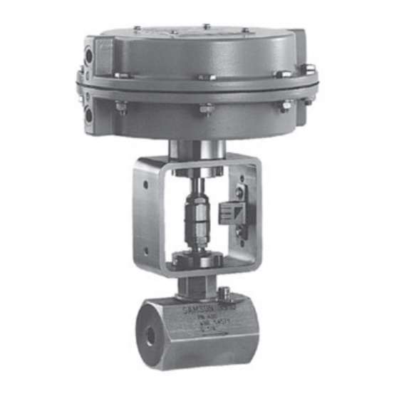
- Page 1 EB 8091 EN Translation of original instructions Type 3510-1 (left) and Type 3510-7 (right) Pneumatic Control Valves Type 3510 Micro-flow Valve · DIN version In combination with an actuator, e.g. a Type 3271 or Type 3277 Pneumatic Actuator Edition May 2020...
- Page 2 Note on these mounting and operating instructions These mounting and operating instructions assist you in mounting and operating the device safely. The instructions are binding for handling SAMSON devices. The images shown in these instructions are for illustration purposes only. The actual product may vary.
-
Page 3: Table Of Contents
Contents Safety instructions and measures ..............1-1 Notes on possible severe personal injury ............1-4 Notes on possible personal injury ..............1-5 Notes on possible property damage .............1-7 Warnings on the device ................1-8 Markings on the device ................2-1 Valve body inscription .................2-1 Actuator nameplate ..................2-1 Material numbers ..................2-1 Label when an adjustable packing is installed ..........2-2 Design and principle of operation ...............3-1... - Page 4 Removal ....................11-1 11.1 Removing the valve from the pipeline ............11-2 11.2 Removing the actuator from the valve ............11-2 Repairs ....................12-1 12.1 Returning devices to SAMSON ..............12-1 Disposal ....................13-1 Certificates ....................14-1 Annex......................15-1 15.1 Tightening torques, lubricants and tools ............15-1 15.2 Spare parts ....................15-1 15.3...
-
Page 5: Safety Instructions And Measures
In case operators intend to use the control valve in other applications or conditions than specified, contact SAMSON. SAMSON does not assume any liability for damage resulting from the failure to use the de- vice for its intended purpose or for damage caused by external forces or any other external factors. - Page 6 (see associated actuator documentation). When the valve is combined with a SAMSON Type 3271 or Type 3277 Pneumatic Actuator, the valve moves to a certain fail- safe position (see the 'Design and principle of operation' section) upon supply air or control signal failure.
- Page 7 Start-up and shutdown procedures fall within the scope of the operator's duties and, as such, are not part of these mounting and operating instructions. SAMSON is unable to make any statements about these procedures since the operative details (e.g. differential pressures and temperatures) vary in each individual case and are only known to the operator.
-
Page 8: Notes On Possible Severe Personal Injury
− u AB 0100 for tools, tightening torques and lubricant − For oxygen service: Manual u H 01 − Manual u H 02: Appropriate Machinery Components for SAMSON Pneumatic Control Valves with a Declaration of Conformity of Final Machinery 1.1 Notes on possible severe personal injury DANGER Risk of bursting in pressure equipment. -
Page 9: Notes On Possible Personal Injury
Safety instructions and measures 1.2 Notes on possible personal injury WARNING Risk of burn injuries due to hot or cold components and pipelines. Depending on the process medium, valve components and pipelines may get very hot or cold and cause burn injuries. Î... - Page 10 Risk of personal injury due to preloaded springs. Valves in combination with pneumatic actuators with preloaded springs are under ten- sion. These control valves with SAMSON pneumatic actuators can be identified by the long bolts protruding from the bottom of the actuator.
-
Page 11: Notes On Possible Property Damage
Risk of valve damage due to the use of unsuitable tools. Certain tools are required to work on the valve. Î Only use tools approved by SAMSON (u AB 0100). Risk of valve damage due to the use of unsuitable lubricants. The lubricants to be used depend on the valve material. Unsuitable lubricants may cor- rode and damage surfaces. -
Page 12: Warnings On The Device
Safety instructions and measures NOTICE Risk of the process medium being contaminated through the use of unsuitable lubricants and/or contaminated tools and components. Î If necessary, keep the valve and the tools used free from solvents and grease. Î Make sure that only suitable lubricants are used. 1.4 Warnings on the device Warning Meaning of the warning... -
Page 13: Markings On The Device
2.1 Valve body inscription ture and body gasket) are matched to exact- ly fit each other and marked as follows: Seat − Material number SAMSON 3510 − SAMSON consecutive number Plug − Material number − SAMSON consecutive number − K coefficient and characteristic Anti-rotation fixture (on the trim) Valve size: DIN: DN ·... -
Page 14: Label When An Adjustable Packing Is Installed
Markings on the device 2.4 Label when an adjustable packing is installed An adjustable packing is used to seal the valve stem, which must be adjusted after the valve has been installed in the pipeline. See 'Leak test' in the 'Installation' section. An in- structional label is affixed to the outside of the yoke (see Fig. 2-3). -
Page 15: Design And Principle Of Operation
Depending on how the compression springs seal: one anti-rotation fixture between the are arranged in the SAMSON Type 3271 body and insulating section/bellows seal as and Type 3277 Pneumatic Actuator, the well as one anti-rotation fixture between the... - Page 16 Design and principle of operation Body A27.3 Plug with plug stem A27.1 Seat Body gasket Anti-rotation fixture Intermediate piece Fillister head screw A27.2 Slotted round nut Threaded bushing (packing nut) Yoke Travel indicator scale Hex nut Packing Actuator stem Ring nut A27.1 Stem connector nut A27.2 Bearing sleeve (bottom part of the stem connector)
-
Page 17: Versions
Actuators In these instructions, the preferable combina- tion with a SAMSON Type 3271 or Type 3277 Pneumatic Actuator is described. The pneumatic actuator (with or without handwheel) can be replaced by another pneumatic actuator in a different size, but with the same travel. -
Page 18: Additional Fittings
(item no. 1400-9031) can be of the valve and installing a bypass line. The ordered from SAMSON. Refer to the mount- bypass ensures that the plant does not need ing and operating instructions of the corre-... -
Page 19: Technical Data
Note More information is available in Data Sheet Noise emissions u T 8091. SAMSON is unable to make general state- ments about noise emissions. The noise emis- Compliance sions depend on the valve version, plant fa- The Type 3510 Valve bears both the CE and cilities and process medium. - Page 20 Design and principle of operation Dimensions and weights Table 3-1: Dimensions in mm for Type 3510 Valve Connection Female thread Welding ends Flanges Valve G/NPT DN 10, 15, 25 DN 10 DN 15 DN 25 PN 40 PN 63 to 160 1) PN 250 to 320 PN 400 –...
- Page 21 Design and principle of operation Dimensional drawings SW50 Type 3510 as angle valve with Type 3510 as globe valve with female thread female thread, with bellows seal or insulating section EB 8091 EN...
- Page 22 Design and principle of operation Type 3510 · Valve body with flanges and welding ends Note Dimensions and weights for Type 3271 and Type 3277 Pneumatic Actuators with 120 cm² actuator area can found in the Data Sheet u T 8310-1. EB 8091 EN...
-
Page 23: Shipment And On-Site Transport
2. Check the shipment for transportation Î Stay clear of suspended or moving damage. Report any damage to loads. SAMSON and the forwarding agent Î Close off and secure the transport paths. (refer to delivery note). 3. Determine the weight and dimensions of... -
Page 24: Transporting The Valve
Shipment and on-site transport 4.3.1 Transporting the valve 4.3.2 Lifting the valve The control valve can be transported using Due to the low service weight, lifting equip- lifting equipment (e.g. crane or forklift). ment is not absolutely necessary to lift the control valves (e.g. -
Page 25: Storing The Valve
− Do not place any objects on the control Î Observe the storage instructions. valve. Î Avoid long storage times. Î Contact SAMSON in case of different Special storage instructions for elastomers storage conditions or long storage peri- Elastomer, e.g. actuator diaphragm ods. - Page 26 EB 8091 EN...
-
Page 27: Installation
Work position Î Contact SAMSON if the mounting posi- The work position for the control valve is the tion is not as specified above. front view looking onto the operating con- Support or suspension trols (including valve accessories). -
Page 28: Preparation For Installation
Installation Table 5-1: Inlet and outlet lengths Flow rate Inlet length Outlet length a x DN b x DN State of process Valve conditions Inlet length a Outlet length b medium Ma ≤ 0.3 0.3 ≤ Ma ≤ 0.7 Ma ≤ 0.3 1) 0.3 ≤ Ma ≤ 0.7 1) Vapor Saturated steam (percentage of condensate > 5 %) Free of cavitation/w < 10 m/s Cavitation producing... -
Page 29: Installing The Device
NOTICE work. Risk of valve damage due to the use of Î Flush the pipelines. unsuitable tools. Î Only use tools approved by SAMSON Note (u AB 0100). The plant operator is responsible for clean- ing the pipelines in the plant. EB 8091 EN... -
Page 30: Mounting The Actuator Onto The Valve
(see associated actuator 7. Attach a support or suspension on the documentation). valve, if necessary. Depending on the version, SAMSON control b) Version with welding ends valves are either delivered with the actuator already mounted on the valve or the valve 1. -
Page 31: Testing The Installed Valve
Installation 5.4 Testing the installed valve cessories not fitted with noise-reducing fit- tings. Both can damage hearing. Î Wear hearing protection when working DANGER near the valve. Risk of bursting due to incorrect opening of pressurized equipment or components. Valves and pipelines are pressure equipment WARNING WARNING that may burst when handled incorrectly. -
Page 32: Leak Test
Installation 5. Check the valve for leakage to the atmo- WARNING sphere. Risk of personal injury due to preloaded 6. Depressurize the pipeline section and springs. valve. Actuators with preloaded springs are under 7. Rework any parts that leak (see informa- tension. -
Page 33: Fail-Safe Position
Installation Î Check the travel reading at the travel in- dicator scale. 5.4.3 Fail-safe position Î Shut off the signal pressure line. Î Check whether the valve moves to the fail-safe position (see the 'Design and principle of operation' section). 5.4.4 Pressure test The plant operator is responsible for per-... - Page 34 EB 8091 EN...
-
Page 35: Start-Up
Start-up 6 Start-up Î Wear hearing protection when working near the valve. The work described in this section is only to be performed by personnel appropriately qualified to carry out such tasks. WARNING WARNING Crush hazard arising from actuator and WARNING plug stem moving. -
Page 36: Supply Pressures
Start-up 6.2 Putting the control valve Before start-up or putting the valve back into service, make sure the following conditions (back) into operation are met: 1. Allow the valve to cool down or warm up − The valve is properly installed into the to reach ambient temperature before pipeline (see the 'Installation' section). -
Page 37: Operation
Operation 7 Operation Î Wear hearing protection when working near the valve. Immediately after completing start-up or put- ting the valve back into operation, the valve is ready for use. WARNING WARNING Crush hazard arising from actuator and WARNING plug stem moving. Risk of burn injuries due to hot or cold Î... -
Page 38: Normal Operation
Operation 7.1 Normal operation The handwheel of valves with actuators fitted with a handwheel must be in the neutral po- sition during normal operation. 7.2 Manual operation Valves with actuators fitted with a handwheel can be manually closed or opened in case of supply air failure. -
Page 39: Malfunctions
Malfunctions 8 Malfunctions Read hazard statements, warnings and caution notes in the 'Safety instructions and mea- sures' section. 8.1 Troubleshooting Malfunction Possible reasons Recommended action Actuator and plug stem Actuator is blocked. Check attachment. does not move on de- Remove the blockage. mand. -
Page 40: Emergency Action
Malfunctions Malfunction Possible reasons Recommended action The valve leaks to the Defective packing Replace packing (see the 'Servicing' section) or atmosphere (fugitive contact our after-sales service. emissions). Packing tightened incor- Adjust the packing (see information under rectly. 'Adjusting the packing' in the 'Testing the installed valve' section). -
Page 41: Servicing
Servicing 9 Servicing Î Allow components and pipelines to cool down or warm up to reach ambient tem- The work described in this section is only to perature. be performed by personnel appropriately Î Wear protective clothing and safety qualified to carry out such tasks. gloves. - Page 42 Risk of valve damage due to the use of Risk of personal injury due to preloaded unsuitable tools. springs. Î Only use tools approved by SAMSON Actuators with preloaded springs are under (u AB 0100). tension. They can be identified by the long bolts protruding from the bottom of the actu- ator.
-
Page 43: Periodic Testing
Servicing 9.1 Periodic testing Note The control valve was checked by SAMSON Depending on the operating conditions, before it left the factory. check the valve at certain intervals to prevent − Certain test results certified by SAMSON a possible failure before it can occur. Opera-... - Page 44 Servicing Inspection and testing Action to be taken in the event of a negative result: Check the test connection and bellows Put the control valve out of operation (see the 'Decommis- seal (if used) for external leakage. sioning' section). To repair the bellows section, contact our WARNING! Risk of personal injury due after-sales service (see the 'Repairs' section).
-
Page 45: Body Gasket
Servicing Body Plug with plug stem A27.3 Seat A27.1 Body gasket Anti-rotation fixture Intermediate piece Fillister head screw A27.2 Slotted round nut Threaded bushing (packing nut) Yoke Travel indicator scale Hex nut Packing Actuator stem Ring nut A27.1 Stem connector nut A27.2 Bearing sleeve (bottom part of the stem connector) A27.3 Lock nut... -
Page 46: Preparing The Valve For Service Work
Servicing 9.2 Preparing the valve for 9.3 Mounting the valve after service work service work 1. Lay out the necessary material and tools 1. Mount actuator. See associated actuator to have them ready for the service work. documentation. 2. Put the control valve out of operation (see 2. -
Page 47: Replacing The Gasket
Servicing 9.4.1 Replacing the gasket b) Version with insulating section a) Standard version See Fig. 9-1 and Fig. 9-2 See Fig. 9-1 1. Loosen the slotted nut (11) at the valve. Remove the yoke (13) from the interme- 1. Loosen the slotted nut (11) at the valve. diate piece (4). - Page 48 Servicing 11. Insert a new gasket (2.3) into the body. inscribed on it) with the bent end facing upward over the intermediate piece (4). 12. Apply a suitable lubricant to the thread of the insulating section (28). 21. Insert the fillister head screw (23) through both parts of the anti-rotation fixture 13.
- Page 49 Servicing Legend for Fig. 9-2 Intermediate piece Seal Plug stem extension Fillister head screw 24.1 Bottom anti-rotation fixture 24.2 Top anti-rotation fixture (two-piece) Washer Hex nut Washer Insulating section 24.2 24.2 c) Version with bellows seal See Fig. 9-1 and Fig. 9-3 1. Loosen the slotted nut (11) at the valve. Remove the yoke (13) from the interme- diate piece (4).
-
Page 50: Anti-Rotation Fixture
Servicing 8. Loosen the fillister head screw (6) on the inscribed on it) from the top over the bel- bottom anti-rotation fixture (3.5). lows seal (7). 9. Version without test connection: remove 16. Fix the anti-rotation fixture (3.5) in place the anti-rotation fixture (3.5) from the with the fillister head screw (6). -
Page 51: Replacing The Packing
Servicing Legend for Fig. 9-3 Plug stem with metal bellows Seal (on intermediate piece) Bottom anti-rotation fixture Intermediate piece Bellows seal Fillister head screw 24.2 Top anti-rotation fixture (two-piece) Washer Hex nut Washer 24.2 24.2 Test connection 9.4.2 Replacing the packing NOTICE Risk of control valve damage due to incor- rect servicing. -
Page 52: Threaded Bushing (Packing Nut)
Servicing 6. Apply a suitable lubricant to all the pack- 11. Place the yoke (13) onto the intermediate ing parts. piece (4) and secure with slotted nut (11). Observe tightening torques. 7. Carefully slide the packing parts over the plug stem into the packing chamber us- ing a suitable tool. -
Page 53: Replacing The Seat And Plug
Servicing 9.4.3 Replacing the seat and a) Standard version plug See Fig. 9-1 1. Loosen the slotted nut (11) at the valve. NOTICE Remove the yoke (13) from the interme- Risk of control valve damage due to incor- diate piece (4). rect servicing. -
Page 54: Hex Nut
Servicing 14. Place the intermediate piece (4) together 6. Remove the bottom section of the top with the plug (2.1) onto the body. Use a anti-rotation fixture (24.2) from the suitable tool to screw it into the body (1). insulating section (28). Observe tightening torques. - Page 55 Servicing 19. Place the insulating section (28) together onto the screw and fix in place with the with the plug (2.1) and plug stem exten- hex nut (26). sion (22) onto the body. Use a suitable 27. Place the yoke (13) onto the intermediate tool to screw it into the body (1).
-
Page 56: Ordering Spare Parts And Operating Supplies
Servicing 9.5 Ordering spare parts and operating supplies Contact your nearest SAMSON subsidiary or SAMSON's After-sales Service for infor- mation on spare parts, lubricants and tools. Spare parts See Annex for details on spare parts. Lubricant See document u AB 0100 for details on suitable lubricants. -
Page 57: Decommissioning
Decommissioning 10 Decommissioning WARNING The work described in this section is only to Risk of personal injury due to pressurized be performed by personnel appropriately components and process medium being qualified to carry out such tasks. discharged. Î Do not loosen the screw of the test con- nection while the valve is pressurized. - Page 58 Decommissioning (e.g. due to seizing up after remaining in 3. Disconnect and lock the pneumatic air the same position for a long time), re- supply to depressurize the actuator. lease any stored energy in the actuator 4. Release any stored energy. (e.g.
-
Page 59: Removal
Removal 11 Removal WARNING WARNING The work described in this section is only to Risk of personal injury due to residual be performed by personnel appropriately process medium in the valve. qualified to carry out such tasks. While working on the valve, residual medium can flow out of the valve and, depending on its properties, cause personal WARNING... -
Page 60: Removing The Valve From The Pipeline
Removal 11.1 Removing the valve from the pipeline a) Version with female thread or flanges 1. Support the valve to hold it in place when separated from the pipeline (see the 'Shipment and on-site transport' sec- tion). 2. Unfasten the valve or unbolt the flange joint. -
Page 61: Repairs
Î Do not perform any repair work on your side of your shipment so that the docu- own. ments are clearly visible. Î Contact SAMSON's After-sales Service 4. Send the shipment to the address given for repair work. on the RMA. - Page 62 12-2 EB 8091 EN...
-
Page 63: Disposal
Disposal 13 Disposal Î Observe local, national and internation- al refuse regulations. Î Do not dispose of components, lubricants and hazardous substances together with your household waste. EB 8091 EN 13-1... - Page 64 13-2 EB 8091 EN...
-
Page 65: Certificates
Certificates 14 Certificates The declarations are included on the next pages: − Declaration of conformity in compliance with Machinery Directive 2006/42/EC for Types 3510-1 and 3510-7 Control Valves on page 14-2 − Declaration of incorporation in compliance with Machinery Directive 2006/42/EC for the Type 3510 Valve with other actuators other than Types 3271 and 3277 Actuators on page 14-3... - Page 66 14-2 EB 8091 EN...
- Page 67 EB 8091 EN 14-3...
- Page 68 14-4 EB 8091 EN...
-
Page 69: Annex
Annex 15 Annex 15.1 Tightening torques, lubricants and tools u AB 0100 for tools, tightening torques and lubricants 15.2 Spare parts Body Snap ring Trim Plug stem extension Plug with plug stem Fillister head screw Seat 24.1 Bottom anti-rotation fixture Body gasket 24.2 Top anti-rotation fixture (two-piece) Anti-rotation fixture Washer... - Page 70 Annex 24.2 24.2 24.2 24.1 15-2 EB 8091 EN...
-
Page 71: After-Sales Service
You can reach our after-sales service at [email protected]. Addresses of SAMSON AG and its subsid- iaries The addresses of SAMSON AG, its subsid- iaries, representatives and service facilities worldwide can be found on our website (www.samsongroup.com) or in all SAMSON product catalogs. - Page 72 15-4 EB 8091 EN...
- Page 76 EB 8091 EN SAMSON AKTIENGESELLSCHAFT Weismüllerstraße 3 · 60314 Frankfurt am Main, Germany Phone: +49 69 4009-0 · Fax: +49 69 4009-1507 [email protected] · www.samsongroup.com...