
Related Manuals for Huawei OptiXRTN 980L


Summary of Contents for Huawei OptiXRTN 980L
- Page 1 OptiX RTN 980L Radio Transmission System V100 Quick Installation Guide (Integrated LH) Issue: 02 Date: 2019-04-30 HUAWEI TECHNOLOGIES CO., LTD.
- Page 2 Notice The purchased products, services and features are stipulated by the contract made between Huawei and the customer. All or part of the products, services and features described in this document may not be within the purchase scope or the usage scope. Unless otherwise specified in the contract, all statements, information, and recommendations in this document are provided "AS IS"...
-
Page 3: Table Of Contents
Contents Precautions Purchase List (North America) Installation Tools Equipment Components Cabinet Cables Installation Process Commissioning Process Installing Cabinet Cables Installing Power Cables Installing Ground Cables Laying out Cabinet Cables Installing IDU Cables Installing IF Cables Installing Ethernet Service Cables Installing XPIC Cables Installing Fibers Installing E1 Cables Installing STM-1e Cables... - Page 4 Contents Installing an Elliptical Waveguide Assembling Connectors Hoisting an Elliptical Waveguide Laying Out an Elliptical Waveguide Grounding an Elliptical Waveguide Waterproofing Outdoor Connectors Installing a Dehydrator Dehydrator Connection Diagram Dehydrator Alarm Cable Connection Powering On the Equipment Configuring the NE Data Aligning the Antennas Aligning the Single-Polarized Antennas Aligning the Dual-Polarized Antennas...
-
Page 5: Precautions
When performing operations on Huawei products or equipment, strictly observe related safety precautions and special safety instructions. The safety precautions in this document are only some that Huawei can predict. Huawei is not liable for any consequences that result from violation of common safety regulations or equipment production and usage regulations. - Page 6 Anti-corrosion measures are required if an RTN 980L is installed in a location that is prone to corrosion. Contact your local Huawei office for details. A location is prone to corrosion if it is: Within 3.7 km ( 12139 ft ) of an ocean or a salt water lake Within 3 km ( 9843 ft ) of a heavy pollution source, such as a smelting factory or coal mine...
- Page 7 Precautions for Equipment Operating Environment The operating environment for the integrated LH complies with ETSI EN 300 019-1-3 class 3.2 standards. Recommended operating environment To ensure the reliability of equipment, an equipment room must be equipped with dedicated air conditioners to control the temperature and humidity within the following ranges: •Temperature: 15º...
- Page 8 Precautions for Elliptical Waveguide Transportation and Storage Do not place the drum of Always place the drum of the elliptical waveguide the elliptical waveguide horizontally. vertically and fasten it.
- Page 9 Instructions and Precautions for Handling Boards CAUTION Do not hold a board without hand protection. Wear an ESD wrist strip or ESD gloves before handling a board. Wearing ESD gloves Wearing an ESD strip Holding a board without hand protection CAUTION Hold the front panel of a board with hands.
- Page 10 Precautions for Handling the Toggle Lever Switch • Position and description of the toggle lever switch O: OFF CAUTION •Turn the toggle lever switch only after gently pulling it out. •Switch off power before you remove or insert IF cables. I: ON •Turning on the switch Pull the switch out gently.
-
Page 11: Purchase List (North America)
Purchase List (North America) The following table lists materials not included in Huawei auxiliary material packages. Purchase these materials before installation. All installation operations in this document are only for your reference. Item Sub-item Remarks It is advised to use 6 AWG electronic power cables, each (1) PDU power cable of which spans over a maximum distance of 8.8 m (29 ft). -
Page 12: Installation Tools
Installation Tools Measuring tape Level Phillips screwdriver Flat-head screwdriver Adjustable wrench Wire clippers Socket suite Torque wrench Hex key Crimping tool Wire stripper RJ45 crimping tool Diagonal pliers COAX crimping tool Needle-nose pliers File Multimeter Heat gun Open-end wrench Combination pliers Segmented blade Hammer drill Marker... - Page 13 Installation Tools Pulley Lifting sling Compass Flaring tool kit Hoisting grip Hacksaw Safety belt Protection belt Slip-proof glove Safety helmet Anti-skid shoes...
-
Page 14: Equipment Components
Equipment Components Cabinet NOTE Branching units (BUs), RFUs, an IDU, and IF/RF cables were already installed in a cabinet before delivery. 300 mm ( 12 in ) 600 mm ( 24 in ) 2200 mm ( 87 in ) RTN 980L... -
Page 15: Rfu
Front Rear and side SD filter Tx filter NOTE Rx filter BUs are available in two models: BU-SD and BU-NonSD. Compared with a BU-NonSD, a BU-SD has additional SD filters. BU-SDs are used as an example. RF port L-shaped adapter IF port NOTE •An RFU has been installed on an L-shaped adapter. -
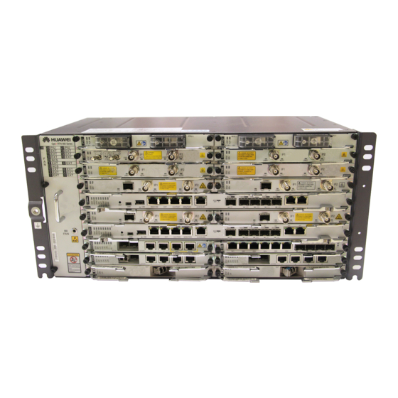
Page 16: Idu
Front View NOTE •In XPIC configuration mode, if RFUs and ISV3 boards work together, it is recommended that RFUs in the same polarization direction connect to ISV3 boards on the same side, and the slot priority is as follows: •Slot 13 > Slot 11 > Slot 9 > Slot 7 > Slot 5 •Slot 14 >... -
Page 17: Cables
Cables Flexible waveguide H plane E plane Elliptical waveguide E plane H plane Rigid waveguide Long rigid Short rigid waveguide waveguide... -
Page 18: Installation Process
Installation Process Assembling the Start Antenna-side Installing Power Connector Cables Page 34 Pages 19 to 20 Installing an Installing a Hoisting the Installing Ground Elliptical Waveguide Antenna Cabinet Cables Page 21 see N63E Cabinet See the Antenna Page 35 Installation Guide Installation Guide. -
Page 19: Commissioning Process
Commissioning Process Start Powering On the Page 50 Equipment Configuring the NE Page 51 Data (by Using the Web LCT) Pages Aligning the Pages Aligning the Single- 52 to 54 Antennas 52 to 53 Polarized Antennas Checking the Radio Pages Aligning the Dual- Page 54 Link Status... -
Page 20: Installing Cabinet Cables
Installing Cabinet Cables Installing Power Cables (1/2) Installing power cables Ground -48 V power cable (black) cable (blue) RTN1 (+) RTN1 (+) NEG1 (-) NEG1 (-) -48 V -48 V -48 V -48 V... - Page 21 Installing Power Cables (2/2) Check the fuse current of the external power supply. Recommended Current Value of the External Fuse 40 A Check the voltage and polarity of the external power supply. Standard Voltage of the Input Power Allowable Voltage Range –48 V ( DC ) –38.4 V to –57.6 V ( DC ) –60 V ( DC )
-
Page 22: Installing Ground Cables
Installing Ground Cables Installing Cabinet Ground Cables NOTE •Connect the cabinet ground cable to the ground bar in the equipment room. Ground bar in the equipment room Installing PDU Ground Cables Ground cable NOTE •Connect the PDU ground cables to the ground screws on one side of the cabinet. -
Page 23: Laying Out Cabinet Cables
Laying out Cabinet Cables Power cable Ground post hole CAUTION Do not install or remove power cables while the cabinet is powered on. Before removing or installing power cables, power off the cabinet to prevent human injuries. Power cable (blue-black) PGND cable (yellow-green) Cable area... -
Page 24: Installing Idu Cables
Installing Service Cables Installing IF Cables IF Cable Layout Principles (Inside a Cabinet) NOTE •IF cables and RF cables were installed in cabinets before delivery. You need to install IF cables onsite only in capacity expansion. The principles for routing IF cables inside the cabinet are as follows: •Figure 1 shows the cable areas. - Page 25 IF Cable Layout Principles (Between Combined Cabinets) NOTE •You need to install IF cables onsite only in combined cabinet installation. •Combined cabinets are required for 6+7, 6+8, 7+7, 8+7, or 8+8 microwave link configuration. •The principles for routing inter-cabinet IF cables are as follows: When connecting an IF cable to a left-side RFU in the other cabinet, route the cable along the side cable area on the left of the other cabinet.
- Page 26 Installing IF Cables CAUTION Before installing an IF cable on an IF board, you must turn off the toggle lever switch on the IF board. IF cable IF cable...
-
Page 27: Installing Ethernet Service Cables
Installing Ethernet Service Cables NOTE •The EFP8, EM6T, EM6F, EG4 and EMS6 boards provide the FE ports. •The CSHL, EM6T, EM6F, EM6S and EG4 boards provide the GE electrical ports. •The Ethernet service port supports the MDI/MDI-X adaptive function. Therefore, you can assemble either a crossover cable or a straight-through cable. -
Page 28: Installing Fibers
Installing Fibers Precautions CAUTION When installing or maintaining fibers, do not look into the optical port without eye protection. See Figure 1. Coil up the inter-office fibers on the ODF and then route them into the cabinet. Do not coil up external fibers in the cabinet. -
Page 29: Installing E1 Cables
Installing Fibers The CQ1, SL1DA, CSHL, EM6F, EMS6, EG4P, EX1 and EG4 boards provide the optical port. SL1DA board Installing E1 Cables The SP3D, MD1, ML1, and SP3S boards provide the E1 port. NOTE For information about the wiring sequence of the E1 cables, see the wiring table delivered with the E1 cables or the cable part in the Hardware Description. -
Page 30: Installing Nm Cables
Installing NM Cables Installing the NM Cables (for a Gateway NE) The CSHL board provides the NMS/COM port. NMS/COM CSHL board Installing the NM Cables (for Multiple Interconnected NEs at a Site) NOTE •Assemble a crossover cable or a straight-through cable on site. •Ensure that the interconnected network cables do not form a loop and the standby CSHL board is not connected to another network cable. -
Page 31: Installing External Clock Cables
Installing External Clock Cables Assembling External Clock Cables Based on the Pin Assignment Color Relationship CLK/TOD1 CLK/TOD1 White/Orange Negative receive end of the Negative receive end of the external clock external clock Twisted Orange pair Positive receive end of the Positive receive end of the external clock external clock... -
Page 32: Installing Asynchronous And Synchronous Data Cables
Installing Asynchronous and Synchronous Data Cables Assembling Asynchronous and Synchronous Data Cables Based on the Pin Assignment Pin Assignment Color Relationship Function White/Orang Transmits asynchronous data signals. Twisted pair Orange Grounding Receives asynchronous data signals. White/Green Twisted pair Green Grounding Blue Transmits synchronous data signals (TIP). -
Page 33: Installing External Alarm Cables
Installing External Alarm Cables Assembling External Alarm Cables Based on the Pin Assignment Color Relationshi ALMO ALMI White/Orange External alarm signal input 1 Positive alarm signal output 1 Twisted pair Orange Grounding Negative alarm signal output 1 White/Green Positive alarm signal output 2 External alarm signal input 2 Twisted pair... -
Page 34: Installing Orderwire Phone Cables
Installing Orderwire Phone Cables The AUX board provides the PHONE port. PHONE AUX board... -
Page 35: Installing An Elliptical Waveguide
Installing an Elliptical Waveguide Assembling Connectors NOTE •For the method of assembling connectors for elliptic waveguides, see the delivered connector assembling guide. •Before hoisting an elliptical waveguide, assemble the antenna- side connector. •After routing an elliptical waveguide indoors, assemble the indoor connector. -
Page 36: Hoisting An Elliptical Waveguide
Hoisting an Elliptical Waveguide CAUTION Install elliptic waveguide clamps in advance. After laying out the elliptical waveguide, fasten it using the clamps. Bend the E plane of the elliptical waveguide. •When hoisting the elliptical waveguide, wrap its connector with cloth or fur. •When hoisting the elliptical waveguide, avoid damage to the elliptical waveguide connector from striking any other objects. -
Page 37: Laying Out An Elliptical Waveguide
Laying Out and Installing an Elliptical Waveguide Laying Out an Elliptical Waveguide (1/2) NOTE •Route an elliptical waveguide as planned and use clamps to fix it every 1 m (3.28 ft). In dual-polarization configuration scenarios, the elliptical waveguides in the vertical and horizontal polarization directions must be laid out along the same path, and their length difference must be less than or equal to 6 m (19.68 ft). - Page 38 Laying Out an Elliptical Waveguide (2/2) CAUTION •When manually bending an elliptical waveguide, ensure that the bending radius of the elliptical waveguide is larger than the minimum value of each plane. Bending manually Bend an elliptical waveguide by applying force evenly along the bent parts.
- Page 39 Installing Clamps •Install clamps at 1 m ( 3.28ft ) intervals in the horizontal or vertical direction. •Install clamps at the two ends of each bent part. Install clamps. b. Screw a. Assembling fixture Secure the elliptical waveguide 8 mm ( 0.3in ) a.
- Page 40 Installing a Flexible Waveguide on an Antenna (1/2) Connect the flexible waveguide to the antenna. 7/8/11 GHz antenna U6/L6 GHz antenna Spacer Flexible Flexible waveguide waveguide NOTE •A spacer is required when a flexible waveguide is connected to a U6/L6 GHz antenna. •All screws must be tightened.
- Page 41 Installing a Flexible Waveguide on an Antenna (2/2) Apply waterproofing and anti-corrosion treatments on the connecting point of the flexible waveguide Wrapping area: L≥10cm • Distance (H) from the connecting point of the outdoor flexible waveguide to the connector side ≥ 1 cm binding •...
- Page 42 Connecting an Elliptical Waveguide and an Antenna-Side Flexible Waveguide Elliptical waveguide Pressure window Flexible waveguide A pressure window must be installed when an elliptical waveguide is connected to a flexible waveguide. Making a Drip Loop NOTE •Make a drip loop before routing the elliptical waveguide indoors. •If site conditions do not permit, install a wall through plate to a position a little higher than the cable tray to ensure that the elliptical waveguide is routed upward.
- Page 43 Installing an Indoor Flexible Waveguide NOTE •After routing the elliptical waveguide indoors, assemble a connector for it. For the method of assembling a connector, see the delivered connector assembling guide. Remove the plastic cover and metal cover on the top of the cabinet. Remove the protective film from the rigid waveguide port.
- Page 44 Cut out the plastic cover and then reinstall the metal cover and plastic cover. Cut area NOTE Cut out the plastic cover based on the size of the flexible waveguides actually used. Connecting an Elliptical Waveguide and an Indoor Flexible Waveguide Connected to the SD antenna port Connected to the main antenna port on the top BU...
-
Page 45: Grounding An Elliptical Waveguide
Grounding an Elliptical Waveguide Ground Points for an Elliptical Waveguide About 1 m ( 3.28 ft ) away from the antenna-side connector About 1 m ( 3.28 ft ) before the elliptical waveguide leaves the tower and runs toward the outdoor cable tray 0.5 m to 1 m ( 1.64 ft to 3.28 ft ) before the elliptical waveguide is routed indoors Middle of the elliptical waveguide section in the vertical direction if this section is longer than 60 m ( 197 ft ) - Page 46 Installing Ground Clips (1/2) Use a knife to cut the rubber jacket of Use sandpaper to rub off the adhesive on the elliptic waveguide, and use needle- the copper surface. nose pliers to remove the rubber jacket. 51 mm ( 2 in ) Install ground clips onto the elliptic waveguide.
- Page 47 Installing Ground Clips (2/2) b. Wrap three layers of waterproof tape. c. Wrap three layers of PVC tape. d. Use the outdoor bundling strap to bind the PVC tape tight at both ends. Assemble a connector connected to the ground bar. a.
-
Page 48: Waterproofing Outdoor Connectors
Waterproofing Outdoor Connectors •The connectors between the flexible waveguide and antenna and between the elliptical waveguide and flexible waveguide must be waterproofed. The methods for waterproofing them are the same. The following describes how to waterproof the connectors between the elliptical waveguide and flexible waveguide. -
Page 49: Installing A Dehydrator
Installing a Dehydrator Dehydrator Connection Diagram NOTE For details about how to install a dehydrator, inverter, and distribution manifold, see the related guides delivered with them. •A dehydrator provides up to four air output ports. If no more than four elliptical waveguides are used, directly connect the elliptical waveguides and air output ports using air pipes. -
Page 50: Dehydrator Alarm Cable Connection
Dehydrator Alarm Cable Connections 11 10 Alarm signal cable 14 13 Orange Green and white System control Green board of the IDU Orange and white •Install the alarm signal cable based on the interface-cable mappings and pin assignments described in the tables above. -
Page 51: Powering On The Equipment
Powering On the Equipment CAUTION Before powering on the equipment, ensure that the equipment is properly installed, all cables are properly connected, and toggle lever switches on IF boards are turned off. Status Description of Indicators Indicator Status Description Constantly on and green The power is functioning properly. -
Page 52: Configuring The Ne Data
Configuring NE Data (by Using the Web LCT) CSHL board NMS/COM You can use the Web LCT to configure NE data, including basic data of the NE, IF information of the radio link, parameters for the IF ports, and parameters for the RFU ports. -
Page 53: Aligning The Antennas
Aligning Antennas Aligning Single-Polarized Antennas Determine the azimuth of the antenna according to the installation position and height of the antenna. Adjust the elevation of the antenna to the horizontal position. Connect a multimeter to the RSSI port on the RFU/ODU at the local end and measure the voltage value V NOTE •In the non-SD scenario, during antenna alignment, the RSSI cable must connect to a multimeter through the connector with the label of Main. -
Page 54: Aligning The Dual-Polarized Antennas
Retain the remote antenna secure. Adjust the level adjustment screw. At the local end, rotate the antenna widely in the horizontal direction. If three signal peaks are tracked, adjust the azimuth of the antenna so that the received signal level (RSL) reaches the peak value at position 2. -
Page 55: Checking The Radio Link Status
Use a multimeter to measure the RSL (P1) on the RSSI port of the horizontally polarized RFUs at the local end. Power on the vertically polarized RFUs at the local end. Use a multimeter to measure the RSL on the RSSI port of the vertically polarized RFUs. -
Page 56: Installation Check
Installation Check Check Item Antennas are correctly installed. Specifically, the side with a wider shroud faces upward and the side with a narrower shroud faces downward. An antenna support bar is vertical with an antenna radome. The drainage holes on an antenna are on a vertical line. After the antenna is installed, open the lower drainage hole. -
Page 57: Appendixes
Appendixes Installing RFUs Insert RFUs. Tighten screws. -
Page 58: Installing Bus
Installing BUs (1/2) After the installation is complete Install rigid waveguides on BUs. Remove the stiffening beam at the top of the cabinet. - Page 59 Installing BUs (2/2) Install BUs from top to bottom. Fasten the rigid waveguides onto the rear panel of the cabinet. Rigid waveguide Reinstall the stiffening beam at the top of the cabinet.
-
Page 60: Pdu And Cabinet Cable Connections
Installing RF Cables CAUTION Use a torque wrench and corresponding torque to fasten a connector. Otherwise, the connector may be damaged. RF cable RF cable... -
Page 61: Installing The Bu Front Panel
Installing the BU Front Panel Slide the BU front panel downward alongside the BU to fit the latches on the front panel into the groove on the BU. Ensure that the front panel's side with screws faces upward. Tighten screws. -
Page 62: Installing/Replacing A Filter
Installing/Replacing a Filter NOTE •A filter may need to be installed or replaced in a capacity expansion or maintenance scenario. •Filters of different models have differences in appearance, but their installation procedures are the same. The following pictures are examples. Filters used at your actual site may differ. Installing a Filter Remove the reflector plate from the BU base. - Page 63 Installing/Replacing a Filter 2.2 Ensure that the new filter interface is in the same direction as or vertical to original filter interfaces. Same direction Same direction Vertical direction 2.3 Screw the filer securely. Install the RF cable. 1.0 N· m...
- Page 64 Installing/Replacing a Filter Replacing the Filter Loosen the hex screws on the filter and remove Remove the RF cable from the filter to be the filter. replaced. Connect the RF cable to the new filter. Screw the new filter onto the base. 1.0 N·...
- Page 65 Huawei Technologies Co., Ltd. Huawei Industrial Base Bantian, Longgang Shenzhen 518129 People's Republic of China www.huawei.com...