Table of Contents
Quick Links
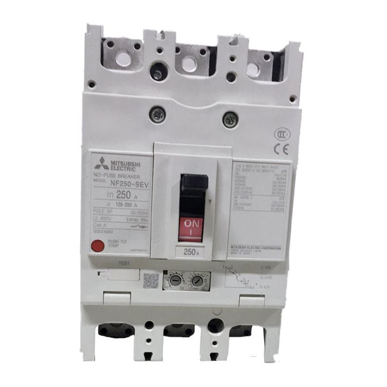
MDU BREAKER: MAIN UNIT
MODEL
NF250-SEV with MDU, NF250-HEV with MDU
NF400-SEW with MDU, NF400-HEW with MDU
NF800-SEW with MDU, NF800-HEW with MDU
INSTRUCTION MANUAL
● Read this Instruction Manual carefully prior to use, so that the product is used properly.
● After reading this manual, store it in a safe place so that it can be easily referenced when needed.
● Make sure that the end user receives this Instruction Manual.
Indications and what they mean are listed below.
Danger
Caution
MDU Breaker main unit
Securely insert the connection cable into the MDU connector (until the lock clicks into place). The product will be unable to measure
properly if the connection is poor.
Some models/specifications do not measure or display some items. These items and functions will be skipped.
Do not touch the terminal area. Doing so may cause an electrical shock.
Wrong handling may cause dangerous situation in which possibility of fatal accidents or serious injuries assumed.
Wrong handling may cause dangerous situation in which possibility of significant or minor injuries, or material damages assumed.
Using this under certain conditions may cause an electrical shock.
Connection cable
Caution
MDU
Danger
Connector
Table of Contents

Related Manuals for Mitsubishi Electric NF250-SEV


Summary of Contents for Mitsubishi Electric NF250-SEV
- Page 1 MDU BREAKER: MAIN UNIT MODEL NF250-SEV with MDU, NF250-HEV with MDU NF400-SEW with MDU, NF400-HEW with MDU NF800-SEW with MDU, NF800-HEW with MDU INSTRUCTION MANUAL ● Read this Instruction Manual carefully prior to use, so that the product is used properly.
-
Page 2: Table Of Contents
■ Table of Contents ………………………………………………………………………………………………………… 1. Safety Precautions ………………………………………………………………………………………………………… 2. Precautions for Use ……………………………………………………………………………………… 2.1 Standard operating conditions ………………………………………………………………………………………………… 2.2 Withstand voltage test …………………………………………………………………………………………… 2.3 Connection and Installation ……………………………………………………………………………………………………………………… 3. Requests ………………………………………………………………………………………………………… 3.1 Notes on Usage …………………………………………………………………… 4. Cautionary Instructions for Handling MDU Breaker ……………………………………………………………………………... -
Page 3: Safety Precautions
Unless otherwise noted, the following terms used in this Instruction Manual indicate the models shown below. 250 A frame 400 A frame 800 A frame NF250-SEV with MDU, NF400-SEW with MDU, NF800-SEW with MDU, Molded Case Circuit Breaker (MCCB) NF250-HEV with MDU... -
Page 4: Connection And Installation
(2) Mitsubishi Electric shall not be held responsible for damage caused for reasons not attributable to Mitsubishi Electric; opportunities or profit lost by customers caused by Mitsubishi Electric product failure; damage caused from extraordinary circumstances, secondary damage, accident compensation, damage to anything other than Mitsubishi Electric products, or compensation for any other work, whether foreseen or not by Mitsubishi Electric. -
Page 5: Cautionary Instructions For Handling Mdu Breaker
4. Cautionary Instructions for Handling MDU Breaker 4.1 Cautionary instructions for using MCCB Caution ● Electrical work must be performed by a qualified person (electrical worker). ● Maintenance and inspections must be conducted by someone with specialized knowledge. Turn the host circuit breaker OFF and confirm that no electricity is flowing. -
Page 6: Cautionary Instructions For Using Mdu Breaker With Pal Module (Optional) (Only For 250 A Frame)
4.3 Cautionary instructions for using MDU breaker with PAL module (Optional) (only for 250 A frame) Caution ● Cut OFF the control power before setting the pre-alarm pickup current. ● For the control power to the PAL module, refer to the table below. During the operation, set the voltage distortion to 10% or less. Control power supply Allowable voltage range Control VA... -
Page 7: Setting Method Of Overcurrent Tripping Characteristics
≤ 0.05N ・ m Ir (Step adjustable) Ii (Step adjustable) Model name NF250-SEV with MDU, NF250-HEV with MDU Rated current In (A) Current setting Ir (A) Variable from 125 to 250 (variable in 12.5-A steps) 2-3-4-5-6-8-10-12-14 × Rated current In Instantaneous pickup current Ii (A) 14 ×... - Page 8 2 400/800 A frame (1) Open the transparent cover. (2) Turn the dials to set the tripping characteristics. As shown in the figure below, use a screwdriver to turn the dials for setting tripping characteristics. Current setting 2 Current setting 1 (ln) Current setting 1 Short time delay (consecutive...
-
Page 9: Testing Method Of Overcurrent Trip
4.5 Testing method of overcurrent trip Test by using the "Y-351" breaker tester (option) or by energizing the MDU Breaker main unit. If using the "Y-351" breaker tester, follow the instructions in that product's Instruction Manual. Caution ● For the pre-alarm contact output for MCCB (with alarm contact attached [optional]), the MDU is connected to the MDU Breaker main unit and will not operate unless control power is applied to the MDU and the alarm contact output. - Page 10 2 400/800 A frame (1) Send AC power to the MDU Breaker main unit from a 3-phase power supply or 1-phase power supply. When using a 1-phase power supply, do so from two poles in series. Current adjustable resister Current adjustable resister (2) Each operating current can be confirmed by checking the LEDs on the front of the MDU Breaker main unit.
-
Page 11: Mdu Breaker Installation Procedure
5. MDU Breaker Installation Procedure Caution ● Turn the host circuit breaker OFF and confirm that no electricity is flowing. ● Set the MDU Breaker main unit to OFF or TRIP. ● If installing with connection cables attached to the MDU Breaker main unit, make sure that connection cables and connectors are not caught and damaged. - Page 12 (2) When external mounting type, screw the MDU mounting plate into the load side of the MDU Breaker main unit. (Figure 5 to 7) MDU Breaker main unit MDU mounting plate MDU mounting Fixing screw M3 × 10 plate (tightening torque: 1.0 to 1.1 N ・...
- Page 13 (3) When panel mounting type, leave some space (listed below) between the MDU Breaker main unit and MDU. [1] No transmission, with electric energy pulse output Model NF250-SEV with MDU 250 A frame NF250-HEV with MDU NF400-SEW 400 A with MDU...
-
Page 14: Alarm Contact Output (Optional)
6. Alarm Contact Output (Optional) Caution ● Note that alarm contact output will not operate unless control power is applied to the MDU and the alarm contact output. Refer to "MDU Breaker Instruction Manual: MDU" for details on operation. ● Alarm contact output is a factory installed option. It cannot be installed after. 6.1 Contact capacity and combinations for alarm contact output ●... - Page 15 +880-31-624-307 +880-28-321-791 +855-23-997-725 +56-32-2-320-600 +86-21-2322-3030 +86-755-2399-8272 +86-28-8446-8030 +57-4-4441284 +20-2-27961337 +30-211-1206-900 +91-124-4630300 +62-(0)21-6610651-9 +856-20-415899 +356(0)21-697-816 +95-(0)1-202589 +977-1-4411330 +47(0)55-506000 +92-(0)42-35752323 +92-(0)42-35753373 +92-(0)42-37631632 +63-(0)2-634-8691 +966-1-4770149 +65-6473-2308 +34(0)93-565-3131 +58-212-241-9952 +84-28-3910-5945 +84-24-3937-8075...
- Page 16 MDU Breakers Nov 2019 LN107A331H02 IB63E29-A 1911 ( MEE)...