Table of Contents

Related Manuals for Hitachi TransPortal


Summary of Contents for Hitachi TransPortal
- Page 1 SM 1H1.0002 1000 Technology Drive, Pittsburgh, PA 15219 645 Russell Street, Batesburg, SC 29006 TransPortal Interlock Monitor STS USA Part No. N37404000 SNMP-Based TransPortal Installation Operation Troubleshooting Copyright 2019 SM 1H1.0002 Rev. 2, March 2019...
- Page 2 TransPortalTM Interlock Monitor Copyright 2019 SM SM 1H1.0002 Rev. 2, March 2019...
- Page 3 TransPortalTM Interlock Monitor Proprietary Notice This document and its contents are the property of Hitachi Rail STS USA, Inc. (formerly known as Union Switch & Signal Inc., and hereinafter referred to as "STS USA"). This document is furnished to you on the following conditions: 1.) That no...
- Page 4 TransPortalTM Interlock Monitor Revision History REV. DATE NATURE OF REVISION July, 2009 Initial Release March 2019 Hitachi Rail STS Branding Copyright 2019 SM-1H1.0002 Rev. 2, March 2019...
-
Page 5: Table Of Contents
4.1. Configuring the M for Use with the TransPortal Interlock Monitor ......4-1 ICROLOK II 4.2. Configuring the TransPortal Interlock Monitor Operating Parameters ........4-2 4.2.1. Locally Accessing the Embedded Web Server ............. 4-2 4.2.2. Navigating the Embedded Web Server ................ 4-3 4.2.2.1. - Page 6 4.3.1. Generating the M Events File ..............4-13 ICROLOK II 4.3.2. Transferring the mlevents.txt File to the TransPortal Interface Monitor ..... 4-15 4.3.2.1. Using a Windows-Based Computer ............. 4-15 4.3.2.2. Using a Linux Computer................4-17 4.3.3. SNMP Trap Timestamp File ..................4-18 4.4.
- Page 7 TransPortalTM Interlock Monitor List of Figures Figure 2-1. TransPortal Interlock Monitor ................... 2-1 Figure 3-1. Typical Input/Output Connections ..................3-3 Figure 3-2. Typical Field Wiring ......................3-4 Figure 4-1. Typical M Settings and Configuration Servlet ..........4-1 ICROLOK II Figure 4-2.
- Page 8 TransPortalTM Interlock Monitor Copyright 2019 SM-1H1.0002 Rev. 2, March 2019...
-
Page 9: General Information
TransPortalTM Interlock Monitor GENERAL INFORMATION 1.1. Safety and Regulatory Information Read and thoroughly understand this manual before attempting any of the procedures listed. Pay particular attention to: CAUTION WARNING These headings may appear throughout this manual. Caution statements indicate conditions that could cause damage to equipment. Warning statements indicate conditions that could cause physical harm, serious injury, or loss of life. - Page 10 TransPortalTM Interlock Monitor Copyright 2019 SM-1H1.0002 Rev. 2, March 2019...
-
Page 11: Introduction
MLK) to view and react to these logged indications. Where timely access to remote MLK locations is not practical, the TIM may be used to TransPortal™ is a trademark of Hitachi Rail STS USA, Inc. ®... -
Page 12: Feature Overview
TransPortalTM Interlock Monitor monitor the MLK remotely and provide notification of these MLK events. This minimizes the need for travel to very remote sites. The TIM connects to the MLK using a serial interface. The TIM also connects to an SNMP host to deliver the events detected within the MLK. -
Page 13: Electrical And Mechanical Specifications
TransPortalTM Interlock Monitor 2.3. Electrical and Mechanical Specifications The TIM meets all applicable environmental, EMI, and vibration tolerance specifications for Class C equipment. Table 2-1 and Table 2-2 list the TIM specifications. Table 2-1. Operating Specifications PARAMETER VALUE System Power Source Voltages 8 to 30VDC, 10W Temperature Range –40 to +70°C... -
Page 14: Front Panel Inputs, Outputs, And Controls
TransPortalTM Interlock Monitor Capable of communicating over any type of public or private, wireless or wireless IP-based WAN, the TIM transmits SNMP-based Trap/Inform messages when any alarm situation is confirmed, and delivers periodic operating information and health check messages. SNMP-based TIM devices are configured to deliver SNMP Trap/Inform encoded alarm and status messages to properly configured SNMP host applications. -
Page 15: Power Input
TransPortalTM Interlock Monitor 2.5.4. Power Input The TIM is powered by 8–30VDC. Although the power input is fully isolated and protected against reverse battery connection, observe the polarity when connecting power to avoid damage to the unit. 2.6. Top Panel Keypad/Displays Due to the persisted IP network connection that the unit maintains, all monitored status, alarm information, and configuration settings can be managed over the network (Remote Operation). -
Page 16: System Status
TransPortalTM Interlock Monitor 2.6.2.4. System Status The System Status LED summarizes the health of the unit's internal operation. It is typically green, indicating that all systems are functioning nominally. If the System Status indicator turns red, it is a sign that one or more of the following conditions has been detected: •... -
Page 17: Installation And Setup
INSTALLATION AND SETUP This section provides detailed instructions for the proper installation and setup of the TransPortal Interface Monitor (TIM). Included are steps to perform the following: 1. Gather the tools and devices needed for installation. 2. Unpack and inspect the TIM. -
Page 18: Physical Mounting
18-inches away from high-voltage power sources or other equipment. The TransPortal should be mounted inside a separate, weatherproof enclosure (rated NEMA 4, 4X or better) if it is to be installed outdoors. 3.4. Connecting Field Wiring See Figure 3-1 for typical input/output connections and Figure 3-2 for typical field wiring. -
Page 19: Figure 3-1. Typical Input/Output Connections
TransPortalTM Interlock Monitor Figure 3-1. Typical Input/Output Connections Copyright 2019 SM-1H1.0002 Rev. 2, March 2019... -
Page 20: Figure 3-2. Typical Field Wiring
TransPortalTM Interlock Monitor Figure 3-2. Typical Field Wiring Copyright 2019 SM-1H1.0002 Rev. 2, March 2019... -
Page 21: Verifying Installation
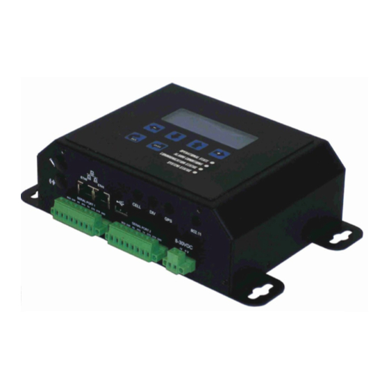
The TransPortal provides visual confirmation of connectivity and operation using a top panel backlit LCD display and bi-color LED status indicators. See Figure 2-1. 3.5.1. Initialization As the TransPortal powers up, the LCD top panel display typically shows the following; TransPortal Remote Monitoring Network Ansalso-STS USA Initializing…... -
Page 23: Configuring The Transportal Interlock Monitor
TransPortalTM Interlock Monitor CONFIGURING THE TRANSPORTAL INTERLOCK MONITOR This section provides detailed instructions for configuring the TransPortal Interlock Monitor (TIM) for operation. By this time, the unit is presumed to be physically installed, that a working network connection has been established, and that the unit has been turned on, initialized and is active. -
Page 24: Configuring The Transportal Interlock Monitor Operating Parameters
• Generate test trap – Button to generate and send a test trap to the SNMP manager. 4.2. Configuring the TransPortal Interlock Monitor Operating Parameters The embedded web server interface provides a full view of all conditions monitored by the MLK, and control over all configurable data fields that define the behavior of the TIM. -
Page 25: Navigating The Embedded Web Server
TransPortalTM Interlock Monitor 4.2.2. Navigating the Embedded Web Server The embedded web server has a number of navigational tabs along the top of the home page. Each tab takes you to a different web page, providing convenient local access to configure the behavior of the TIM. -
Page 26: Ethernet Tab
TransPortalTM Interlock Monitor 4.2.2.1. Ethernet Tab The Ethernet tab allows configuring Ethernet ports ETH0 and ETH1. See Figure 4-2 for typical screens and configuration data. Typically, ETH1 is used for connecting the TIM with the WAN and ETH0 is used for local access to the TIM using a laptop computer. To save configuration changes, select “Submit New Configuration”... - Page 27 TransPortalTM Interlock Monitor NOTE The data shown in these web page views are only representative of the configuration data required for a specific interlocking. Each TIM must be configured with interlocking-specific data for that location. Each TIM must also be configured with specific network- and SNMP-host interface parameters for that location.
-
Page 28: Networking Tab
TransPortalTM Interlock Monitor 4.2.2.2. Networking Tab The Networking tab allows opening up to five inbound ports, and enabling NAT and time synchronization. See Figure 4-3 and Figure 4-4 for typical screens and configuration data. To save configuration changes, select Submit New Configuration” before leaving the page. -
Page 29: Figure 4-4. Typical Networking Configuration Tab (2 Of 2)
TransPortalTM Interlock Monitor Figure 4-4. Typical Networking Configuration Tab (2 of 2) Copyright 2019 SM-1H1.0002 Rev. 2, March 2019... - Page 30 TransPortalTM Interlock Monitor NOTE The data shown in these web page views are only representative of the configuration data required for a specific interlocking. Each TIM must be configured with interlocking-specific data for that location. Each TIM must also be configured with specific network- and SNMP-host interface parameters for that location.
-
Page 31: Terminal Servers Tab
TransPortalTM Interlock Monitor 4.2.2.3. Terminal Servers Tab The Terminal Servers tab allows configuring a listening port for inbound TCP/IP connection, allowing network communication directly to a local serial port. See Figure 4-5 for a typical screen and configuration data. To save changes, select “Submit New Configuration”... - Page 32 TransPortalTM Interlock Monitor NOTE The data shown in these web page views are only representative of the configuration data required for a specific interlocking. Each TIM must be configured with interlocking-specific data for that location. Each TIM must also be configured with specific network- and SNMP-host interface parameters for that location.
- Page 33 TransPortalTM Interlock Monitor Buffer Size – Enter the maximum size (between 1 and 4095 bytes) allowed in the response to a network client. The actual number of bytes sent may be less if the Demark Timer expires before the serial butter is full. Enter 512 (typical) for this TIM application.
-
Page 34: Status Tab
TransPortalTM Interlock Monitor 4.2.2.4. Status Tab The Status tab shows the current status and configuration of the TIM. The data is shown for viewing only, and cannot be changed on this screen. See Figure 4-6 for a typical screen and configuration data. Figure 4-6. -
Page 35: Update Tab
TransPortalTM Interlock Monitor 4.2.2.5. Update Tab The Update tab allows updating the TIM firmware to a later version. See Figure 4-7 for a typical screen. Enter the Uniform Resource Locator (URL) from which an update file may be downloaded. This address must be accessible through one of the configured network interfaces of the TIM. -
Page 36: Figure 4-9. Typical Mlevents.xls File
TransPortalTM Interlock Monitor The MLK events file is generated using a supplied Microsoft Excel spreadsheet (mlevents.xls). The spreadsheet contains a list of every event of interest and the associated code, mask, description, reporting enable (“Y” for yes or “N” for no), SNMP OID, occurrence (number of times the event must occur), and period (time during which the specified number of event occurrences must occur) for each event to be reported. -
Page 37: Transferring The Mlevents.txt File To The Transportal Interface Monitor
TransPortalTM Interlock Monitor Figure 4-10. Typical mlevents.txt File 4.3.2. Transferring the mlevents.txt File to the TransPortal Interface Monitor The mlevents.txt file can be transferred to the TIM using either a Windows computer or a Linux computer. 4.3.2.1. Using a Windows-Based Computer For a windows-based computer, the simplest way to transfer the file to the TIM by using WinSCP (a free program available at http://winscp.net) as follows. -
Page 38: Figure 4-11. Typical Mlevents.txt File Transfer Login (Windows Computer)
TransPortalTM Interlock Monitor Figure 4-11. Typical mlevents.txt File Transfer Login (Windows Computer) 3. After WinSCP has logged into the TIM, the screen will be split into two. See Figure 4-12 for a typical split-screen display. Figure 4-12. Typical WinSCP Split Screen (Windows Computer) Copyright 2019 SM-1H1.0002 Rev. -
Page 39: Using A Linux Computer
TransPortalTM Interlock Monitor 4. Browse to the directory containing the new “mlevents.txt” file on the left, and “/home/microlok” directory on the right. See Figure 4-13 for a typical screen display. Figure 4-13. Typical mlevents.txt File Transfer (Windows Computer) 5. Drag the new “mlevents.txt” file to the right (TIM) window. This overwrites the existing mlevents.txt file in the TIM. -
Page 40: Snmp Trap Timestamp File
TIM). This manual does not cover detailed use of features typically available within the “Dev Tool.” 4.4.1. Locally at the TransPortal Interlock Monitor A communication port on the local computer must be configured to interface with Ethernet port ETH0 (typically) on the TIM. This is done using a serial-to-TCP/IP converter application (TCP-Com) included in the “Dev Tool”... -
Page 41: Configuring The Local Computer
TransPortalTM Interlock Monitor 4.4.1.1. Configuring the Local Computer NOTE The data shown in these web page views are only representative of the configuration data required for a specific interlocking. Each TIM must be configured with interlocking-specific data for that location. Each TIM must also be configured with specific network- and SNMP-host interface parameters for that location. -
Page 42: Figure 4-16. Typical Local Area Connection Properties (General)
TransPortalTM Interlock Monitor 2. Select “Properties,” enter the IP address data for Ethernet port ETH0 (typical) on the TIM, and select “OK.” See Figure 4-16. The IP address data shown is typical; enter the specific data for this TIM application. Figure 4-16. -
Page 43: Running The Microlok Ii Development System
TransPortalTM Interlock Monitor 4. Configure the converter, typically as shown in Figure 4-18 and Figure 4-19. The IP address data shown is typical; enter the specific data for this TIM application. Figure 4-18. Typical Serial-to-TCP/IP Converter Configuration Figure 4-19. Typical Serial-to-TCP/IP Converter I/O Options Configuration 4.4.1.2. -
Page 44: Figure 4-20. Typical Serial-To-Tcp/Ip Converter (Activated)
TransPortalTM Interlock Monitor 2. Open TCP-Com (See Figure 4-18.) and select “Activate.” See Figure 4-20. Figure 4-20. Typical Serial-to-TCP/IP Converter (Activated) 3. Launch the “Dev Tool” on the computer desktop. The communications pop-up will appear. See Figure 4-21. Figure 4-21. Typical M Development System Communications Pop-up ICROLOK II Copyright 2019... -
Page 45: Figure 4-22. Typical Microlok Ii Development System Communications Setup
TransPortalTM Interlock Monitor 4. Select the communication port activated in TCP-Com and enter the IP address of the Ethernet port (ETH0 typical) as the “Unit address.” See Figure 4-22. The address data shown is typical; enter the specific data for this TIM application. Figure 4-22. -
Page 46: Remotely From A Computer Network Workstation
TransPortalTM Interlock Monitor 6. Select the desired MLK unit to display the Main Menu for the unit. See Figure 4-24. Figure 4-24. Typical M Development System Main Menu ICROLOK II 4.4.2. Remotely from a Computer Network Workstation The M (MLK) Development System (“Dev Tool”) must be loaded onto the ICROLOK II workstation being used. -
Page 47: Figure 4-25. Typical Network Dashboard Screen
TransPortalTM Interlock Monitor Figure 4-25. Typical Network Dashboard Screen Copyright 2019 SM-1H1.0002 Rev. 2, March 2019 4-25... - Page 48 TransPortalTM Interlock Monitor Copyright 2019 SM-1H1.0002 Rev. 2, March 2019 4-26...
-
Page 49: Support And Maintenance
TransPortalTM Interlock Monitor SUPPORT AND MAINTENANCE There are no user serviceable parts or components in the TransPortal Interlock Monitor (TIM). The unit is shipped with an internal lithium battery enabled, supporting the unit's real time clock. While the battery-backed clock provides for faster unit startup, it is entirely optional for proper operation because the TIM has several means of obtaining the proper date and time for operation (i.e., over the network and using GPS, if so... - Page 50 TransPortalTM Interlock Monitor Copyright 2019 SM-1H1.0002 Rev. 2, March 2019...
-
Page 51: Glossary, Abbreviations, And Acronyms
CDMA Code Division Multiple Access, a cellular channel methodology, contrasted with GSM. CLASS C EQUIPMENT AREMA classification of the TransPortal device, used in protective bungalows or similarly NEMA-rated enclosures. Central Processing Unit, also microprocessor. DHCP Dynamic Host Configuration Protocol, a network... - Page 52 128-bit hash value data validation parameter that guarantees the authenticity of data, in this case used by the TransPortal event recorder to authenticate event data records. Mobile ID Number, the unique cellular address of a CDMA or GSM connected device.
- Page 53 –60dB (strong) and –100dB (weak). SD FLASH Secure Digital Flash (Memory), a non-volatile, non- battery backed solid state memory device used by the TransPortal for event recording. SERVLET A Java application that runs in a Web server or application server and provides server-side processing such as accessing a database and e-commerce transactions.
- Page 54 TransPortalTM Interlock Monitor End of Manual Copyright 2019 SM-1H1.0002 Rev. 2, March 2019...