YASKAWA YRC1000 Instructions Manual
Smart pendant
Hide thumbs
Also See for YRC1000:
- Instructions manual (454 pages) ,
- Operator's manual (198 pages) ,
- Startup manual (87 pages)
YRC1000/YRC1000micro
INSTRUCTIONS
FOR Smart Pendant
(JZRCR-APP30-1)
Upon receipt of the product and prior to initial operation, read these instructions thoroughly, and
retain for future reference.
MOTOMAN INSTRUCTIONS
YRC1000 INSTRUCTIONS
YRC1000 OPERATOR'S MANUAL (GENERAL) (SUBJECT SPECIFIC)
YRC1000 MAINTENANCE MANUAL
YRC1000 ALARM CODES (MAJOR ALARMS) (MINOR ALARMS)
YRC1000micro INSTRUCTIONS
YRC1000micro OPERATOR'S MANUAL
YRC1000micro MAINTENANCE MANUAL
YRC1000micro ALARM CODES (MAJOR ALARMS) (MINOR ALARMS)
YRC1000/YRC1000micro INSTRUCTIONS FOR Smart Pendant (JZRCR-APP30-1)
184775-1CD
5
MANUAL NO.
HW1485509
5
1 of 493
Chapters
Table of Contents

Related Manuals for YASKAWA YRC1000


Summary of Contents for YASKAWA YRC1000
- Page 1 MOTOMAN INSTRUCTIONS YRC1000 INSTRUCTIONS YRC1000 OPERATOR’S MANUAL (GENERAL) (SUBJECT SPECIFIC) YRC1000 MAINTENANCE MANUAL YRC1000 ALARM CODES (MAJOR ALARMS) (MINOR ALARMS) YRC1000micro INSTRUCTIONS YRC1000micro OPERATOR’S MANUAL YRC1000micro MAINTENANCE MANUAL YRC1000micro ALARM CODES (MAJOR ALARMS) (MINOR ALARMS) YRC1000/YRC1000micro INSTRUCTIONS FOR Smart Pendant (JZRCR-APP30-1) MANUAL NO.
- Page 2 • If your copy of the manual is damaged or lost, contact a YASKAWA Representative to order a new copy. Representatives are listed on the back cover. Be sure to tell the representative the manual number listed on the front cover.
- Page 3 HW1485509 Notes for Safe Operation Read this manual carefully before installation, operation, maintenance, or inspection of the YRC Controller. In this manual, the Notes for Safe Operation are classified as “DANGER”, “WARNING”, “CAUTION”, or “NOTICE”. Indicates an imminently hazardous DANGER situation which, if not avoided, may result in death or serious injury.
- Page 4 Immediately press the Emergency Stop button whenever there is a problem. The Emergency Stop buttons are located on the front panel of the YRC1000 (some models do not have this button) and on the top of the Smart Pendant.
-
Page 5
HW1485509
DANGER • Before operating the manipulator, make sure the servo power is turned OFF by performing the following operations. When the servo power is turned OFF, the SERVO ON LED on the Smart Pendant is turned OFF. – Press the Emergency Stop button on the top of the Smart Pendant or on the external control device, etc. -
Page 6
If the signal is input with the jumper cable connected, it does not function, which may result in personal injury or equipment damage.
WARNING • Perform the following inspection procedures prior to conducting manipulator teaching. - Page 7 HW1485509 General Safety on the Smart Pendant CAUTION • Be careful not to drop the Smart Pendant on the floor. • Pay attention to the handling of the cable so that it will not stumble on the Smart Pendant cable. •...
-
Page 8
Definition of Terms Used Often in This Manual
The MOTOMAN is the YASKAWA industrial robot product. The MOTOMAN Robot usually consists of the manipulator, the YRC1000 Controller, the Smart Pendant, and the manipulator cables. In this manual, the equipment is designated as follows:... -
Page 9
HW1485509 Descriptions of the Smart Pendant, buttons, and displays are shown as follows:
Equipment Manual Designation Smart Membrane Key The membrane keys are denoted with [ ]. Pendant ex. [JOG MODE] Jog Keys “Jog Keys” is generic names for the keys for jog operation. - Page 10 1.7.5 Touch Screen ..................... 1-10 1.7.6 Emergency Stop Button..................1-10 1.7.7 Emergency Stop Output ..................1-11 1.7.7.1 Emergency Stop Output for YRC1000 ..........1-11 1.7.7.2 Emergency Stop Output for YRC1000micro.......... 1-13 1.8 Smart Pendant Display ....................1-15 1.8.1 Job Layout ......................1-15 1.8.2...
-
Page 11: Changing Startup Security Level
HW1485509 Table of Contents 1.16 Mode..........................1-30 1.16.1 MANUAL (TEACH) Mode ................. 1-30 1.16.2 AUTOMATIC (PLAY) Mode................1-30 1.16.3 REMOTE Mode ....................1-30 1.17 Security Level Setting ....................1-31 1.17.1 Types of Security Level ..................1-31 1.17.2 Default Security Level Passcodes ..............1-33 1.17.3 Security Level Access Information .............. - Page 12 HW1485509 Table of Contents 2.4.8 Move to Position Panel ..................2-23 2.4.8.1 Joint Panel..................... 2-23 2.4.8.2 TCP Position Panel ................2-25 2.4.8.3 TCP Orientation Panel................2-26 3 Managing Jobs..........................3-1 3.1 Preparation for Teaching ....................3-1 3.1.1 Create New Job ....................3-1 3.1.1.1 Setting the Job Name................
- Page 13 HW1485509 Table of Contents 4.2 Checking a Step ......................4-11 4.2.1 GO TO POINT Operation ................... 4-11 4.2.2 Circular Movements with the GO TO POINT Operation........4-11 4.2.3 Spline Curve Movements with the GO TO POINT Operation......4-11 4.3 Test Job ........................... 4-12 4.3.1 Test Start ......................
- Page 14 HW1485509 Table of Contents 4.5.4 Direct Open......................4-41 4.5.4.1 User Variable..................4-41 4.5.4.2 Position Variable ................... 4-42 4.5.4.3 Input/Output Number Direct Open............4-43 4.5.4.4 Job Name Direct Open................4-43 4.6 User Variables ......................... 4-44 4.6.1 Setting Byte, Integer, Double, and Real Type Variables ........4-46 4.6.2 Setting String (Character) Type Variable............
- Page 15 HW1485509 Table of Contents 5.1.2 Test/Run Job Panel ....................5-3 5.1.2.1 Operation Buttons ................... 5-3 5.1.2.2 Operation Cycle ..................5-4 5.1.2.3 Playback Speed ..................5-4 5.1.2.4 Time Indicators..................5-5 5.2 Playback ..........................5-6 5.2.1 Playback Operation ....................5-6 5.2.1.1 Selecting the Start Mode ................. 5-6 5.2.1.2 Servo ON ....................
- Page 16 HW1485509 Table of Contents 6.3.2 Methods for User Frame Setting................. 6-22 6.3.3 User Frame Number ................... 6-22 6.3.4 User Frame Setting..................... 6-23 6.3.5 Deleting the User Frame..................6-25 6.4 Zones ..........................6-26 6.4.1 Cubic Zone ......................6-26 6.4.1.1 Cubic Zone Setting Operation ............... 6-27 6.4.2 Axis Zone......................
- Page 17 HW1485509 Table of Contents 7.4.2 I/O Windows ......................7-6 7.4.2.1 Smart Pendant I/O Configuration ............7-6 7.4.2.2 I/O Screens ..................... 7-6 7.5 I/O Detailed View ......................7-12 7.5.1 I/O Detailed View Overview................7-12 7.5.2 Editing Output Values..................7-23 7.6 EtherNet/IP Status Warning..................... 7-28 7.7 Block I/O ..........................
- Page 18 9.1.1 Soft Limits ......................9-2 9.1.2 Self-Interference ....................9-2 9.1.3 All Limits ....................... 9-2 9.2 Brake Release ........................9-3 9.2.1 Brake Release for YRC1000 ................9-3 9.2.2 Brake Release for YRC1000micro................ 9-4 9.2.3 Execute Brake Release ..................9-5 9.3 Backup and Restore ......................9-6 9.3.1 System Backup.....................
- Page 19 HW1485509 Table of Contents 9.4.4 Selection of Target/Source Folder..............9-14 9.4.4.1 Create a New Folder ................9-15 9.4.4.2 Rename an Existing Folder ..............9-16 9.4.4.3 Select the Target/Source Folder ............9-16 9.5 Robot Status Watch......................9-17 10 Direct Teach..........................10-1 10.1 Direct Teach Description ....................
- Page 20 HW1485509 Table of Contents 11.3.3.4 Edit Input Relays ................11-18 11.3.3.5 Edit Output Relays ................11-20 11.3.3.6 Add Relay ..................11-23 11.3.3.7 Delete Relay ..................11-24 11.3.3.8 Delete Line ..................11-25 11.3.3.9 Move Relay ..................11-25 11.3.3.10 Cancel Edit ..................11-25 11.3.3.11 Transferring and Updating Safety Logic Circuit File ......
- Page 21 HW1485509 Table of Contents 11.4.4 Robot Range Limit..................11-60 11.4.4.1 Condition Setting ................11-61 11.4.4.2 Confirming the Safety Range and Starting the Robot Range Limit ... 11-67 11.4.4.3 Switch the Monitoring Area ............... 11-69 11.4.4.4 Estimated CPU Load................. 11-71 11.4.5 Axis Range Limit..................... 11-72 11.4.5.1 Condition Setting ................
- Page 22 HW1485509 Table of Contents 11.7 Setting Example of the Safety Functions ..............11-106 11.7.1 Single Safety Laser Scanner to Pause Robot Motion........11-106 11.7.2 Single Safety Laser Scanner to Activate Collaborative Operation....11-109 11.7.3 Reduce the Robot Speed by Robot Position ..........11-111 11.7.4 Reduce the Robot Speed by Robot Position only when Collaborative Operation Mode............
- Page 23 15.2.4 User Alarm......................15-6 15.2.5 Notifications ...................... 15-6 16 Help / Support ..........................16-1 16.1 Take Screenshot......................16-1 16.2 YASKAWA Representative.................... 16-1 17 Maintenance ..........................17-1 17.1 Cleaning the Smart Pendant..................17-1 17.2 Cleaning the Smart Pendant Cable ................17-1 Appendix A ............................A-1...
-
Page 24: Smart Pendant
HW1485509 Smart Pendant General Product Description Smart Pendant General Product Description With this Smart Pendant, even users who have no experience of robot operation can easily perform teaching operation. Smart Pendant Contents Confirmation Confirm the contents of the delivery when the product arrives. •... - Page 25 * Two keys are shipped with the Smart Pendant. Cable Standard: 8 m Length maximum (optional): YRC1000 : 36 m (Standard 8 m + Extension 28 m) YRC1000micro: 20 m (Standard 8 m + Extension 12 m) Others USB connector (USB2.0) X 1 The software pendant installer built into the pendant can be downloaded to the USB memory and installed on the PC for use.
- Page 26 HW1485509 Smart Pendant Smart Pendant Overview Smart Pendant Overview Smart Pendant has several physical characteristics that a user will interact with. These are shown below: Fig. 1-1: Smart Pendant Overview (Front) Emergency Mode Switch Stop Bu on Status LED Touch Membrane Screen Keys...
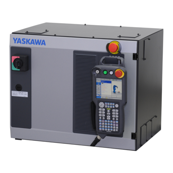
- Page 27 (some models do not have this button), and the Smart Pendant can be hung from a hook below the button. Fig. 1-4: YRC1000 Front View with Smart Pendant Emergency Stop...
- Page 28 HW1485509 Smart Pendant Connection of the Smart Pendant 1.5.2 Connecting to the YRC1000micro Connect the Smart Pendant cable to the connector (-X81) on the front panel of the YRC1000micro. Fig. 1-5: Connection of Smart Pendant Cable to the YRC1000micro If the Smart Pendant is not used, connect the Smart NOTE Pendant safety signal short circuit connector to connector (-X81).
- Page 29 HW1485509 Smart Pendant Holding the Smart Pendant Holding the Smart Pendant The Smart Pendant can be held in two ways: using the right hand, press the enable switch with the thumb or, using the left hand, press the enable switch with the index finger. Adjust the strip band to make the hand comfortable.
- Page 30 HW1485509 Smart Pendant Display and Operating Elements Display and Operating Elements Operating elements include: – Status LED – Membrane keypads – Enable switch – Mode key – Touch screen – Emergency Stop button 1.7.1 Status LED The status LEDs are found on the top right side of the Smart Pendant. POWER: indicates the power status of the Smart Pendant.
- Page 31 HW1485509 Smart Pendant Display and Operating Elements – GO TO POINT When the [GO TO POINT] is pressed and a motion instruction is selected in the Job Contents view, the manipulator moves to the selected position. Only available in MANUAL (TEACH) mode.
- Page 32 HW1485509 Smart Pendant Display and Operating Elements – JOG MODE Selects the operation coordinate system when the manipulator is manually operated. • The coordinate system can be selected from the four coordinate systems: Joint, XYZ- World, XYZ-Tool, and XYZ-User. • Each time this key is pressed, the coordinate system is switched in the following order: Joint ...
- Page 33 HW1485509 Smart Pendant Display and Operating Elements 1.7.4 Mode Switch Mode switch is used for toggling between MANUAL (TEACH) mode, AUTOMATIC (PLAY) mode, and REMOTE Mode. – MANUAL (TEACH) mode Axis can be operated. Job and other settings can be edited using the Smart Pendant.
- Page 34 (some models do not have this button). These contact outputs are always valid regardless of the YRC1000 main power supply status ON or OFF (Status output signal: normally closed contact). These outputs are dual output.
- Page 35 HW1485509 Smart Pendant Display and Operating Elements Fig. 1-9: Emergency Stop Output Circuit for YRC1000 YRC1000 Front door of YRC1000 Emergency Safety circuit board Safety terminal block board Stop button (JANCD-ASF01-E) (IM-YE250/5-80P) CN206 ESPOUT1- ESPOUT2- ESPOUT1+ ESPOUT2+ If contact output that interlocks with the Emergency Stop button on the Smart Pendant it is necessary, refer to “YRC1000 INSTRUCTION (RE-CTO-A221)”...
- Page 36 HW1485509 Smart Pendant Display and Operating Elements 1.7.7.2 Emergency Stop Output for YRC1000micro When using the Smart Pendant, it does not interlock with the Emergency Stop button of the Smart Pendant. The contact Close status is output at all times. These outputs are dual output.
- Page 37 HW1485509 Smart Pendant Display and Operating Elements If contact output that interface with the Emergency Stop button of the Smart Pendant is necessary, refer to “YRC1000micro INSTRUCTION (RE-CTO-A222)” for the section on “Safety Logic Circuit”. PPESP signal, and other signals can be combined and output to the functional safety board’s general purpose outputs (FSBOUT 18).
- Page 38 HW1485509 Smart Pendant Smart Pendant Display Smart Pendant Display The Smart Pendant Display is a 10-inch color Touch Screen Display. The layout of each screen is different; however, there are two main screen layouts that will be described in this section: –...
- Page 39 HW1485509 Smart Pendant Smart Pendant Display Fig. 1-11: Job Layout 1.8.2 Configuration Layout The screen is displayed in configuration layout when viewing or editing a setting (e.g. Tool, User Frame). The screen is divided into four main display areas: Status Bar View status and access common actions such as Main Menu and Servo ON/OFF.
- Page 40 HW1485509 Smart Pendant Smart Pendant Display Fig. 1-12: Configuration Layout HW1485509 1-17 40 of 493...
- Page 41 HW1485509 Smart Pendant Smart Pendant Display 1.8.3 Help Information Smart Pendant also has built-in Help Information to further describe the interfaces. This information can be accessed by pressing the icon that shows up on many pages. This will open a pop-up window with more information that can be dismissed by either pressing the X or by pressing outside the pop-up window.
- Page 42 YRC Controller incompatibility, an {Export Logs...} will appear. This button can be used to save internal logs to a USB storage device to aid troubleshooting by a YASKAWA Representative. The MODE switch will not work during Smart Pendant startup.
- Page 43 HW1485509 Smart Pendant 1.10 Home Screen 1.10 Home Screen When the YRC Controller boots up, the Home Screen displays. Fig. 1-15: Home Screen HW1485509 1-20 43 of 493...
- Page 44 HW1485509 Smart Pendant 1.10 Home Screen The home screen contains short-cuts to three common actions for the manipulator: Use this button to view the Current Job (i.e. last Job opened) for editing/programming. To use this function, the Key Switch must be switched to the MANUAL (TEACH) position.
- Page 45 Contains sub-items such as {Limits Release}, {Brake Release}, {Force/Torque Watch} and {File Transfer} Alarms Shows the Alarm History and Alarm Descriptions System Settings Contains sub-items of {General} and {Network} Help / Support Contains a YASKAWA contact list, and screenshot HW1485509 1-22 45 of 493...
- Page 46 HW1485509 Smart Pendant 1.12 Status Bar 1.12 Status Bar The Status Bar shows the YRC Controller status. The following configuration can be accessed from the Status Bar: Menu Use this button to access the menu. Tool Number Use this control to change the current Active Tool in MANUAL (TEACH) mode.
- Page 47 Emergency Stop – Displays when the EMERGENCY STOP button (i.e. on Smart Pendant, YRC1000 remote button) is pressed. Protection Stop by PFL Function – Only for the manipulator that has PFL function which enables the human collaborative operation.
- Page 48 YRC Controller has active alarms. Low Battery – This alerts the user to a lower battery condition of the YRC Controller CPU battery. Contact a YASKAWA representative when this occurs. Messages – shows the number of messages when the YRC Controller has active messages...
- Page 49 HW1485509 Smart Pendant 1.13 Character Input Operation 1.13 Character Input Operation Tap on the data or text for which characters are to be input and the software keypad will be displayed. 1.13.1 Character Input There are two types of software keypads: alphanumeric keypads and symbol keypads.
- Page 50 HW1485509 Smart Pendant 1.13 Character Input Operation 1.13.2 Alphanumeric Input Number input is performed with the Numeric Value Keypad or on the alphanumeric input keypad. Numbers include 0 to 9, the decimal point (.), the minus sign/hyphen (-), and the hash sign (#). Tap the desired character and tap {Enter} to enter the character.
- Page 51 HW1485509 Smart Pendant 1.14 Numeric Value Input Operation 1.14 Numeric Value Input Operation Press the numeric value input area to display the numeric value keypad. Fig. 1-20: Keypad for Numeric Value Keypad Key on the Smart Description Pendant Cancel Clears all the characters being typed and closes the numeric value keypad Clear...
- Page 52 HW1485509 Smart Pendant 1.15 Language Setting 1.15 Language Setting Two languages can be displayed alternately. 1. Go to {HOME} {System Setting} {General} 2. Select the language from the pull-down list. The available languages are: – English – Japanese Fig.
- Page 53 HW1485509 Smart Pendant 1.16 Mode 1.16 Mode Three mode selections determine control of the manipulator system. These modes are MANUAL (TEACH), AUTOMATIC (PLAY) and REMOTE. Traditionally, MANUAL is also called TEACH, and AUTOMATIC is also called PLAY. 1.16.1 MANUAL (TEACH) Mode In MANUAL (TEACH) mode, the following actions can be performed: –...
-
Page 54: Security Level Setting
YASKAWA representative. The YRC Controller serial number is required to generate a valid one-time passcode, which displays on the Security Access Popup window. This access is to be used by a YASKAWA representative. Once accessed, HW1485509 1-31... - Page 55 HW1485509 Smart Pendant 1.17 Security Level Setting Support access will persist until the Smart Pendant or YRC Controller is restarted. Fig. 1-22: Security Support Access HW1485509 1-32 55 of 493...
- Page 56 HW1485509 Smart Pendant 1.17 Security Level Setting 1.17.2 Default Security Level Passcodes Operation in Edit, Management, and Safety level require a passcode. The default passcodes for each security level are: – Editing: 000000000000000 (all 0s' - 16 digits) – Managing: 9999999999999999 (all 9s' - 16 digits) –...
- Page 57 HW1485509 Smart Pendant 1.17 Security Level Setting 1.17.4 Selecting Security Level 1. Go to {Security: ---} under the {MENU}. 2. Select the desired Security Access Level from {OPERATION}, {EDIT}, {MANAGEMENT}, or {SAFETY}. 3. Insert passcode, if required. – Switching to a lower level access does not require inserting a passcode.
-
Page 58: Operate In Management Level Or Higher
HW1485509 Smart Pendant 1.17 Security Level Setting 1.17.5 Security Level Settings 1.17.5.1 Changing Passcode The passcode for Edit and Management level can be changed. The passcode for Safety Level must be changed using Software Pendant (refer to chapter 12 “Software Pendant” ). 1. -
Page 59: Table Of Contents
HW1485509 Smart Pendant 1.17 Security Level Setting 1.17.5.2 Changing Startup Security Level The Security Level at startup/restart can be set to Operation, Edit or Management level. 1. Operate in Management Level or higher. 2. Go to {MENU} {System Settings} {General} 3. - Page 60 HW1485509 Manipulator Coordinate Systems and Operations Control Groups and Coordinate System Manipulator Coordinate Systems and Operations Control Groups and Coordinate System 2.1.1 Control Group For the YRC Controller, a group of axes to be controlled is called a “Control Group”. The Control Group is split into two units: –...
- Page 61 HW1485509 Manipulator Coordinate Systems and Operations Control Groups and Coordinate System 2.1.2 Types of Coordinate System The following coordinate systems are used to operate the manipulator. Type Description Joint Coordinate Allows user to move each joint axis independently. XYZ - World Coordinate Allows user to move the manipulator in Cartesian directions relative to the manipulator base.
- Page 62 HW1485509 Manipulator Coordinate Systems and Operations General Operations General Operations 2.2.1 Check Safety Before operating the YRC Controller, read chapter 1 “Safety” of the INSTRUCTIONS of the YRC Controller. Always use caution around the manipulator system and peripherals. 2.2.2 Select Operation Mode Set the mode switch on the Smart Pendant to “MANUAL (TEACH)”.
- Page 63 HW1485509 Manipulator Coordinate Systems and Operations General Operations 2.2.5 Servo ON Before the manipulator can be moved in MANUAL (TEACH) mode or AUTOMATIC (PLAY) mode, the servos must be turned ON. This can be accomplished by: – Pressing the {SERVO} on the Status Bar –...
- Page 64 – The {SERVO} turns orange when the servo power supply is turned 2. Press Emergency Stop button. – The Emergency Stop button is on the YRC1000 (some models do not have this button) or the Smart Pendant. 3. Confirm servo power is turned OFF –...
- Page 65 HW1485509 Manipulator Coordinate Systems and Operations Coordinate Frames and Manipulator Jogging Coordinate Frames and Manipulator Jogging A manipulator can be jogged in MANUAL (TEACH) mode using different methods supported by the Smart Pendant. The various jogging modes can be selected using three different controls: –...
- Page 66 HW1485509 Manipulator Coordinate Systems and Operations Coordinate Frames and Manipulator Jogging All jogging modes have the following items in common on the Robot Jog panel. Fig. 2-3: Common Items on Robot Jog Panel (Top) Jogging Mode – Control for selecting jogging mode (MANUAL (TEACH) mode). Jog Speed –...
- Page 67 HW1485509 Manipulator Coordinate Systems and Operations Coordinate Frames and Manipulator Jogging 2.4.1 Smart Frame Mode WARNING Use of Smart Pendant in an area with strong geomagnetic disturbance or around metal objects (such as wire fences or steel frames) may result in manipulator motion directions not matching Smart Frame jogging directions.
- Page 68 HW1485509 Manipulator Coordinate Systems and Operations Coordinate Frames and Manipulator Jogging Fig. 2-5: Smart Frame Orientation Table 2-1: Smart Frame Tool Buttons Tool Button Description Move robot TCP in +Z direction with respect to Tool Frame Move robot TCP in -Z direction with respect to Tool Frame Rotate robot TCP around +Z Tool Frame axis (+Rz) Rotate robot TCP around -Z Tool Frame axis (-Rz) The Robot/Tool Toggle button in the middle of the screen can be used to...
- Page 69 HW1485509 Manipulator Coordinate Systems and Operations Coordinate Frames and Manipulator Jogging Fig. 2-6: Robot/Tool Toggle Additionally, the membrane [Jog Keys] can be used for Joint Axis jogging in Smart Frame Mode. Each time the YRC Controller is turned off, Smart Frame will lose its calibration.
- Page 70 HW1485509 Manipulator Coordinate Systems and Operations Coordinate Frames and Manipulator Jogging Fig. 2-7: Standing Position and Operation Direction The front of the Manipulator can be easily identified as the face of the Manipulator base that is on the opposite side of the cable connectors on the Manipulator base.
- Page 71 HW1485509 Manipulator Coordinate Systems and Operations Coordinate Frames and Manipulator Jogging The robot can be in any position for sensor calibration. 1. Hold the Smart Pendant and stand facing the front of the robot. – The top edge of the Smart Pendant must be held parallel to the base of the manipulator.
- Page 72 HW1485509 Manipulator Coordinate Systems and Operations Coordinate Frames and Manipulator Jogging 2.4.2 Joint Mode When the manipulator is operating in Joint Mode, each axis of the manipulator can be moved independently. Axis Operation in Joint Mode When two or more [Jog Keys] are pressed at the same time on the membrane key, the manipulator performs a combined movement.
- Page 73 HW1485509 Manipulator Coordinate Systems and Operations Coordinate Frames and Manipulator Jogging 2.4.3 XYZ – World Mode In the XYZ – World mode, the manipulator moves parallel to the X, Y, or Z axes defined with respect to the manipulator base. Axis Operation in XYZ –...
- Page 74 HW1485509 Manipulator Coordinate Systems and Operations Coordinate Frames and Manipulator Jogging 2.4.4 XYZ - Tool Mode In XYZ – Tool mode, the manipulator moves parallel to the X-, Y-, and Z- axes defined with respect to the tip of the tool. Axis Operation in the XYZ - Tool Mode When two or more [Jog Keys] are pressed at the same time on the membrane key, the manipulator performs a combined...
- Page 75 HW1485509 Manipulator Coordinate Systems and Operations Coordinate Frames and Manipulator Jogging In tool coordinates, the manipulator can be moved using the effective tool direction as a reference, regardless of the manipulator’s position or orientation. These motions are best suited for moving the manipulator parallel to the tool frame while maintaining tool orientation with respect to the workpiece.
- Page 76 HW1485509 Manipulator Coordinate Systems and Operations Coordinate Frames and Manipulator Jogging 2.4.5 XYZ - User Frame Mode In XYZ – User Frame mode, the manipulator moves parallel to each axis of the user-defined coordinates. A user-specified coordinate frame is typically attached to an object such as a work surface, pallet, or conveyor. The user defines the X, Y, and Z axes with the desired slopes and positions available within the manipulator’s motion range.
- Page 77 HW1485509 Manipulator Coordinate Systems and Operations Coordinate Frames and Manipulator Jogging 2.4.6 Hand Guiding Mode Hand Guiding mode can be used on manipulators that have the PFL (Power and Force Limiting) function for human collaborative operation (ex. MOTOMAN-HC10) only. In this mode, the user can directly position the Manipulator by physically moving the arm by hand.
- Page 78 HW1485509 Manipulator Coordinate Systems and Operations Coordinate Frames and Manipulator Jogging 2.4.6.1 ALL JOINTS In this mode, all axes of the robot can be guided by hand. This mode is most useful for large motions and recovering from faults / collisions. Fig.
- Page 79 HW1485509 Manipulator Coordinate Systems and Operations Coordinate Frames and Manipulator Jogging 2.4.6.3 XYZ + TOOL In this mode, the robot can be guided in the X, Y, Z directions by hand. This is the most useful mode for teaching robot positions. The tool axis of the robot (T-axis) can also be rotated to orient the tool.
- Page 80 HW1485509 Manipulator Coordinate Systems and Operations Coordinate Frames and Manipulator Jogging 2.4.7 Motion at Robot TCP For motion at the TCP (Tool Center Point), the manipulator’s posture can be modified without changing the position of the tool’s tip (TCP). The motion at TCP is available in the World Coordinate Frame, Tool Coordinate Frame, and User Coordinate Frame.
- Page 81 HW1485509 Manipulator Coordinate Systems and Operations Coordinate Frames and Manipulator Jogging – In Tool Frame, wrist axis rotations are based on the X, Y, and Z axes of the tool coordinates. X-axis Z-axis Y-axis – In User Frame, wrist axis rotations are based on the X, Y, and Z axes of the user coordinates.
- Page 82 HW1485509 Manipulator Coordinate Systems and Operations Coordinate Frames and Manipulator Jogging 2.4.8 Move to Position Panel The Move to Position Panel is a utility that can be used to more precisely position a robot while jogging. This feature will let the user enter the desired position and jog directly to the entered coordinates as well as “snapping”...
- Page 83 HW1485509 Manipulator Coordinate Systems and Operations Coordinate Frames and Manipulator Jogging Fig. 2-20: Joint Position Panel Current Axis Position display Target Position Selection/Display - By default, this value is the “User Target” which allows for entering custom positions. The drop-down selection contains standard robot configurations such as Work Home and Robot Position Confirmation.
- Page 84 HW1485509 Manipulator Coordinate Systems and Operations Coordinate Frames and Manipulator Jogging 2.4.8.2 TCP Position Panel The TCP Position Panel can be used whenever the Jogging Mode is set to XYZ-World, XYZ-User, or XYZ-Tool. To open it, press any of the TCP XYZ positions on the screen: Fig.
- Page 85 HW1485509 Manipulator Coordinate Systems and Operations Coordinate Frames and Manipulator Jogging 2.4.8.3 TCP Orientation Panel The TCP Orientation Panel is used whenever the Jogging Mode is set to XYZ-World, XYZ-User, or XYZ-Tool. To open the TCP Orientation Panel, press any of the TCP Rx, Ry, or Rz positions on the screen. Fig.
- Page 86 HW1485509 Manipulator Coordinate Systems and Operations Coordinate Frames and Manipulator Jogging Move to Position button - This moves the robot towards the target Rx, Ry, Rz positions. These buttons will have an orange boarder if any the Current Rx, Ry, Rz positions do not match the target positions. HW1485509 2-27 86 of 493...
- Page 87 HW1485509 Managing Jobs Preparation for Teaching Managing Jobs This section explains how to manage jobs without moving the manipulator. Copying, deleting, and modifying jobs can only be done in MANUAL (TEACH) mode. Edit operations on a job are restricted if an edit lock is NOTE applied to the job.
- Page 88 HW1485509 Managing Jobs Preparation for Teaching 3.1.1.1 Setting the Job Name The following rules apply to the job name: – 1 to 32 alphanumeric characters can be used. – Job names may be written with numerals only. – Only upper-case letters can be used for alphabets. –...
- Page 89 HW1485509 Managing Jobs Preparation for Teaching 3.1.1.3 Setting the Comment Comments are a means to provide description about the Job’s purpose. Constraints on comment are: – 0 to 32 alphanumeric and symbol characters can be used. – Symbols that are not grayed out can be used. 1.
- Page 90 HW1485509 Managing Jobs Job List Job List 3.2.1 Default Job and Current Job In the Job List, there are two specially designated jobs: – Default Job The job designated as the default job can be opened and executed from external I/O signals. It is designated with a green “Check Mark”...
- Page 91 HW1485509 Managing Jobs Job List 3.2.2 Sorting Job In the Job List, jobs can be sorted according to: • Job Name • Tag • Edited date To sort items, press the title of the item and the sorting order symbol will appear.
- Page 92 HW1485509 Managing Jobs Copying Jobs Copying Jobs This operation is used to copy existing jobs, which are then used to create new jobs. It can be performed in the Job List. On the Job List, select the job to be copied from the list. 1.
- Page 93 HW1485509 Managing Jobs Deleting Jobs Deleting Jobs This operation is used to delete jobs from the YRC Controller. It can be performed from the Job List. From the Job List, select the job to be deleted from the list of registered jobs.
- Page 94 HW1485509 Managing Jobs Modifying Job Modifying Job This operation is performed to modify a job that has already been created. The operation is performed from the Job List. From the Job List, select the job to be modified. 1. Select {Job List} under {MENU}. –...
- Page 95 HW1485509 Managing Jobs Modifying Job 3.5.1 Modifying Job Names 1. Tap on the Job Name. Fig. 3-5: Modifying Job Names 2. Edit using the alphanumeric keypad. 3. Press {Enter} on the keypad. For detail on Job Names, refer to chapter 3.1.1.1 “Setting the Job Name”. 3.5.2 Modifying Tag 1.
- Page 96 HW1485509 Managing Jobs Modifying Job 3.5.3 Modifying Comment 1. Tap on the Comment Fig. 3-7: Modifying Comment 2. Edit using the entry popup. 3. Press {Enter} on the keypad. For details on Comment, refer to chapter 3.1.1.3 “Setting the Comment”. 3.5.4 Setting Default Job The Default Job is a job specially designated so that can be triggered by an external I/O signal.
- Page 97 HW1485509 Managing Jobs Modifying Job 3.5.5 Setting Edit Lock The Edit Lock function is used to prevent accidental editing of the Job Contents or its name, tag or comments. Attempting to edit a job when “Lock the Job” is checked will result in a notice asking to unlock the Job. The Edit Lock function can be used in Management Level or higher.
- Page 98 HW1485509 Managing Jobs Additional Settings Additional Settings The Additional Settings can be accessed from Job Details panel. Refer to chapter 4.8 “Local Variables” and chapter 4.9 “Teaching Coordinate” for more information. HW1485509 3-12 98 of 493...
- Page 99 Additional items: Speed and time are set depending on the type of instruction. When required, numerical or character data is added to the condition-setting tags. For a full list of supported instructions and parameters, refer to YRC1000/YRC1000micro SUPPLEMENTAL INSTRUCTIONS FOR Smart Pendant (INSTRUCTIONS FOR INFORM LANGUAGE) (HW1485511).
- Page 100 HW1485509 Teaching Teaching Operation 4.1.2 Jogging the Robot for Teaching Before teaching and recording a Robot motion in the INFORM job, the Robot needs to be moved to the position of interest. This motion is manually performed by the operator using any of the methods described in chapter 2.4 “Coordinate Frames and Manipulator Jogging”.
- Page 101 (P4) at a connecting point of the preceding movement and the following movement. However, when steps at the same connecting point are taught, movements cannot be continuously performed. For more information on the “FPT” tag, refer to YRC1000/YRC1000micro SUPPLEMENTAL INSTRUCTIONS FOR Smart Pendant (INSTRUCTIONS FOR INFORM LANGUAGE) (HW1485511).
-
Page 102
HW1485509 Teaching Teaching Operation Table 4-3: Interpolation Type for Continuous Circle Curve Point Interpolation Instruction Type Joint or JointMove Linear LinearMove Joint or linear Circular CircleMove motion type Joint or JointMove Linear LinearMove Circular CircleMove Joint or JointMove Linear LinearMove
... - Page 103 HW1485509 Teaching Teaching Operation Continuous Spline Curves This describes a manipulator moving through a path created by combining parabolic curves. This differs from circular interpolation in that steps at an identical point or an FPT tag are not required at the connecting point between two spline curves.
- Page 104 HW1485509 Teaching Teaching Operation 4.1.4 Teaching Steps There are two basic teaching steps for the manipulator: move or stop. The following sections describe the method of how to teach Motion Instruction and Timer in the job. 4.1.4.1 Teaching Motion Instructions Whenever one step is taught, a motion instruction is inserted.
- Page 105 HW1485509 Teaching Teaching Operation Selecting the Tool Number 1. Before teaching the position, press the {Tool} text. Tool setting needs to be completed in advance. For tool setting instruction, refer to chapter 6.1 “Tool Settings”. 2. Select the Active Tool from the list and press {Select}. Setting the Interpolation Type ...
- Page 106 HW1485509 Teaching Teaching Operation 2. Insert the desired speed and press {SAVE}. – If an entered value is outside the allowable range, the input value will be replaced to with the nearest value within the allowable range. 3. The speed is now registered. 4.1.4.2 Setting Timer Instruction The timer instruction function stops the manipulator for a specified length of time.
- Page 107 HW1485509 Teaching Teaching Operation 4.1.5 Overlapping: The First and Last Steps Why is overlapping the first and last step necessary? Assume that the job shown below is to be repeated. The manipulator moves from the last step (Step 6) to the first step (Step 1).
- Page 108 HW1485509 Teaching Teaching Operation 6. Press {RE-TEACH} – The position data for the first step is registered on the last step. – This changes the position data in the last step ONLY. Interpolation type and play speed will not change. HW1485509 4-10 108 of 493...
- Page 109 HW1485509 Teaching Checking a Step Checking a Step 4.2.1 GO TO POINT Operation To check the position of a taught reference point, move the manipulator to the reference point with the {GO TO POINT}. CAUTION • For safety, set jogging speed at Mid or below. Refer to chapter 2.2.4 “Select Jogging Speed”...
- Page 110 HW1485509 Teaching Test Job Test Job Playback operations can be tested and verified in MANUAL (TEACH) mode. 1. Place operations in MANUAL (TEACH) mode. 2. Open the job from the {Job List} under {MENU}. 3. Go to {TEST/RUN JOB} from the Navigation Bar. HW1485509 4-12 110 of 493...
- Page 111 HW1485509 Teaching Test Job 4.3.1 Test Start Test Start simulates playback operation in MANUAL (TEACH) mode. This function is convenient for verifying operation instructions and motions, helping to achieve continuous paths. Test operation differs in the following ways from actual playback in the AUTOMATIC (PLAY) mode: –...
- Page 112 HW1485509 Teaching Test Job 4. Press and hold {TEST START}. – The speed of the motion will be limited to 250 mm/sec. – Job execution will start from the selected line. To run the job in full speed, switch to the AUTOMATIC NOTE (PLAY) position and press the {RUN}.
- Page 113 HW1485509 Teaching Commands Commands 4.4.1 Command Group The commands are divided into five groups by processing or each work. Display Content Example General General commands to the job Timer, Comment Motion Moves the manipulator JointMove, LinearMove Controls input and output DigitalOut, PulseOut Math Performs arithmetic calculation...
- Page 114 HW1485509 Teaching Commands 4.4.2 Color Coordinates There are nine colors displayed in Job Contents view. Table 4-6: Color Coordinates Color Item Pink General Commands Orange Motion Commands I/O Commands Dark Blue Operating Commands Light Blue Control Commands Purple Variables Green Comment Brown Macro...
- Page 115 HW1485509 Teaching Commands 4.4.4 Editing Commands Move the cursor to the command to be edited, in the MANUAL (TEACH) mode. (1) Changing numeric data Select the highlighted item on the instruction. Input the value using the numeric keypad. III) Press {SAVE} to register the edit. (2) Adding, modifying, or deleting an additional item Press Detail Edit icon on the right side of the Job Contents view.
- Page 116 HW1485509 Teaching Commands Modifying Position There are two methods for modifying (i.e. re-teaching) a position. (1) Modifying from Job Contents View The {RE-TEACH} inside the Job Contents View is visible when selecting a motion instruction. When pressing this button, the selected line blinks indicating the position is re-taught.
- Page 117 HW1485509 Teaching Commands The tool number is seen in the box. The tool number cannot NOTE be edited, because the TCP may change when changing the tool. To change the tool number teach a new step. Modifying Motion Type A motion instruction can be changed between all types (JointMove, LinearMove, CircleMove, SplineMove) from the Job Contents view or from the Detail Edit panel.
- Page 118 HW1485509 Teaching Commands (2) Modifying from Detail Edit Panel 1. Select the motion instruction and open Detail Edit panel 2. Select the “Motion Type” parameter 3. Select the desired Motion Type from the list HW1485509 4-20 118 of 493...
- Page 119 HW1485509 Teaching Commands Modifying Speed 1. Select the Speed. The number that can be entered are different among interpolation type. • Joint mode: specifies the Joint Speed, which is shown as a percentage of the Robot’s highest speed. Speed: 0.01% to 100% •...
- Page 120 HW1485509 Teaching Commands 2b. For Variable, select the variable type from Byte, Integer, and Double type, and its number on the numeric keypad. Variable's content can be browsed from the {Browse Variable}. When the variable is used for speed with a LinearMove instruction, the unit is 0.1mm/s.
- Page 121 HW1485509 Teaching Commands 2c. For Local Variable, select the variable type and enter its number on the numeric keypad. Local Variable types will only be available if they have been NOTE allocated for the job. For more information on Local Variables, refer to chapter 4.8 “Local Variables”.
- Page 122 HW1485509 Teaching Commands The relationship between path and accuracy for position levels is as follows. Fig. 4-5: Position Level Position Levels Accuracy Teaching position Position level 0 Fine Rough Position level 1 Position level 2 Position level 3 Position level 4 Positioning level 8 1.
- Page 123 HW1485509 Teaching Commands 2b. For Variable, select the variable type from Byte, Integer, and Double type, and its number on the numeric keypad. The variable's content can be browsed from the {Browse Variable}. For array variables, refer to chapter 4.6 “User Variables”. HW1485509 4-25 123 of 493...
- Page 124 HW1485509 Teaching Commands 2c. For Local Variable, select the variable type and enter its number on the numeric keypad. Local Variable types will only be available if they have been NOTE allocated for the job. For more information on Local Variables, refer to chapter 4.8 “Local Variables”.
- Page 125 HW1485509 Teaching Commands 4.4.5 Favorites Frequently used commands can be saved to {Favorites} for quick access. To access favorites, open the {Favorites} tab in the command group. There is no limit on the amount of commands to save in {Favorites}. 1.
- Page 126 HW1485509 Teaching Commands 4.4.6 Command Builder Command Builder is used to add basic commands to a job. Command Builder uses simple instructions to support ease of use for users. Command Builder can be used to add three basic types of command: –...
- Page 127 HW1485509 Teaching Commands Command Builder limits the number of variables, I/O, etc. that can be modified. However, the commands generated by Command Builder can be modified in the Job Contents view to use any variable and I/O. 6. The added command is displayed in the Job Contents view. Press the {Detail Edit} icon to the right of the added line.
- Page 128 HW1485509 Teaching Commands 4.4.7 Expanded Inform Line In cases where an instruction has more parameters than can be displayed in one line, an arrow indicator displays. To view all of the parameters, press the arrow to expand the Inform line and press again to minimize the Inform line.
- Page 129 HW1485509 Teaching Editing Job Editing Job The Job Content Header provides access to three menus that make it easier to quickly navigate and edit the INFORM job: – Edit – Find – Display These menus are described in the following sections. Fig.
- Page 130 HW1485509 Teaching Editing Job Fig. 4-8: Multi-Selection 4.5.1.1 Undo Operation Toolbar button Name Description Undo Undo reverses the most recent editing command from Commands tab. After inserting, deleting or modifying an instruction, operations can be undone. The undo operation can be performed even after the manipulator is moved by the test operation.
- Page 131 HW1485509 Teaching Editing Job 4.5.1.4 Copy Operation Toolbar button Name Description Copy Copies the selected command(s) to the buffer. 4.5.1.5 Paste Operation Toolbar button Name Description Paste Inserts the content of the buffer on a line below the selected step. 4.5.1.6 Delete Operation Toolbar button Name...
- Page 132 HW1485509 Teaching Editing Job 4.5.1.8 Multi-Edit Operation Toolbar button Name Description Multi-Edit Change the value of multiple parameters at once. This is useful for bulk editing of motion instructions. Pressing the Multi-Edit button will bring up a popup allowing a user to edit the parameters of all selected instructions.
- Page 133 HW1485509 Teaching Editing Job Fig. 4-11: Multi-Selection Edit Panel • Only constant parameters can be edited from this popup. – For example, “Speed=50.00” can be edited but “Speed=D001” cannot be edited. NOTE • If selection does not contain any parameters that can be edited, a message displays indicating supported parameters.
- Page 134 HW1485509 Teaching Editing Job 2. Enter values for desired parameters and press {SAVE}. – In the following example, the Joint Speed is set to 50.00, the Linear Speed is set to 250.00, and the Deceleration is set to 25. • A value is not entered for Position Level which means this parameter will be unaffected by the changes.
- Page 135 HW1485509 Teaching Editing Job 4.5.2 Find Menu Press the {Find} to bring up the Find Menu. This menu can be used to quickly navigate a long INFORM program. Fig. 4-14: Find Menu The following operations can be performed from this menu: 4.5.2.1 To Start Toolbar button Name...
- Page 136 When the {Classic} option is turned on, the original short-form INFORM language will be displayed on the Job Contents view. Classic INFORM is the language used in the YRC1000 Programming Pendant. For more information on the difference between Detail INFORM and Classic INFORM, refer to “YRC1000/YRC1000micro SUPPLEMENTAL...
- Page 137 HW1485509 Teaching Editing Job 4.5.3.3 Display Variable Names When {Var. Name} option is turned on, the variable number is replaced with variable names. The variable should be named beforehand, using the instruction in chapter 4.6 “User Variables”. {Var. Name} can be turned ON / OFF during both MANUAL (TEACH) and AUTOMATIC (PLAY) mode.
- Page 138 HW1485509 Teaching Editing Job 4.5.3.5 Display Favorites bar When the {Favorites} option is turned on, the bottom left of the Job Contents View will contain shortcuts to Favorite Commands. If a user wants to see more of the Job Contents View instead, this option can be turned off.
- Page 139 HW1485509 Teaching Editing Job 4.5.4 Direct Open The Direct Open function provides an easy way to debug and navigate programs. The basic usage is to Press and Hold on a User Variable, Position Variable, I/O Number, or Job Name from the Job Contents view to provide quick access to information related to these items.
- Page 140 HW1485509 Teaching Editing Job 4.5.4.2 Position Variable Pressing and holding the (P)osition Variable, the Position Panel automatically opens in the bottom half of the screen with the selected position information. From this panel, the position can be modified or re-taught. Fig.
- Page 141 HW1485509 Teaching Editing Job 4.5.4.3 Input/Output Number Direct Open Pressing and holding the Input/Output Number in the Job Contents View, the I/O Panel opens in the bottom half of the screen with the correct I/O Group and Number selected. Fig. 4-28: Input/Output Direct Open 4.5.4.4 Job Name Direct Open The functionality of Direct Open for the Job Name parameter in the Call instruction is slightly different.
- Page 142 HW1485509 Teaching User Variables User Variables Variables are used to store counters, calculation results, or input signals in the job. The variables can be freely defined in the job. User variables have a global scope, which means that the same variable can be used in multiple jobs and its data value is common to all the jobs.
- Page 143 D000 = 1000 unit for speed is 0.01% speed = 10.00%. – Timer Time: Timer Time = D000 For YRC1000, the unit for Time is 0.01 seconds. (For YRC1000micro, the unit for Time is 0.001 seconds.) For example, if D000 were set as 1000, the following would be true: D000 = 1000 ...
- Page 144 HW1485509 Teaching User Variables 4.6.1 Setting Byte, Integer, Double, and Real Type Variables 1. Select {Program/Operate} under {MENU}. 2. Select {Variables}. – {Byte}, {Integer}, {Double}, {Real}, {String} and {Position} tabs will appear. 3. Select the desired variable type from {Byte}, {Integer}, {Double}, or {Real}.
- Page 145 HW1485509 Teaching User Variables 4.6.2 Setting String (Character) Type Variable 1. Select {Program/Operate} under {MENU}. 2. Select {Variables}. 3. Select {String} from the tab. – The string variable screen will appear. 4. Tap the desired variable number. – When the desired variable number is not displayed on the screen, swipe the screen downwards.
- Page 146 HW1485509 Teaching User Variables 4.6.3 Setting Position Variable with Variable Screen 4.6.3.1 Setting Position Variable by Moving the Manipulator The following shows the position variables and setting methods. • The setting of position variables is performed in MANUAL (TEACH) mode. NOTE •...
- Page 147 HW1485509 Teaching User Variables 4.6.3.2 Setting Position Variable Using the Numeric Keypad 1. Select {Position} under {Variables}. 2. Select desired position variable type (ex. P000). – The data of the desired variable is shown below. 3. Select the {Reference Type}. –...
- Page 148 HW1485509 Teaching User Variables 4.6.3.3 Closure Setting When the position data for the job is described using the XYZ format, several postures may be adopted depending on the manipulator’s structure when moving it to the described position. Although these postures have the same coordinates for TCP, they vary in angle for each axis.
- Page 149 HW1485509 Teaching User Variables Front / Rear This specifies where in the S-axis rotation center the B-axis rotation center is located when viewing the L-axis and U-axis from the right-hand side. Noted that when viewed from the right-hand side, the right of the S-axis rotation center is called the front, and the left is called the back.
- Page 150 HW1485509 Teaching User Variables Up / Down This specifies a type comprised of L-axis and U-axis when the L-axis and U-axis are viewed from the right-hand side. Right-hand side Upper Arm Lower Arm Flip / No Flip When the angle of the B-axis is within (+) range (θB ≥ 0°), it is called “Flip”, and when within (-) range (θB <...
- Page 151 HW1485509 Teaching User Variables S-Axis Angle This designation is required for manipulators that have working envelopes greater than ±180°. This specifies whether the S-axis angle is less than ±180° or greater than ±180°. S<180 S 180 0°...
- Page 152 HW1485509 Teaching User Variables T-Axis Angle This specifies positions of the R-, B- and T-axis. For manipulators with wrist axes (three axes), this specifies whether the T-axis angle is less than ±180° or greater than ±180°. T <180 T ...
- Page 153 HW1485509 Teaching User Variables 4.6.4 Specifying Motion Commands using Position Variables When the position variable is used for specifying its position during the movement, a Motion command can be used. Using this command allows operators to specify positions, using specific numerical values. Position values can easily be modified too.
- Page 154 HW1485509 Teaching User Variables 7. In the Position under Variable tab, insert the desired position variable number or select from the variable list using Browse Variables. Fig. 4-29: Inserting Position Variable Number Fig. 4-30: Browsing Position Variable Number 8. Change the tab from Variable to Position Data. 9.
- Page 155 HW1485509 Teaching User Variables 10. Press {RE-TEACH} – The current manipulator position will be registered. 4.6.5 Deleting Variable Variables can be overwritten. – For Byte, Integer, Double and Real Variable, insert “0” to the value and delete the name. Press {save}. –...
- Page 156 HW1485509 Teaching Monitoring Variables Monitoring Variables 4.7.1 Monitoring Variables using Watch Window User variables can be monitored using the Watch Window, placed under {Program/Operate} in {MENU}. The following variables can be monitored. Register Items on the Watch Window for Variables: –...
- Page 157 HW1485509 Teaching Monitoring Variables Fig. 4-31: Watch Window HW1485509 4-59 157 of 493...
- Page 158 HW1485509 Teaching Monitoring Variables 4.7.1.1 Variables (Byte / Integer / Double / Real / String) 1. Press {BROWSE VARIABLES} in Variables section under {Watch Window}. 2. Select the type of variables from the tab. (Byte type is chosen in the example.) 3.
- Page 159 HW1485509 Teaching Monitoring Variables 4.7.1.2 Positions 1. Press {BROWSE POSITIONS} in the Positions section under {Watch Window}. 2. Add a check in the checkbox for the Position to view its value. 3. Press {UPDATE POSITIONS}. 4. Selected Positions are now available to view in the Watch Window. 5.
- Page 160 HW1485509 Teaching Monitoring Variables 4.7.2 Monitoring Variables using Variable Setting Screen The Variables screen can be used to observe or monitor the current value of the variables. 1. Select {Program/Operate} under {MENU}. 2. Select the Variable Type to view Setting Byte, Integer, Double, Real, or Position by touching the Variable Type Name.
- Page 161 HW1485509 Teaching Local Variables Local Variables Local Variables are variables that are used only within its particular job. These are useful for temporary operations as they cannot be read or changed from other jobs, whereas User Variables can be read or changed.
-
Page 162: Job
HW1485509 Teaching Local Variables 4.8.1 Local Variable 4.8.1.1 Allocation Local Variables need to be configured at first to be used. 1. Select {Job List} under {MENU}. 2. Select the particular job from the list of job. 3. Press the {Additional Settings} expansion icon at the bottom of the Job Details panel. - Page 163 HW1485509 Teaching Local Variables 4.8.1.2 Entering Local Variables After Local Variables have been allocated for a particular job, they can be used by changing variable type to Local Variable in the Detail Edit panel. Only available Local Variables types will be shown (i.e. types that have been allocated for a particular job).
- Page 164 HW1485509 Teaching Local Variables If no Local Variables that can be used with particular parameters are allocated, the following message will be displayed. Press the {CURRENT JOB SETTINGS} to show a subpanel where the Local Variables can be allocated. HW1485509 4-66 164 of 493...
- Page 165 HW1485509 Teaching Local Variables Because Local Variables only exist in its job they must be defined before being used. For example, to set the Position Level as an LB variable, this could first be initialized using the Set command: 4.8.1.3 Usage of Local Variable Some useful way to use Local Variable is shown below.
- Page 166 HW1485509 Teaching Local Variables 4.8.2 Job Arguments Job Arguments are a way to pass variables and data from one job to another with a use of Call and GetArgument command. For example, a user may want to pass the position of a part to a subroutine (child job) that executes the picking motions.
- Page 167 HW1485509 Teaching Local Variables 5. Select the “Arg#” to name the Job Argument. – Entering a name is optional – 0 to 16 characters can be used for a name Argument name will be visible from the Job Contents view, SUPPLE so it is useful to give a descriptive and unique name.
-
Page 168: Job
HW1485509 Teaching Local Variables 4.8.2.2 Using Job Arguments The following steps describes the basic procedure for using Job Arguments with an example. This involves a parent job (named as “PARENT_JOB1”) that will call into a child job (named as “CHILD_JOB1”) with arguments. - Page 169 HW1485509 Teaching Local Variables 5. Add a Call command, which can be found under {Control} command group as an advanced command. – Parameter names (i.e. Speed, Delay, ShiftVal) are shown on: • the Detail Edit panel (if configured) • the Job Contents view (if configured) 6.
- Page 170 HW1485509 Teaching Local Variables 7. Insert values into arguments. – These values will be passed to the Child job’s argument list. 8. Open the child job (CHILD_JOB1) from the Job List. 9. Under Navigation Bar, press {COMMANDS}. 10. Add a GetArgument, which can be found under {Control} command group as an advanced command.
- Page 171 HW1485509 Teaching Local Variables 11. The Job Contents for both the Parent and Child Job is shown below. The result of these operations would be: • LD000 = 5000 • LI000 = Value of I050 • LP000 = Value of P001 4.8.2.3 Job Argument Type Conversion The safest way to use the Call and GetArgument instructions is to always make sure that the types match between the two instructions.
- Page 172 HW1485509 Teaching Local Variables However, there are some cases where conversion of parameter types is allowed. For example, if a B Variable is passed in Call Instruction, it can always be copied into a LD Variable in GetArgument as the allowable range of the LD Variable is larger than the B Variable.
- Page 173 Joint positions. These coordinates are also used for offline teaching. For more details about offline teaching, please refer to “YRC1000 OPTIONS INSTRUCTIONS FOR RELATIVE JOB FUNCTION (HW1483390) chapter 4 or YRC1000micro OPTIONS INSTRUCTIONS FOR RELATIVE JOB FUNCTION (HW14884476) chapter 4.
- Page 174 HW1485509 Teaching Teaching Coordinate 4.9.1 Changing Teaching Coordinate Use the following steps to change Teaching Coordinate: 1. Select {Job List} under {MENU} 2. Select the particular job from the list of jobs. 3. Press the {Additional Settings} expansion icon at the bottom of the Job Details panel.
- Page 175 If the Robot is not in the expected starting position, this operation may convert to the wrong path. Confirm the NOTE motion path before playing the job. For more information, refer to the “YRC1000 OPTIONS INSTRUCTIONS FOR RELATIVE JOB FUNCTION (HW1483390)" or “YRC1000micro OPTIONS INSTRUCTIONS FOR RELATIVE JOB FUNCTION (HW1484476)".
- Page 176 HW1485509 Teaching Teaching Coordinate Fig. 4-34: Selecting User Frame Converting from Joint to World/Robot/User and back to Joint may not result in the original Joint Positions being NOTE recovered. Because of this, it is recommended to make a copy of a job when converting Teaching Coordinate. 5.
- Page 177 HW1485509 Teaching Teaching Coordinate Fig. 4-35: Verifying Teaching Coordinates HW1485509 4-79 177 of 493...
- Page 178 HW1485509 Teaching Teaching Coordinate 4.9.2 Application Example The most common Teaching Coordinate to use is “User”. This can be used in combination with User Frames and the “Call” instruction to re-use code to perform complex operations. For example, consider the application in fig. 4-36 where a Robot needs to perform the same actions for workpieces in three different locations.
- Page 179 HW1485509 Teaching Teaching Coordinate • To execute the JOB using the UserFrame parameter in Call Instruction, the Teaching Coordinate of the called JOB should be also User Frame. If Teaching Coordinate is not User Frame, the JOB will work on its own NOTE coordinate.
-
Page 180: Job
HW1485509 Playback Preparation for Playback Playback Preparation for Playback 5.1.1 Selecting a Job Playback is the act of executing a job. Begin by opening the job to be executed. 5.1.1.1 Open a Job 1. Change the mode switch from MANUAL (TEACH) mode to AUTOMATIC (PLAY) mode. - Page 181 HW1485509 Playback Preparation for Playback 3. Select the desired job from the list and press {RUN}. HW1485509 181 of 493...
- Page 182 HW1485509 Playback Preparation for Playback 5.1.2 Test/Run Job Panel When the mode switch on the Smart Pendant is switched to “AUTOMATIC (PLAY)” while displaying the Job Contents view, the Test/Run Job panel appears. Fig. 5-1: Test/Run Job Panel 5.1.2.1 Operation Buttons Press and hold the button for 2 seconds to execute the job with selected operation cycle.
- Page 183 HW1485509 Playback Preparation for Playback 5.1.2.2 Operation Cycle There are three types of manipulator operation cycles: Executes job continuously. Job will automatically restart when the end is reached. Executes job from current line to the “End Job” line. If {RUN} is pressed again, the job will start from the beginning.
- Page 184 HW1485509 Playback Preparation for Playback 5.1.2.4 Time Indicators While the job is executing, these indicators will update with the values shown in this table. Table 5-1: Time Indicators Items Description Moving Time (seconds) Total time that the manipulator has moved since job execution began.
- Page 185 HW1485509 Playback Playback Playback 5.2.1 Playback Operation Playback is the operation by which the taught job is played back. After checking to ensure that there is no one in the Robot’s workspace, or user is using a human collaborative Robot NOTE with Power and Force Limiting (PFL) function active, start playback operation using the Smart Pendant by following...
- Page 186 HW1485509 Playback Stop and Restart Stop and Restart The following situations stops or automatically stops the running job or manipulator: – Pause – Emergency Stop – Alarm – Stop due to other causes 5.3.1 Pause By the hold operation, the Job stops temporarily. “Pause” is also called “hold”.
- Page 187 HW1485509 Playback Stop and Restart 5.3.2.1 Emergency Stop Press the Emergency Stop button. The servo power turns off and the manipulator stops immediately. – Emergency Stop button on the YRC Controller (some models do not have this button) – Emergency Stop button on the Smart Pendant The Emergency Stop icon will appear on the Status Bar.
- Page 188 HW1485509 Playback Stop and Restart 5.3.4 Others 5.3.4.1 Temporary Stop by Mode Change When the AUTOMATIC (PLAY) mode is switched to the MANUAL (TEACH) mode during playback, the manipulator stops immediately. To restart operation, return to the play mode and perform a start operation. 5.3.4.2 Temporary Stop by the PAUSE Instruction When the PAUSE instruction is executed, the manipulator stops operating.
- Page 189 HW1485509 Playback Job Stack Job Stack A job stack is saved as the Robot performs a series of jobs, provided the Call command is used. Job calls can be stacked up to 12 levels. For more information on the Job Call, refer to chapter 4.8.2 “Job Arguments”. To display the stacked job, refer to chapter 4.5.3.6 “Display Job Stack”.
- Page 190 NOTICE • Make sure to perform data storage and manage them whenever creating or modifying data. • YASKAWA is not responsible for any incident or failure caused by inappropriate setting of data. Tool Settings CAUTION • Ensure tool information (particularly mass properties) are set correctly.
- Page 191 HW1485509 Robot Settings Tool Settings 6.1.1 Tool Files Tool files store definitions for its mass, orientation, and I/O. There are 64 tool files available, numbered from 0 to 63. The active tool file must be switched if the Robot’s load changes. To set the tool information, open the tool file.
- Page 192 HW1485509 Robot Settings Tool Settings 6.1.2 Tool Name A tool name can be from 0 to 16 alphanumeric characters in length, including the minus ( – ) symbol. The Name must start with letters. The same tool name can be used multiple times. Fig.
- Page 193 HW1485509 Robot Settings Tool Settings Tool Mass Properties include the weight, a center of gravity position, and moment of inertia at the center of gravity of the tool installed at the flange. A visual representation of each is provided in fig. 6-4. Fig.
- Page 194 HW1485509 Robot Settings Tool Settings 6.1.3.2 Center of Gravity The tool’s center of gravity is defined in mm. Measurements are taken from the flange center point (FCP) in X, Y, Z direction. Enter this data as provided by the tool manufacturer or from an accurate CAD model. In the absence of this information, the center of gravity can be approximated using the Tool Load Estimation feature described in chapter 6.1.3.4 “Automatic Estimation of Tool Mass Properties”.
- Page 195 HW1485509 Robot Settings Tool Settings 6.1.3.4 Automatic Estimation of Tool Mass Properties To ensure a Robot can achieve the speeds and force levels intended, accurate mass properties for the installed tool (and workpiece if present) must be registered. In the absence of known mass properties, Tool Load Estimation is an operation approximates this data through Robot motion.
- Page 196 HW1485509 Robot Settings Tool Settings 3. Press {ESTIMATE} on the mass property section of the tool's detail panel at the bottom. Fig. 6-9: {ESTIMATE} on Tool’s Detail Panel Fig. 6-10: Tool Load Estimation Screen A dialog appears if the Active Tool does not match the Tool selected from the list.
- Page 197 HW1485509 Robot Settings Tool Settings Tool Load Estimation Procedure Three steps are required to successfully estimate the mass properties of the installed tool (and workpiece if present): 1. Selection of {Properties to Estimate} 2. Execute the motion sequences to estimate tool mass properties 3.
- Page 198 HW1485509 Robot Settings Tool Settings Press {Hold to Estimate Tool Load} to initiate and execute the estimation procedure. Holding button until notifications indicates. The Estimation procedure requires an active Speed Limit settings and/or PFL settings to be temporarily disabled. A NOTE pop-up with instructions appears if these states are detected.
- Page 199 HW1485509 Robot Settings Tool Settings 3. Send New Mass Property Data to Tools Screen Review the results for the chosen physical properties. If no errors in the estimation are present, press {Send & Review Data} to send the date to the {Tools} screen for saving. Refer to chapter 6.1.5 for instructions to properly save the data.
- Page 200 HW1485509 Robot Settings Tool Settings 6.1.4 Tool Frame 6.1.4.1 Tool Center Point The Tool Center Point is the offset of the Tool’s Tip from the tool flange. Most simple tools will only have offsets in the XYZ direction; however, rotational offsets can also be set (see chapter 6.1.4.2 “Orientation of Tool Tip”).
- Page 201 To calibrate the TCP's XYZ coordinates, five different postures must be registered about a reference point with a fine tip (example shown in red in fig. 6-15). YASKAWA recommends aligning the first posture of the tool with the center of the reference point and then rotating the tool around it with significant angle to define the remaining four postures.
- Page 202 HW1485509 Robot Settings Tool Settings On Smart Pendant, the TCP Calibration screen can be accessed as follows: 1. Go to {MENU} {Robot Settings} {Tools}. 2. Select the desired Tool from the list at the top. 3. Press {ESTIMATE} on the tool frame section of the tool's detail panel at the bottom.
- Page 203 HW1485509 Robot Settings Tool Settings TCP Calibration Procedure Three steps are required to successfully calibrate the Tool Center Point: 1. Selection of desired {Calibration Method} 2. Move to and {Set} Robot postures required to calibrate the TCP 3. Calculate, send, and save tool frame data on {Tools} screen Detailed instructions to complete this procedure is provided in the following sections.
- Page 204 Tool Settings Set and Move To Calibration Postures YASKAWA recommends setting the five calibration postures in the following configuration for the best results. The easiest jogging mode to start with is XYZ-World while XYZ-Tool mode can be used to refine and verify the resulting TCP.
- Page 205 HW1485509 Robot Settings Tool Settings Use the following procedure to {Set} and {Go To} the recommended postures above: 1. Select a Calibration Posture (1 to 5). – Check its status (Green = “Saved”, Blue = “Undefined”). If undefined, jog the Robot to approximately match the “Recommended Posture”...
- Page 206 HW1485509 Robot Settings Tool Settings Verification of Calculated TCP Jog the Robot in XYZ-Tool mode to rotate the installed tool about the reference point used for the calibration procedure. The TCP should rotate nicely around the fine point. If the rotation motions are offset and appear to be rotating around another point, the calibration procedure should be repeated to increase accuracy.
- Page 207 HW1485509 Robot Settings Tool Settings 2. Press the {READBACK} – {Display} option appears. Options are provided for viewing the data. • Edit Value: values entered • READBACK VALUE (FSU): temporary values saved on the FSU board • READBACK VALUE (PFL): temporary values saved on the PFL board •...
- Page 208 HW1485509 Robot Settings I/O for Tool I/O for Tool A robotic tool (i.e. end-effector) typically has subcomponent(s) that are controlled by I/O. These I/O can be used to do the following example tasks: Fig. 6-17: Block I/O Sequence for Selected Tool –...
- Page 209 HW1485509 Robot Settings I/O for Tool – Configure I/O sequences for tool on the {Block I/O screen} (refer to the chapter 7.7 “Block I/O” for more information). {Block I/O screen} can be used to: • Physically open/close a gripper during teaching •...
- Page 210 HW1485509 Robot Settings User Frames User Frames User Frame is a user-defined frame. Instead of specifying positions relative to the World or Robot Frames, user can specify positions relative to an object in their workcell such as a work surface, pallet, or conveyor. The manipulator moves parallel to each axis of the user-defined frame.
- Page 211 HW1485509 Robot Settings User Frames 6.3.2 Methods for User Frame Setting User coordinates are defined by three points that have been taught by the manipulator. These three defining points are ORG, XX, and XY, as shown in the diagram below. These three points are referenced from the World Frame, and are registered in a user frame file.
- Page 212 HW1485509 Robot Settings User Frames 6.3.4 User Frame Setting 1. Select {Robot Settings} under {MENU}. 2. Select {User Frame} – The User Frame (UF) Configuration screen will appear. 3. Tap {+ NEW USER FRAME} on the top. 4. Enter the name of the user frame. –...
- Page 213 HW1485509 Robot Settings User Frames 6. Select the desired Tool from the Tool List. 7. Press {SELECT}. – Tool List will close and go back to the User Frame Configuration screen. 8. Select {ORIGIN}. – Move the manipulator to the desired position using any of the Jog Modes/methods or type in the desired position in X, Y, Z format.
- Page 214 HW1485509 Robot Settings User Frames Setting points have following constraints: – A User Frame cannot be created if manipulator is at singular position or on the edge of workspace – Two points cannot be the same (i.e. ORIGIN&XX, NOTE ORIGIN&XY, or XX&XY) –...
- Page 215 HW1485509 Robot Settings Zones Zones The zone setting allows user to define spatial boundaries that can be used to restrict manipulator motion or to generate notifications for application control. The YRC Controller supports the creation of a maximum of 64 zones.
- Page 216 HW1485509 Robot Settings Zones The area inside the specified cube is defined as the zone. When the manipulator's TCP is located inside the cube, the corresponding Specific Output signal is ON. TCP is located inside the cube ・Inside of zone: Specified output signal = ON ・Outside of zone: Specified output signal = OFF 6.4.1.1 Cubic Zone Setting Operation 1.
- Page 217 HW1485509 Robot Settings Zones 5. Select {Cubic} from the pull-down list at Type. 6. Select the desired Action from the pull-down list. 7. Select the Reference Coordinates from the pull-down list. – World: Currently, it is same as the Robot –...
- Page 218 HW1485509 Robot Settings Zones The current status is shown in the Status column. When the manipulator is inside the specified zone, the Status color will turn green. When the manipulator is outside the specified zone, the Status will be white. HW1485509 6-29 218 of 493...
- Page 219 HW1485509 Robot Settings Zones 6.4.2 Axis Zone The axis zone is a function that determines the current position of the each axis and outputs a signal. Once the maximum and minimum values have been set at the axis to define the working range, a signal indicating whether the current position of the axis is inside or outside this range is output.
- Page 220 HW1485509 Robot Settings Zones 5. Select {Axis} from the pull-down list at Type. 6. Select the desired Action from the pull-down list. 7. Insert the minimum angle and maximum angle for each axis. – Each axis has a different range of motion. Check the manipulator’s range of motion in the manual that came with the manipulator.
- Page 221 HW1485509 Robot Settings Zones 6.4.3 Zone Status User can check the status of a zone from the pendant user interface. For each zone, the status indicator shown in: – green: inside zone – white: outside zone Fig. 6-20: Zone Status For application programming and logic control, user can determine the status of a zone by monitoring the status of a given zone on a Specific Output.
- Page 222 HW1485509 Robot Settings Zones Precaution When Setting a Zone The following must be considered in advance when setting a zone for cubic/axis. The manipulator will not immediately stop when it reaches the boundary of a zone. It will decelerate to a stop from the position where it enters the zone.
- Page 223 HW1485509 Robot Settings Shock Detection Setting Shock Detection Setting The shock detection function is a function to decrease damage due to collisions by stopping the manipulator without any external sensors when the tool or the manipulator collides with a peripheral device. When the shock is detected either in MANUAL (TEACH) mode or in AUTOMATIC (PLAY) mode, the manipulator is stopped immediately.
- Page 224 HW1485509 Robot Settings Shock Detection Setting Shock Detection Setting Use this to select Condition Number to configure. Measured Max Torque This will show the current Measured Max Torque and will update while the Robot is running. These values can be cleared by pressing {Clear Measured Max}.
- Page 225 HW1485509 Robot Settings Shock Detection Setting Fig. 6-21: Shock Detection Setting Screen The general procedure for configuring a Shock Detection Setting are: 1. Run application and observe the Measured Max Torque for several hours. – After this point, the Measure Max Torque values should not change much.
- Page 226 HW1485509 Robot Settings Shock Detection Setting Fig. 6-22: Collision Detection Alarm When Robot is stopped instantaneously while having contact with the object and the detection alarm is tried to reset on the alarm window, the situation in which the alarm cannot be reset may occur since the collision may be NOTE detected again after resetting.
- Page 227 HW1485509 Robot Settings Shock Detection Setting 6.5.3 Using Multiple Shock Detection Settings In most applications, it is sufficient to set only one Shock Detection Setting for AUTOMATIC (PLAY) Mode and it is best to use the “AUTOMATIC (PLAY): Default” setting. However, it is sometimes useful to have multiple settings active in an application and to change the active setting during operation.
- Page 228 HW1485509 Robot Settings Shock Detection Setting 6.5.4 Shock Detection Watch The Shock Detection Watch screen is an overlay utility that can be used to monitor Measured and Allowable Max Torque during operation. To access this screen, press {MENU}, {Utility}, and then {Shock Detection Watch}. When Robot operation has just started, the listed “Allowable Max Torque”...
- Page 229 HW1485509 Robot Settings Robot Configuration Positions Robot Configuration Positions The {Robot} {Robot Configuration} screen allows the user to define and move the manipulator to positions helpful for certain tasks, such as: – job start position (i.e. “Work Home Position”) –...
- Page 230 HW1485509 Robot Settings Robot Configuration Positions 6.6.1 Robot Position Types Common Robot position types available to the user are described below. Axis position values will vary depending on manipulator model. – Work Home Position (user editable) • A manipulator posture often used as the “start” position in the default job to ensure the manipulator will not crash into its surroundings.
- Page 231 HW1485509 Robot Settings Robot Configuration Positions 6.6.2 Move to a Robot Position The procedure to move to Robot positions is similar to that of the panel described in chapter 2.4.8“ Move to Position Panel”. When approaching any position near other physical objects, reduce speed and use caution to prevent collisions.
- Page 232 HW1485509 Robot Settings Robot Configuration Positions 5. Uncheck {Edit Position} to exit “Edit” mode 6.6.4 Robot Position Confirm Procedure Encoder alarms (e.g. 4107 or 4511) may occur if the manipulator stops suddenly or collides during the operation, or if the manipulator is moved while the YRC Controller power is OFF.
- Page 233 HW1485509 Robot Settings Robot Configuration Positions 1. Navigate to {Robot} {Robot Configuration} {Position Setup Tab} – Ensure {Robot Position Confirm} is selected. {Confirm Position} will be visible with a blinking orange border but will be disabled if the Robot is not at the proper position.
- Page 234 HW1485509 Robot Settings Robot Configuration Positions 3. Press {CONFIRM POSITION}. – The position of the Robot is verified. – A confirmation message will appear. This will re-enable the ability to run a job and move to previously taught positions. If the manipulator's posture at its “Confirm Position” does not match the physical posture set by the user, Home Position Calibration may be required (refer to chapter 6.7 NOTE...
- Page 235 HW1485509 Robot Settings Home Position Calibration Home Position Calibration The Home Position of a Robot is the position where all axes are “0” degrees. Home Position Calibration is the operation where the Home Position and Absolute Encoder Position coincide. Although this operation is performed prior to shipment at the factory, it must be repeated if: –...
- Page 236 {Home Position Calibration} screen on the Smart Pendant, the user can set one axis at a time or all axes simultaneously to the Robot's current position (unit: pulse). The user can also enter values manually using information provided by YASKAWA. Fig. 6-28: Home Position Calibration Screen HW1485509...
- Page 237 HW1485509 Robot Settings Home Position Calibration 6.7.1 Verification of Home Position Calibration To verify the existing calibration of a Robot's Home Position, move all axes to their respective “0” degree positions. {Not at Home} will navigate to the {Temporary Position} with all zeros on the Move Robot screen to quickly accomplish this.
- Page 238 HW1485509 Robot Settings Home Position Calibration When at “all zeros”, “Not at Home” will turn green and the “Robot is at Home Position” indicator confirming the existing Home Position is ready for verification. The user should now visually confirm whether the physical arrows on the Manipulator (i.e.
- Page 239 HW1485509 Robot Settings Home Position Calibration 6.7.2.1 Individual Axis Calibration Procedure Use this method if a single axis experiences a hard crash or if a single motor/encoder is replaced. → → 1. Go to {MENU} {Robot Settings} {Home Position Calibration}. 2.
- Page 240 HW1485509 Robot Settings Home Position Calibration 6.7.2.2 All Axes Calibration Procedure Use this method if multiple axes are misaligned after a robot crash. → → 1. Go to {MENU} {Robot Settings} {Home Position Calibration}. 2. Perform the verification procedure described in chapter 6.7.1“ Verification of Home Position Calibration”.
- Page 241 HW1485509 Robot Settings Home Position Calibration 6.7.2.3 Manual Calibration Procedure Use this method if the manipulator or YRC Controller is replaced with a new unit. This method is also used to re-enter the existing Home Position values that appear to be correct but are not “set”. →...
- Page 242 HW1485509 Robot Settings Home Position Calibration 5. Press {Save All} (or {Readback/Write} for FSU) to update the calibration data. • Alarms may occur if large changes are made to the Home Position. – In the case of Alarm 4511, reset the alarm and proceed normally.
- Page 243 HW1485509 Robot Settings Home Position Calibration HW1485509 6-54 243 of 493...
- Page 244 HW1485509 Concurrent I/O (Input/Output) Features of Concurrent I/O Concurrent I/O (Input/Output) Concurrent I/O control processes control relative to the YRC Controller I/O. Concurrent I/O control is independent of the manipulator operation (in parallel with manipulator operation). Features of Concurrent I/O Attaching I/O signals to terminals and connects can boost efficiency.
- Page 245 HW1485509 Concurrent I/O (Input/Output) Classification of I/O signals Classification of I/O signals Classification Description Range General-Purpose Input Referenced with input instruction of the job 00010 - 05127 (4096 signals) General-Purpose Output Referenced with output instruction of the job 10010 - 15127 (4096 signals) Specific Input Signal to change the operating condition of the...
- Page 246 HW1485509 Concurrent I/O (Input/Output) I/O Instructions I/O Instructions A Robot system rarely works without having to interact with other devices. Most instances, the YRC Controller must communicate with external equipment, such as fixtures and sensors. Communication is accomplished using Universal Inputs and Outputs. The INFORM language supports I/O instructions for both digital input and output.
- Page 247 HW1485509 Concurrent I/O (Input/Output) I/O Instructions 7.3.2 Digital Output for a Group The Digital Output instruction with the OutputGroup#( ) tag commands all 8 output bits in the designated Universal Output Group to become the status of Byte range of 0-255. The decimal number is converted into a binary number, with each bit identifying the status for the individual outputs in the group.
- Page 248 HW1485509 Concurrent I/O (Input/Output) Monitoring I/O from Smart Pendant Interface Monitoring I/O from Smart Pendant Interface 7.4.1 Monitoring I/O Signals by I/O Monitor I/O signals can be monitored using the Watch Window, placed under {Program/Operate} in {MENU}. To maximize I/O panel, tap the expand icon on the right-hand side of the title of I/O.
- Page 249 HW1485509 Concurrent I/O (Input/Output) Monitoring I/O from Smart Pendant Interface 7.4.2 I/O Windows Signal status can be monitored using the instructions described in this section. 7.4.2.1 Smart Pendant I/O Configuration The YRC Controller has a total of 4096 signals available for both input and output.
- Page 250 HW1485509 Concurrent I/O (Input/Output) Monitoring I/O from Smart Pendant Interface Group View In Group View, the signals are displayed in groups of 8. ON status is shown as a green circle, and OFF status is shown as a white circle. The status is shown from 1 to 8 with a bit order reading from right to left.
- Page 251 HW1485509 Concurrent I/O (Input/Output) Monitoring I/O from Smart Pendant Interface Fig. 7-3: Toggle Output from Group View Individual View In Individual View, each I/O signal is displayed on a separate line as shown in fig. 7-4 “I/O Individual View”. Fig.
- Page 252 I/O are configured on the YRC Controller. For example, if all checkboxes were cleared except the “Terminal Block”, then only the I/Os associated with the standard Terminal Blocks would be displayed (i.e. 1-24 for YRC1000 and 1-8 for YRC1000micro). HW1485509 252 of 493...
- Page 253 The “types” displayed in the above list will be dependent on the devices that have been configured for the system. These devices can either be extra I/O boards (see Chapter 12.2 of “YRC1000 INSTRUCTIONS (RE-CTO-A221)”) or network devices such as EtherNet/IP. For example, if an EtherNet/IP gripper were added with the name “Gripper”, then this...
- Page 254 HW1485509 Concurrent I/O (Input/Output) Monitoring I/O from Smart Pendant Interface Fig. 7-7: Half Screen I/O Window HW1485509 7-11 254 of 493...
- Page 255 HW1485509 Concurrent I/O (Input/Output) I/O Detailed View I/O Detailed View 7.5.1 I/O Detailed View Overview The I/O Detailed View will appear on right panel of both {Inputs} and {Outputs} when an I/O group is long-pressed. It displays detailed information for a selected concurrent block of I/O groups. –...
- Page 256 HW1485509 Concurrent I/O (Input/Output) I/O Detailed View Fig. 7-8: Input Detailed View HW1485509 7-13 256 of 493...
- Page 257 HW1485509 Concurrent I/O (Input/Output) I/O Detailed View Fig. 7-9: Output Detailed View Accessing the I/O Detailed View from the Main Menu 1. Go to {MENU} {Program/Operate} {I/O}. 2. To view the Inputs Detailed View, press {Inputs} or to view the Outputs Detailed View, press {Outputs}.
- Page 258 HW1485509 Concurrent I/O (Input/Output) I/O Detailed View Accessing the I/O Detailed View from the Current Job Screen 1. Go to {MENU} {Current Job}. 2. Press {Digital I/O} in the lower left corner of the screen. 3. The I/O view will appear in the lower half of the screen. 4.
- Page 259 HW1485509 Concurrent I/O (Input/Output) I/O Detailed View Switching Between Output Decimal and Hexadecimal Write Formats In {Outputs} I/O Detailed View, press the {Write Format} switch under {Full Selection}. Fig. 7-11: Dec/Hex Write Format Switch HW1485509 7-16 259 of 493...
- Page 260 HW1485509 Concurrent I/O (Input/Output) I/O Detailed View Input Full Selection Layout Near the top of the input Detailed View. It has information for the selected input groups as a block. {Full Selection} has: Selected input group numbers. Selected input numbers. ...
- Page 261 HW1485509 Concurrent I/O (Input/Output) I/O Detailed View Input Individual Sections Layout Located under the {Full Selection} in the I/O Detailed View. It has information on each individual I/O group in the selected block. NOTE Individual Selections are not visible by default. ...
- Page 262 HW1485509 Concurrent I/O (Input/Output) I/O Detailed View Fig. 7-13: Input Detailed View Individual Selection HW1485509 7-19 262 of 493...
- Page 263 HW1485509 Concurrent I/O (Input/Output) I/O Detailed View Output Full Selection Layout Near the top of the output Detailed View. It has information for the selected I/O groups as a block. {Full Selection} has: Selected output group numbers. Selected output numbers. ...
- Page 264 HW1485509 Concurrent I/O (Input/Output) I/O Detailed View Output Individual Sections Layout Located under the {Full Selection} in the output Detailed View. It has information on each individual output group in the selected block. NOTE Individual selections are not visible by default. ...
- Page 265 HW1485509 Concurrent I/O (Input/Output) I/O Detailed View Fig. 7-15: Output Detailed View Individual Selection HW1485509 7-22 265 of 493...
- Page 266 HW1485509 Concurrent I/O (Input/Output) I/O Detailed View Accessing Individual Selections {Show Individually} checkbox is only visible if more than NOTE {One Byte} is selected in the {Number Selected} dropdown. In {Inputs} or {Outputs} I/O Detailed View panel, press {Show Individually} checkbox in the upper right corner of the right panel.
- Page 267 HW1485509 Concurrent I/O (Input/Output) I/O Detailed View Press the text field for the value you wish to change. – A keypad will appear for decimal values, or a keyboard will appear for hexadecimal values. – Press the keys to set the value and press {Enter}. Fig.
- Page 268 HW1485509 Concurrent I/O (Input/Output) I/O Detailed View Table 7-1: Valid Decimal Ranges: Size Minimum Value Maximum Decimal Value Half Byte One Byte Two Bytes 65,535 Three Bytes 16,777,215 Four Bytes 4,294,967,295 Table 7-2: Valid Hexadecimal Ranges: Size Minimum Value Maximum Hexadecimal Value Half Byte One Byte...
- Page 269 HW1485509 Concurrent I/O (Input/Output) I/O Detailed View Swap Byte Order Example For example, if GROUP 1 has a value of one and GROUP 2 has a value of zero, and both are selected, then the full value is ((GROUP 2) (GROUP 1)), or in binary, (0 0 0 0 0 0 0 0 0 0 0 0 0 0 0 1) which has a value of 1.
- Page 270 HW1485509 Concurrent I/O (Input/Output) I/O Detailed View Pressing the {Swap Byte Order} checkbox reverses the byte order, and the highest I/O group number is the least significant byte. In the previous example, swapping the byte order would change the full value to ((GROUP 1) (GROUP 2)) or in binary, (0 0 0 0 0 0 0 1 0 0 0 0 0 0 0 0) which has a decimal value of 256.
- Page 271 HW1485509 Concurrent I/O (Input/Output) EtherNet/IP Status Warning EtherNet/IP Status Warning Problems with EtherNet/IP communication will be illuminated by a yellow warning box surrounding the EtherNet/IP Status byte in the {Inputs} panel. A help icon will appear containing descriptions for each bit in the EtherNet/ IP Status byte.
- Page 272 HW1485509 Concurrent I/O (Input/Output) EtherNet/IP Status Warning Accessing the EtherNet IP/Status Warning From the Current Job Screen 1. Go to {MENU} → {Current Job}. 2. Press {Digital I/O} in the lower left corner of the screen. – The I/O view will appear in the lower half of the screen. 3.
- Page 273 HW1485509 Concurrent I/O (Input/Output) Block I/O Block I/O The Block I/O feature allows the user to quickly configure I/O sequences that can be used to communicate with a tool attached to a Robot or external devices (e.g. a machine tool or conveyor). This feature currently supports the basic INFORM commands (DigitalOut, Group DigitalOut, Timer) required to communicate with a device and provides a pair of states for each setting to perform two related tasks (e.g.
- Page 274 HW1485509 Concurrent I/O (Input/Output) Block I/O Block I/O Screen To create a new Block I/O Configuration: CAUTION Testing Block I/O will execute I/O commands that may cause a hazardous situation if not configured properly. Be careful before executing Block I/O. 1.
- Page 275 HW1485509 Concurrent I/O (Input/Output) Block I/O 4. Press {PROCEED} after confirming the contents of the pop-up window. – INFORM commands associated with the active Block I/O state will be executed. • During testing of a Block I/O state, its execution can be canceled.
- Page 276 HW1485509 Concurrent I/O (Input/Output) Block I/O 7.7.1 Edit a Block I/O Setting The Block I/O screen provides an interface through which output and timer commands can be added to the active state using buttons in the tab at the bottom of fig. 7-25 “Block I/O Setting”. 1.
- Page 277 HW1485509 Concurrent I/O (Input/Output) Block I/O 7.7.2 Using Block I/O for Tool Operation A Block I/O setting can be linked with the active tool to easily execute commands from the Robot Jog panel using the {Block I/O: Tool #}. If the link has not been established, a yellow warning symbol will appear on the button (fig.
- Page 278 HW1485509 Concurrent I/O (Input/Output) Block I/O Pressing the configured {Block I/O: Tool #} (fig. 7-29 “Block I/O: Tool # Button Successfully Linked with Tool” ) will open the Toggle Block I/O panel (fig. 7-30 “Toggle Block I/O Panel”) where the following actions can be performed: –...
- Page 279 HW1485509 Concurrent I/O (Input/Output) Block I/O Fig. 7-31: Add to Job with Comments Block I/O Example For Programming a Job: 1. Move the manipulator above the desired workpiece with the gripper ready for a pick. 2. Toggle the tool ON using Toggle Block I/O panel. –...
- Page 280 HW1485509 Concurrent I/O (Input/Output) I/O Allocation and EtherNet/IP Configuration I/O Allocation and EtherNet/IP Configuration The I/O Configuration screens can be used to perform the following actions: WARNING Changing I/O Settings and Allocations can affect the operation of peripheral devices. Make sure hardware is in safe state (e.g. no payloads in Grippers) before modifying configuration.
- Page 281 HW1485509 Concurrent I/O (Input/Output) I/O Allocation and EtherNet/IP Configuration 7.8.1 I/O Device List The Device List is the default view when first navigating to the I/O Configuration Screen (or it can be selected by pressing the {List} tab at the top of the screen).
- Page 282 HW1485509 Concurrent I/O (Input/Output) I/O Allocation and EtherNet/IP Configuration If a device has been modified, a (!) icon will appear next to its name prompting the user to reboot the YRC Controller (fig. 7-33). Fig. 7-33: I/O Device List with Modified Device Changing I/O Device Settings will require a YRC Controller NOTE reboot before becoming active.
- Page 283 HW1485509 Concurrent I/O (Input/Output) I/O Allocation and EtherNet/IP Configuration 7.8.2 Input/Output Table The Input/Output table provides a visual representation of the Inputs and Outputs allocated for the YRC Controller. This is divided into two tables because the Input and Output properties do not always match (e.g. a device could have 16 bytes of Inputs but only 8 bytes of Outputs, etc…).
- Page 284 HW1485509 Concurrent I/O (Input/Output) I/O Allocation and EtherNet/IP Configuration 7.8.3 EtherNet/IP Adapter Configuring the YRC Controller as an EtherNet/IP Adapter will allow the YRC Controller to communicate with a device that is configured as an EtherNet/IP Scanner. The most common use case for this is to communicate data with a PLC (e.g.
- Page 285 HW1485509 Concurrent I/O (Input/Output) I/O Allocation and EtherNet/IP Configuration This will create a new entry in the device list for an EtherNet/IP Adapter. The detail panel will automatically start with the {Save}/{Cancel} buttons. Pressing {Cancel} will remove the new adapter. Note that the initial “Size” and “Starting Group #”...
- Page 286 HW1485509 Concurrent I/O (Input/Output) I/O Allocation and EtherNet/IP Configuration 2. Enter the desired size in bytes for the Input, Output and Configuration sections. – For a new Adapter, the Starting Group # will automatically be filled in after entering the size by finding the first Group # that can contain that size of an allocation.
- Page 287 HW1485509 Concurrent I/O (Input/Output) I/O Allocation and EtherNet/IP Configuration Fig. 7-37: Example Rockwell PLC Settings HW1485509 7-44 287 of 493...
- Page 288 HW1485509 Concurrent I/O (Input/Output) I/O Allocation and EtherNet/IP Configuration 7.8.4 EtherNet/IP Scanner Adding an EtherNet/IP Scanner to the YRC Controller allows the YRC Controller to communicate with devices such as Network I/O, Grippers, etc… Up to 32 Scanners can be added to the YRC Controller. Before adding or configuring a Scanner, the following information is needed: –...
- Page 289 HW1485509 Concurrent I/O (Input/Output) I/O Allocation and EtherNet/IP Configuration Fig. 7-39: New Scanner Settings 7.8.4.2 Configuring a Scanner After the Scanner appears in the device list, the following information can be entered: 1. Enter a user-defined name for the Scanner. 2.
- Page 290 HW1485509 Concurrent I/O (Input/Output) I/O Allocation and EtherNet/IP Configuration Fig. 7-40: Inputting Scanner Sizes The Input, Output, and Configuration Sizes must match NOTE exactly between the YRC Controller and the PLC for correct communications. 5. Enter the RPI and Connection information at the bottom of the screen. –...
- Page 291 HW1485509 Concurrent I/O (Input/Output) I/O Allocation and EtherNet/IP Configuration 7.8.5 Modifying Allocations using Input/Output Table After a device has been added, its allocation (i.e. “Starting Group #”) can be modified from the Input/Output Table by the following steps: 1. From the Input/Output table, press the {Select Inputs} or {Select Outputs} button.
- Page 292 HW1485509 Concurrent I/O (Input/Output) I/O Allocation and EtherNet/IP Configuration 2. Press the desired Group # to move the allocation. Only Group #'s where the allocation will “fit” can be selected. – The allocation will show in the new allocation with a light blue highlight.
- Page 293 HW1485509 Concurrent I/O (Input/Output) I/O Allocation and EtherNet/IP Configuration Fig. 7-44: New Allocation Saved HW1485509 7-50 293 of 493...
- Page 294 HW1485509 System and YRC Controller Setting System and YRC Controller Setting General System Settings allows setting language, changing passcodes for security levels, as well as getting important information on software versions and ID numbers. To access the General screen, go to {MENU} ...
- Page 295 HW1485509 System and YRC Controller Setting YRC Controller Settings allows modification of YRC Controller settings and parameters, including network interfaces. YRC Controller software version, features and Robot model information is also shown. To access the YRC Controller Settings screen, go to {MENU} ...
- Page 296 HW1485509 System and YRC Controller Setting General General Under General, the following items are shown: Organization Date & Time Language 8.1.1 Organization User can input the organization name here. Constraints on name are: – 0 to 32 alphanumeric characters can be used. –...
- Page 297 HW1485509 System and YRC Controller Setting Security Level Settings Security Level Settings Under Security Level Settings, the following items can be set: Access Startup Level 8.2.1 Access The passcode for Security Access can be changed. 1. Select the security level from the drop-down list to change the passcode.
- Page 298 8.3.5 Update Pendant Software The Smart Pendant's software can be updated to a newer version by connecting the official YASKAWA update USB storage device. 1. Connect the USB storage device to the Smart Pendant. – USB port is located on the back-side of the pendant (bottom-right corner).
- Page 299 HW1485509 System and YRC Controller Setting Bundled Resources Bundled Resources User can access and download related resources, which are: – Documentation (Instruction manuals) – Software Pendant Application – Open Source Licenses 1. Check the checkbox of the desired resources to export to USB storage device.
- Page 300 HW1485509 System and YRC Controller Setting Bundled Resources 8.4.1 Documentation Important documents can be obtained from the Smart Pendant. 1. Open the “Documentation” folder under USB storage folder. 2. Click the desired manuals to read. NOTE Read these manuals before operating the manipulators. 8.4.2 Software Pendant Application Software Pendant application software is an application that provides supplementary functions for using the Smart Pendant with the YRC...
- Page 301 8.5.3 Functional Safety Unit (FSU) The status of whether Functional Safety Unit (FSU) is enabled or disabled is shown. For more information on FSU, refer to “YRC1000 OPTIONS INSTRUCTIONS FOR FUNCTIONAL SAFETY FUNCTION (HW1483576)” or “YRC1000micro OPTIONS INSTRUCTIONS FOR FUNCTIONAL SAFETY FUNCTION (HW1484544)”.
- Page 302 HW1485509 System and YRC Controller Setting System Features 8.5.6 Output Full Selection Layout Near the top of the output Detailed View. It has information for the selected I/O groups as a block. Information about the YRC Controller is shown in the System Features section on the Robot Controller Settings Screen.
- Page 303 HW1485509 System and YRC Controller Setting System Features Fig. 8-3: Output Detailed View Full Selection HW1485509 8-10 303 of 493...
- Page 304 Software Pendant is required to view or configure the IP settings for CN107 (LAN3). The network ports are located in the CPU Unit of the YRC1000. Refer to chapter 12.3.1 “Wiring” for the location of the network ports in YRC1000.
- Page 305 HW1485509 System and YRC Controller Setting Network 8.6.3 MAC Address 1. Go to {MENU} → {System Settings} → {Controller}. 2. {MAC Address} is under {Network}. 8.6.4 Setting IP Address Requires Management Security The IP Address can be set manually (static) or automatically acquired. To have the IP address acquired automatically via the standard DHCP protocol, select {Auto (DHCP)} as the Source.
- Page 306 HW1485509 System and YRC Controller Setting Settings and Parameters Settings and Parameters Various YRC Controller parameter settings can be adjusted using these controls. The specific settings available may vary by region. Fig. 8-5: Setting and Parameter Controls HW1485509 8-13 306 of 493...
- Page 307 IP address and port number, as displayed. The IP address will match that of the YRC Controller Ethernet port, which must be connected to the same LAN as your PC viewer (LAN2 for YRC1000 Controller or LAN for the YRC1000micro Controller).
- Page 308 HW1485509 Utility Limit Release Utility Limit Release The manipulator’s operating range is monitored by the system software in order to stop the manipulator moving before its speed and force limits are exceeded. If the manipulator moves to an unexpected location due to system or operation errors, the operator can temporarily release the limit, and then move the manipulator back to the desired zone.
- Page 309 HW1485509 Utility Limit Release 9.1.1 Soft Limits The operating range of the manipulator is controlled by two soft limits: – The maximum motion range for each axis – The cubic operation area set parallel to the Robot coordinate system The axis range can be reduced using the software pendant, and allowing the axis range to be limited by the soft limit.
- Page 310 Limit Release function, then brake release can be used to move the axis of the manipulator. 9.2.1 Brake Release for YRC1000 YRC1000 allows releasing the brake with only one axis at the time. 1. Select {Enable} on the Brake Release. 2. Select axis to release the brake.
- Page 311 HW1485509 Utility Brake Release 9.2.2 Brake Release for YRC1000micro YRC1000micro allows releasing the brake with S-, L- U- axes as one group, and R-, B-, T-axes as another group. To release each brake group, select S-axis or R-axis, instead of each axis. 1.
- Page 312 HW1485509 Utility Brake Release 9.2.3 Execute Brake Release To execute a brake release: 1. Turn servos OFF. – This can be accomplished by pressing the {SERVO} or by pressing the Emergency Stop button. – In MANUAL (TEACH) mode, if servos are in Servo On Ready state (Orange), press Emergency Stop button or change mode to AUTOMATIC (PLAY) to cancel Servo On Ready state.
- Page 313 HW1485509 Utility Backup and Restore Backup and Restore 9.3.1 System Backup System Backup screen allows the user to backup YRC Controller system file and pendant files on to a USB drive plugged in to the pendant. This function can be accessed from {Menu} {Utility} {Backup and Restore}. Fig.
- Page 314 HW1485509 Utility Backup and Restore 6. Press YES to continue. This will: • Create a backup folder inside the target folder. • Files will be copied into the backup folder. • A text file named BackupDescription.txt will be created. This file contains the date and time of the backup and the description.
- Page 315 HW1485509 Utility File Transfer File Transfer 9.4.1 File Transfer Overview File Transfer screen allows the user to copy Job files and YRC Controller data files from the YRC Controller to a USB drive. The user can also copy files saved in a USB drive to the YRC Controller. This function can be accessed from {MENU} ...
- Page 316 HW1485509 Utility File Transfer – {Overwrite or Skip Files Confirmation} pop-up appears if the target folder has conflicting files. Otherwise, selected files are copied from the YRC Controller to the target folder. Fig. 9-3: File Transfer from the YRC Controller Screen HW1485509 316 of 493...
- Page 317 HW1485509 Utility File Transfer 9.4.2.1 Overwrite or Skip Files The following shows options to select in {Overwrite or Skip Files} Confirmation pop-up: • Overwrite All The copy process replaces existing files in the target folder. • Skip Existing Files The copy process skips existing files in the target folder. •...
- Page 318 HW1485509 Utility File Transfer 9.4.2.2 Overwrite or Skip Individual File When {Let Me Decide for Each File} is selected in {Overwrite or Skip Files} Confirmation pop-up window, {Overwrite or Skip File} Confirmation pop-up window will appear before copying a file that already exists in the target folder.
- Page 319 HW1485509 Utility File Transfer 9.4.3 Procedures for File Transfer to YRC Controller 1. Go to {Menu} {Utility} {File Transfer}. – File Transfer screen will appear. 2. Select {To Controller} tab if not selected. 3. Insert a USB drive into the pendant. 4.
- Page 320 HW1485509 Utility File Transfer Fig. 9-6: File Transfer to YRC Controller Screen HW1485509 9-13 320 of 493...
- Page 321 HW1485509 Utility File Transfer 9.4.4 Selection of Target/Source Folder The user can change the target/source folder using Select Folder screen. In this screen, the user can: • create a new folder • rename an existing folder • select the target/source folder Fig.
- Page 322 HW1485509 Utility File Transfer 9.4.4.1 Create a New Folder 1. Press {+ NEW SUB-FOLDER}. – New Folder screen will appear. 2. Enter a new folder name. 3. Press {CREATE NEW FOLDER}. – New folder is created unless a folder with the same name already exists.
- Page 323 HW1485509 Utility File Transfer 9.4.4.2 Rename an Existing Folder 1. Press {…} on the target sub-folder in the folder list view. – {RENAME} will appear. 2. Press {RENAME}. – Rename Folder screen will appear. 3. Enter a new folder name. 4.
- Page 324 HW1485509 Utility Robot Status Watch Robot Status Watch The Robot Status Watch can be used to view Robot information for debugging or verification. It can be used in either AUTOMATIC (PLAY) or MANUAL (TEACH) modes and can be viewed as a half-screen or quarter- screen size.
- Page 325 HW1485509 Utility Robot Status Watch Fig. 9-9: Quarter-size Robot Status Watch HW1485509 9-18 325 of 493...
- Page 326 HW1485509 Direct Teach 10.1 Direct Teach Description 10 Direct Teach 10.1 Direct Teach Description A manipulator equipped with Direct Teach (ex. MOTOMAN-HC10DT) supports automatic INFORM program generation with hand guiding. This is accomplished using the Direct Teach Hub on the tool flange of the manipulator.
- Page 327 HW1485509 Direct Teach 10.2 Direct Teach Access and Setup Panel 10.2 Direct Teach Access and Setup Panel To access Direct Teach, select Hand Guiding Mode on the Robot Jog panel. Fig. 10-2: Hand Guiding Mode 10.2.1 Set Jog Mode In the Hand Guiding Robot Jog panel, three sub-modes are provided: –...
- Page 328 HW1485509 Direct Teach 10.2 Direct Teach Access and Setup Panel 10.2.3 Select Tool for Direct Teach Change the tool to one of the entered number in the Robot Jog panel. 10.2.4 Enable Direct Teach Press the Direct Teach Settings on the Hand Guiding Robot Jog panel. Once the settings are completed, the Direct Teach can be used.
- Page 329 HW1485509 Direct Teach 10.3 Direct Teach Settings 10.3 Direct Teach Settings Open the Direct Teach Setup panel by tapping the link on the bottom-left of the Hand Guiding Robot Jog panel. Fig. 10-3: Hand Guiding Screen Fig. 10-4: Direct Teaching Setup Panel HW1485509 10-4 329 of 493...
- Page 330 HW1485509 Direct Teach 10.3 Direct Teach Settings 10.3.1 Enable Teach Button and Enable Tool Button If Direct Teach is only needed for hand guiding the manipulator, use the switch controls on the panel to disable teach and tool button operations. 10.3.2 Tool Number for Block I/O State Use this option to specify which tool setting is used for each tool state (ON/OFF).
- Page 331 HW1485509 Direct Teach 10.3 Direct Teach Settings 10.3.3 Example on Setting Direct Teach Tool setting example is shown as following: Tool Description Tool #0 Before pick of workpiece. Tool is OFF. Tool weight is set as weight of the tool. Tool #1 After pick of workpiece.
- Page 332 HW1485509 Direct Teach 10.4 Direct Teach Example 10.4 Direct Teach Example The following INFORM program is an example of how to teach “pick and place” motion using Direct Teach. Line Tool Instructions Comment Tasks JointMove Speed=10.00% Start position Short-push Teach Button JointMove Speed=10.00% Approach position for pick Short-push Teach Button...
- Page 333 The functional safety function and collaborative operation function are performed by using the safety circuit board and PFL circuit board. 11.1.1 Safety Circuit Board (JANCD-ASF01-E) For details on the safety circuit board, refer to “YRC1000 INSTRUCTIONS (RE-CTO-A221) chapter 14.6.1 Safety Circuit Board (JANCD-ASF01-E)”. 11.1.2 PFL Circuit Board (JANCD-ASF04-E) For details on the PFL circuit board, refer to “YRC1000...
- Page 334 11.1 System Structure 11.1.3 Expansion Safety I/O Board (JANCD-ASF02-E) For details on the Expansion Safety I/O Board, refer to: – “YRC1000 OPTIONS INSTRUCTIONS FOR FUNCTIONAL SAFETY FUNCTION (HW1483576) chapter 2.1.2 Expansion Safety I/O Board (JANCD-ASF02-E)” – “YRC1000micro OPTIONS INSTRUCTIONS FOR FUNCTIONAL SAFETY FUNCTION (HW1484544) chapter 2.1 Outline”...
- Page 335 HW1485509 Safety Function 11.2 Common Operation 11.2 Common Operation 11.2.1 Security Level To use the PFL function, change the YRC Controller security access level to Safety level. Refer to chapter 1.17 “Security Level Setting” regarding how to change the security mode. 11.2.2 Readback Operation The data related to the safety function is copied to the safety circuit board’s memory or PFL circuit board’s memory for safety.
- Page 336 HW1485509 Safety Function 11.2 Common Operation 3. Compare the readback result. If the readback result matches the edited data, it is successfully transferred. But if the readback result does not matches the edited data, the comparison result is shown as “***”. If so, the edited data or readback data can be seen by selecting {Edit Value} or {Readback Value} in {Display} option.
- Page 337 To perform the tool interference setting, use the Software Pendant. Refer to chapter 12 “Software Pendant” for the use of the Software Pendant, and “YRC1000 OPTIONS INSTRUCTION FOR FUNCTIONAL SAFETY FUNCTION (HW1483576) chapter 6.4 “Tool Interference File Setting”...
- Page 338 – The System section of the safety logic circuit is the specific circuit of YASKAWA and cannot be edited. The User section allows users to add/edit their own safety logic. – Both the System and User sections of the safety logic circuit consist of a circuit with two inputs and one output or a circuit with one input and one output.
- Page 339 HW1485509 Safety Function 11.3 Safety Logic Circuit Fig. 11-1: Safety PLC Configuration with YRC1000 Controller Example: Fig. 11-2: Safety PLC Configuration with YRC1000micro Controller Example: (Extension GP Safety I/O board ) option ADDITIONAL BOX In YRC1000, for the connection of the General Purpose...
- Page 340 Note Physical Discrete Safety #n GSIN[x] General Purpose safety This signal is shown only input signal 2 points in YRC1000 ● : OFF [release]/ 〇 : ON [short circuit] #n GSOUT[x] General Purpose output signal 2 points ● : ON output/ 〇...
- Page 341 Specific input signal 32 points ● : ON status/ 〇 : OFF status #n ONEN[x] Servo power supply This signal is shown only on YRC1000 individual control input signal 4 points ● : Individual servo OFF status/ 〇 : Normal status #n S-ONEN[x]...
- Page 342 ● : Servo ON enabled link function is enabled. status/ For details, refer to 〇 : Servo OFF “YRC1000 INSTRUCTIONS (RE-CTO-A221) chapter 8.26.13 “Enable Switch Link Function ”. S-SAFF Safety fence signal in the safety logic circuit ●...
- Page 343 Display Contents Note Other I/O Signals Cont. CSCFG1 Safety data monitoring This signal is shown only Monitoring result of the in YRC1000 safety-related parameter files ● : Normal monitoring (Parameter is not changed.) 〇 : Abnormal monitoring (Parameter is changed.)
- Page 344 Contents Note Other I/O Signals Cont. CSCFG3 Safety data monitoring This signal is shown only Monitoring result of the in YRC1000 functional safety setting files ● : Normal monitoring (Data file is not changed.) 〇 : Abnormal monitoring (Data file is changed.)
- Page 345 Note Discrete Safety I/O #n GSOUT[x] General Purpose output This signal is shown only signal 2 points in YRC1000 ● : ON output/ 〇 : OFF output #n FSBOUT[x] General Purpose safety This signal is shown output signal (8 or 16...
- Page 346 “Full Speed Mode” ● : Full speed mode/ 〇 : Safety speed SICFGTRG Safety data monitoring This signal is shown only in YRC1000 Reset trigger for Monitoring result (CSCFG) When this signal falls (ON to OFF), each CRC of the safety...
- Page 347 HW1485509 Safety Function 11.3 Safety Logic Circuit When using the GSOUT signal and the FSBOUT signal, output signal for 20 ms or longer to execute the confirmation of the machine safety internal diagnosis function and the verification of wiring. The confirmation of the machine safety internal diagnosis function and the verification of wiring is always executed.
- Page 348 HW1485509 Safety Function 11.3 Safety Logic Circuit 11.3.3 Operation of Safety Logic Circuit 11.3.3.1 Display the Screen → → Select {MENU} {Safety Functions} {Safety Logic Circuit}. – Safety Logic Circuit Screen is shown. HW1485509 11-16 348 of 493...
- Page 349 HW1485509 Safety Function 11.3 Safety Logic Circuit 11.3.3.2 Selecting System and User Circuits By pressing Tab shown on the pendant and selecting the “User” or “System”, the display can be switched between user and system safety logic circuit. SYSTEM: The system section of the safety logic circuit is shown. USER: The user section of the safety logic circuit is shown.
- Page 350 HW1485509 Safety Function 11.3 Safety Logic Circuit 11.3.3.4 Edit Input Relays Press the input relay to edit. – Detail of the input relay will be shown on the detail panel. If {Input Type} is pressed, the type of the input relay can be changed. →...
- Page 351 HW1485509 Safety Function 11.3 Safety Logic Circuit Table 11-5: Input Types Display Contents Normally Open contact. If the signal is TRUE (ON), then this expression is CLOSED (ACTIVE). Normally Closed contact. If the signal is TRUE (ON), then this expression is OPEN (INACTIVE).
- Page 352 HW1485509 Safety Function 11.3 Safety Logic Circuit 11.3.3.5 Edit Output Relays Press output relay to edit. – Detail of the output relay will be shown on the detail panel. If {Output Type} is pressed, the type of the output relay can be changed.
- Page 353 HW1485509 Safety Function 11.3 Safety Logic Circuit Table 11-6: Output Types Display Contents Output signal. When there is a path of CLOSED (ACTIVE) signals connecting the left side to this output then this expression is CLOSED (ACTIVE). Pulse Output signal with a single pulse.
- Page 354 HW1485509 Safety Function 11.3 Safety Logic Circuit Pulse Output signal with Pulse. Up to 8 “Pulse” Outputs can be set. < When setting the 1 sec to Pulse> → → To use “Detect OFF ON” or “Detect ON OFF” for Input relay, Output relay should be “Pulse”.
-
Page 355
HW1485509 Safety Function 11.3 Safety Logic Circuit OFF Delay Turn OFF signal after timer delay. Up to four “Pulse” Outputs can be set.
Safety logic output Output 300msec OFF DELAY time 11.3.3.6 Add Relay To add a new input relay, press {+} next to the input relay. - Page 356 HW1485509 Safety Function 11.3 Safety Logic Circuit Add new input relay on the bottom side of the selected input relay. When the line has three or more input relays, it automatically divides the R signal (AUX Relay) internally. It uses the R signal in descending order from 128 for dividing.
- Page 357 HW1485509 Safety Function 11.3 Safety Logic Circuit 11.3.3.8 Delete Line Press the line to select, then press {Trash Can} to delete the line. – Selected line is deleted. • Each line must have at least one line. SUPPLE – If all the lines are deleted, the section is also deleted. -MENT 11.3.3.9 Move Relay Press the input relay, and drag to move the input relay.
- Page 358 HW1485509 Safety Function 11.3 Safety Logic Circuit 11.3.3.11 Transferring and Updating Safety Logic Circuit File After creating the safety logic circuit, press {READBACK}. – The safety logic circuit file is transferred to the safety circuit board. – When transferring of the safety logic circuit file is successfully performed, the readback data from safety circuit board will show.
- Page 359 HW1485509 Safety Function 11.3 Safety Logic Circuit 11.3.3.12 Execute Safety Logic Circuit When the write operation completes, the safety logic circuit executes. If the signal is ON, the relay is “green”. If the signal is OFF, the relay is “Blank”. The safety logic circuit always executes except during the write operation.
- Page 360 HW1485509 Safety Function 11.3 Safety Logic Circuit 11.3.4.1 Setting of General Purpose Input Signal (FSBIN) These signals are shown when the optional General Purpose safety I/O board (ASF02, ASF03, or ASF32) is connected. General Purpose Input signals can be named. These signals are always enabled.
- Page 361 HW1485509 Safety Function 11.3 Safety Logic Circuit Table 11-7: General Purpose Output Signal Item Description Signal is not specified Safety Logic Circuit (M-SAFE) The signal can be used in the safety logic circuit. Safety Settings (F-SAFE #1 to #8) The signal can be used in the Safety Settings (Functional Safety Function).
- Page 362 HW1485509 Safety Function 11.3 Safety Logic Circuit 11.3.4.4 Setting of Safety Fieldbus Output Signals (SFBOUT (Fieldbus)) These signals are shown when the optional safety fieldbus function is enabled. Safety fieldbus signal transmits/receives the safety-guaranteed “safety data” through the fieldbus communication path. It has 64 input signal points and 64 output signal points.
- Page 363 HW1485509 Safety Function 11.3 Safety Logic Circuit 11.3.4.5 Setting of Safety Functions Output signals (FSOUT) These signals are shown when the functional safety function (option) is enabled. These signals allow to use the output signal of Safety Settings (Functional Safety Function) in Safety Logic Circuit. Safety fieldbus output signal can be named, also assigned to either Safety Logic Circuit or Safety Settings (Functional Safety Function).
- Page 364 HW1485509 Safety Function 11.3 Safety Logic Circuit 11.3.4.6 Setting of Safety Logic Circuit Output Signals (MSOUT) These signals are shown when the functional safety function (option) is enabled. These signals allow the use of output signal of Safety Logic Circuit in Safety Settings (Functional Safety function, PFL function).
- Page 365 HW1485509 Safety Function 11.3 Safety Logic Circuit 11.3.4.7 Settings of Specific Input Signals (SPIN) WARNING • SPIN is non-safety data. If a logic (AND, OR, etc.) is performed by using SPIN and another safety signal, the output result will be non- safety data.
- Page 366 HW1485509 Safety Function 11.3 Safety Logic Circuit Table 11-10: Correspondence between the SPIN and Specific Input 40787 40786 40785 40784 40783 40782 40781 40780 Safety Logic Safety Logic Safety Logic Safety Logic Safety Logic Safety Logic Safety Logic Safety Logic Circuit Circuit Circuit...
- Page 367 HW1485509 Safety Function 11.3 Safety Logic Circuit 11.3.5 Setting ON/OFF Status to the Input Signals The meaning of the ON/OFF status of input signals used in the safety logic circuit can be switched. For example, the meaning of PPESP (Pendant Emergency Stop) is usually Active = Under Emergency Stop, Inactive = Normal.
- Page 368 HW1485509 Safety Function 11.3 Safety Logic Circuit Table 11-11: Status Setting Signal Standard Invert Name GSIN GP safety input signal GP safety input signal (ASF01) (ASF01) ● : OFF [release]/ ● : ON [short circuit]/ 〇 : ON [short circuit] 〇...
- Page 369 S-SAFF SAFF signal is always monitored. When either the SAFF signal or the S-SAFF signal is OFF, the servo power supply is turned OFF. For details, refer to “YRC1000 INSTRUCTIONS S-SVON_EN None (RE-CTO-A221) chapter 8.26.13 “Enable Switch Link Function ”.
- Page 370 HW1485509 Safety Function 11.3 Safety Logic Circuit 11.3.6.2 Display of the Message on the Pendant When the Robot's operation is stopped by one of these signals, the message on the pendant will recognize and display which signal (i.e. hard-wired signal of Safety Logic Circuit signal) stopped the Robot. Table 11-13: Pendant Message Signal Name Message on the Pendant...
- Page 371 HW1485509 Safety Function 11.3 Safety Logic Circuit 11.3.6.3 Full Speed Mode DANGER When using the full-speed test function, the Robot will move at a high speed. Thus, make sure the operator is in a secure place outside the Robot's operating range from where he/she can visually check the Robot's movement and perform operations by using the Smart Pendant from that place.
- Page 372 HW1485509 Safety Function 11.3 Safety Logic Circuit 11.3.7 General-Purpose Safety Output Monitoring Signal General-Purpose Safety Output Monitoring Signal is used for detecting error (e.g. wire sticking, etc.) by monitoring the feedback signal of the devices (safety relay, contactor, etc.) driven by the General Purpose Safety output signal (GSOUT, FSBOUT).
- Page 373 HW1485509 Safety Function 11.3 Safety Logic Circuit 11.3.7.2 Correspondence between General Purpose Output Signals and Monitoring Signals Table 11-15: Correspondence Between General Purpose Output Signals and Monitoring Signals. General-Purpose Safety Output General-purpose safety output Signal monitoring signal (Feedback signal) GSOUT1 S-GSEDM1 GSOUT2 S-GSEDM2...
- Page 374 HW1485509 Safety Function 11.3 Safety Logic Circuit 11.3.7.3 Example of Setting for Monitoring Signals Pendant Emergency Stop Signal (PPESP) is output to General Purpose Output signal1 (GSOUT1, FSBOUT1). To monitor these signals, use General Purpose Input signals (GSIN1, FSBIN01). Example of this setting is as following. HW1485509 11-42 374 of 493...
- Page 375 Safety Function 11.3 Safety Logic Circuit 11.3.8 Safety Data Monitoring This function is works only in YRC1000. By using the signals for the safety data monitoring (CSCFG01, CSCFG02, CSCFG03, CSCFG04, SICFGTRG), the safety data (the safety-related parameter, the machine safety data file, and the functional safety data file) can be monitored to detect a change.
- Page 376 HW1485509 Safety Function 11.3 Safety Logic Circuit 3. Input of the stored CRC updating trigger – When the stored CRC updating trigger (signal name: SICFGTRG GSIN01 is set this time) is turned ON ( ) to OFF( ), the stored ●...
- Page 377 HW1485509 Safety Function 11.3 Safety Logic Circuit 4. Monitoring the safety data change – When any functional safety data file is changed, the following status appears. – Both CSCGF03 shown the monitoring result of the functional safety data file and CSCFG04 shown the monitoring result of changing either safety data (if any) will be turned OFF ( : abnormal 〇...
- Page 378 HW1485509 Safety Function 11.3 Safety Logic Circuit – When the CRC updating trigger (signal name: SICFGTRG GSIN01 is set this time) is turned ON ( ) to OFF( ) again, the stored CRC ● 〇 is updated and the monitoring result is turned ON ( : normal ●...
- Page 379 HW1485509 Safety Function 11.3 Safety Logic Circuit The safety parameter and the data file for monitoring are shown below. Table 11-17: Safety-related parameter monitored by CSCFG1 These files are monitored when functional safety function is enabled. File File Name for External Memory Device Function definition parameter FD.PRM...
- Page 380 HW1485509 Safety Function 11.3 Safety Logic Circuit 11.3.9 Example of Safety Logic Circuit The followings are application examples that use safety logic circuit. 11.3.9.1 Example1 (AND) This is the example of the setting to output from the GP safety output signal1 (#1 FSBOUT1) while the GP safety input signal1 (#1 FSBIN1) and 2 (#2 FSBIN2) are ON.
- Page 381 HW1485509 Safety Function 11.3 Safety Logic Circuit 11.3.9.2 Example 2 (OR) This is the example of the setting to output from the GP safety output signal1 (#1 FSBOUT1) while either status of the programming pendant Emergency Stop (PPESP), safety fence (SAFF) or external Emergency Stop (EXESP) is stopped.
- Page 382 HW1485509 Safety Function 11.3 Safety Logic Circuit 3. Verifying the safety logic circuit. – When either the pendant Emergency Stop, safety fence, or the external Emergency Stop is input, General Purpose Safety Output Signal 1 becomes ON. 11.3.9.3 Example3 (Pulse) The one-second one-shot output signal is created by the safety logic circuit.
- Page 383 HW1485509 Safety Function 11.3 Safety Logic Circuit 3. Verifying the safety logic circuit. When #1 GSIN 1 signal is turned ON, #1 GSOUT 1 is ON for one second. → → When using the “Detect OFF ON” or “Detect ON ON”...
- Page 384 HW1485509 Safety Function 11.3 Safety Logic Circuit 3. Verifying the safety logic circuit. – Confirm that the signal becomes ON when pressing the pendant Emergency Stop and switching the GP safety signal ON. GP safety output signal 1 becomes ON after one second has passed. 11.3.9.5 Example 5 (Decelerate and Stop the Robot) In the following example, when the GP safety input signal1 (#1 GSIN1) is ON under MANUAL (TEACH) mode, the Robot decelerates and stops its...
- Page 385 The control status signal #80343(Robot stopped by safety logic circuit) is turned ON. 11.3.9.6 Example 6 (Temporarily Disable PFL for Human Collaborative Robots) YASKAWA recommends temporarily disabling PFL to perform certain operations to improve usability/performance. Example scenarios could include: – Moving the Robot at full speed –...
- Page 386 HW1485509 Safety Function 11.3 Safety Logic Circuit 3. Select the input relay and reverse its Input Type (i.e. change from Normally Open to Normally Closed) in the Details panel to turn OFF the MSOUT54 request signal. 4. Perform Readback Write process to save changes. MSOUT54 should now be disabled (see below), signifying that PFL is disabled.
- Page 387 HW1485509 Safety Function 11.4 Functional Safety Functions 11.4 Functional Safety Functions 11.4.1 Outline By using the functional safety function, the position and speed of the Robot and the posture of its tool are monitored. The power supply to the motor is suspended and the Robot is completely stopped when an error is detected on safety monitoring data.
- Page 388 HW1485509 Safety Function 11.4 Functional Safety Functions 11.4.3 Safety Functions List View 11.4.3.1 List View Safety functions list view shows the safety function list which is set. To show this list, select {MENU} {Safety Function} {Safety Functions}. + NEW SETTING Create new safety setting.
- Page 389 HW1485509 Safety Function 11.4 Functional Safety Functions Result It shows the monitoring result. Color Monitoring Result White Not safe Green Safe 11.4.3.2 Create New Setting The procedure to create new safety setting is as following. 1. Press {+ NEW SETTING}. HW1485509 11-57 389 of 493...
- Page 390 HW1485509 Safety Function 11.4 Functional Safety Functions 2. Select the safety setting type, and press {CREATE NEW SETTING}. HW1485509 11-58 390 of 493...
- Page 391 HW1485509 Safety Function 11.4 Functional Safety Functions 11.4.3.3 Delete Setting The procedure to delete safety setting is as following. 1. Go to {MENU} {Safety Settings} {Safety Functions}. 2. Select the safety setting from the Safety Functions List View. 3.
- Page 392 6.1 “Tool Settings”) 2. Set the Tool Interference File. (Before using this function, execute tool interference file setting by referring to “YRC1000 OPTIONS INSTRUCTIONS FOR FUNCTIONAL SAFETY FUNCTION (HW1483576)”.) 3. Set the Robot Range Limit function. 4. Confirm the safety range.
- Page 393 HW1485509 Safety Function 11.4 Functional Safety Functions 11.4.4.1 Condition Setting Contents are as following. Name Set Name of the setting. Enable Condition Set Enable Condition of the setting. In order for the change to take effect, it is necessary to complete WRITE. Value Description Always OFF...
- Page 394 HW1485509 Safety Function 11.4 Functional Safety Functions Action Select alarm or not alarm (Status) to the monitoring result of the setting. Value Description Alarm Servo is turned OFF with an alarm when an error occurs under the monitoring condition. Status Although monitoring is performed under the condition, the alarm does not occur, and the servo is not turned OFF even if a monitoring error occurred.
- Page 395 HW1485509 Safety Function 11.4 Functional Safety Functions Signal output as following. Monitoring Monitoring Result Output State Disabled ---- Enabled Object manipulator or tool is inside the safety range. Object manipulator or tool is detected to be outside the safety range For the object manipulator or tool, the stop position to which coasting value is included are detected to be in error status when moving close to the border of the...
- Page 396 HW1485509 Safety Function 11.4 Functional Safety Functions Shape Type To specifies the monitoring volume as a custom, select Custom in Shape Type. Monitor Type When selecting the {Keep Robot Inside}, the polygon can be specified by 3 to 16 points. The space inside the area is defined as the safety range.
- Page 397 HW1485509 Safety Function 11.4 Functional Safety Functions Shape Type To specifies the monitoring volume as a cubic, select Cubic in Shape Type. Monitor Type When selecting the {Keep Robot Inside}, the space inside the area is defined as the safety range. When the result of the monitoring is safe, the object arm and the tool of the manipulator are kept inside the safety range.
- Page 398 HW1485509 Safety Function 11.4 Functional Safety Functions Robot Range Limit as Plane Shape If Plane is selected in Shape Type, it specifies the monitoring area as a plane along either XY, YZ or ZX coordinates. POINT 1 POINT 2 X-Y plane POINT 1 POINT 2...
- Page 399 HW1485509 Safety Function 11.4 Functional Safety Functions Plane Type Specifies the plane type to make. Value Description Perpendicular Draw a line on either X-Y coordinate plane, and then, to X-Y along the line, set a plane (wall) in the vertical direction. Perpendicular Draw a line on either Y-Z coordinate plane, and then, along to Y-Z...
- Page 400 HW1485509 Safety Function 11.4 Functional Safety Functions Confirming for Custom or Cubic If the {Keep Robot Inside} is selected for Monitor Type, move the manipulator inside the specified four walls and check that it stops just in front of the wall. In case the area is not a cuboid, check that it stops just in front of all walls.
- Page 401 HW1485509 Safety Function 11.4 Functional Safety Functions Confirming for Plane To the specified plane, make the manipulator approach to it. And confirm that the manipulator stops at any three points on the plane. Fig. 11-5: Confirming for Plane 11.4.4.3 Switch the Monitoring Area When switching the monitoring area using the safety signal input, execute the switching operation after moving the manipulator to be inside the next monitoring area and stopping it completely.
- Page 402 HW1485509 Safety Function 11.4 Functional Safety Functions When monitoring operation is validated to multiple areas at a time, the overlapped area is regarded as the safety range. Fig. 11-6: Simultaneous Monitoring: Multiple Areas (Inside the Monitoring Area + Inside the Monitoring Area) Fig.
- Page 403 HW1485509 Safety Function 11.4 Functional Safety Functions 11.4.4.4 Estimated CPU Load The Robot range limit function can, to some extent, freely define the shape as its range of motion. However, the time period needed for processing the monitoring varies depending on the shape or the method of monitoring.
- Page 404 HW1485509 Safety Function 11.4 Functional Safety Functions 11.4.5 Axis Range Limit Axis Range Limit function is a function which sets each axis range of motion for the Robot, and base group and monitors whether each axis is inside the already-fixed range of motion using a software. This function specifies the upper limit and the lower limit of the range of motion to those axes and the range inside the limits is defined as the safety range.
- Page 405 HW1485509 Safety Function 11.4 Functional Safety Functions 11.4.5.1 Condition Setting Name Set Name of the setting. HW1485509 11-73 405 of 493...
- Page 406 HW1485509 Safety Function 11.4 Functional Safety Functions Enable Condition Set Enable Condition of the setting. In order for the change to take effect, it is necessary to complete WRITE. Value Description Always OFF Always disable the monitoring by the setting. Always ON Always enable the monitoring by the setting.
- Page 407 HW1485509 Safety Function 11.4 Functional Safety Functions Min, Max Values for maximum/minimum range of motion can be input for the object axis. As their inputting range, the position value limited by the soft limit switch of the manipulator can be input. This value can also be entered by jogging the Robot to the desired limit position and pressing { Value...
- Page 408 HW1485509 Safety Function 11.4 Functional Safety Functions 11.4.5.2 Confirming the Safety Range and Starting the Axis Range Monitor If “Always ON” or “Signal” for Enable Condition is selected, confirm that the monitoring works correctly in the safety range as the setting. When confirming the safety range, move the axes of the object group into the safety range, and then enable the monitoring of the setting.
- Page 409 HW1485509 Safety Function 11.4 Functional Safety Functions 11.4.6 Speed Limit 11.4.6.1 Outline of the Speed Limit Speed Limit function is a function which monitors whether the speed of the Robot control points do not exceed the limit or not. Monitored Robot control points are TCP (Tool Center Point) and FCP (Flange Center Point).
- Page 410 HW1485509 Safety Function 11.4 Functional Safety Functions Fig. 11-8: Outline of Speed Limit Function Speed Monitoring Delay Time Robot Speed Limit Speed Alarm Monitoring Period Time Safety Input Signal State Speed Limit Enable In case an abnormality is detected, the power supply to the motor is stopped using the machine safety, and alarm is notified.
- Page 411 HW1485509 Safety Function 11.4 Functional Safety Functions 11.4.6.2 Condition Setting Contents are as following. Name Set Name of the setting. HW1485509 11-79 411 of 493...
- Page 412 HW1485509 Safety Function 11.4 Functional Safety Functions Enable Condition Set Enable Condition of the setting. In order for the change to take effect, it is necessary to complete WRITE. Value Description Always OFF Always disable the monitoring by the setting. Always ON Always enable the monitoring by the setting.
- Page 413 This allows the speed can be higher than 250 [mm/sec] even during the MANUAL (TEACH) mode. For the full speed test, refer to “YRC1000 INSTRUCTIONS (RE-CTO-A221) chapter 8.26 Safety Logic Circuit”. For the manual brake release function, refer to chapter 9.2 “Brake Release”.
- Page 414 HW1485509 Safety Function 11.4 Functional Safety Functions In the MANUAL (TEACH) mode speed limit setting, editing parameter are limited as following. Name It is set as MANUAL (TEACH) Mode Speed Limit”. It cannot be modified. Enable Condition This monitoring function cannot be disabled. But, only when the full speed test is input by the external signal and when the manual brake is released, this monitoring function will be disabled.
- Page 415 HW1485509 Safety Function 11.4 Functional Safety Functions Position Tolerance It cannot be modified. Detection Delay Time Specify a time frame from validating the condition of the speed limit to start the alarm detection. It is set as the time for decreasing the speed slower than 250 mm/sec when the full speed test function is released.
- Page 416 HW1485509 Safety Function 11.4 Functional Safety Functions 11.4.7.1 Condition Setting Contents are as following. Name Set Name of the setting. HW1485509 11-84 416 of 493...
- Page 417 HW1485509 Safety Function 11.4 Functional Safety Functions Enable Condition Set Enable Condition of the setting. In order for the change to take effect, it is necessary to complete WRITE. Value Description Always OFF Always disable the monitoring by the setting. Always ON Always enable the monitoring by the setting.
- Page 418 HW1485509 Safety Function 11.4 Functional Safety Functions Setting Activation Signal Specify the safety input signal for enable the setting when “Enable Condition” is “Signal”. For the details of the safety signal usage, refer to chapter 11.4 “Functional Safety Functions”. Output Signal Specify the safety output signal for output the monitoring result.
- Page 419 In case the tool file is not specified, it monitors the titling angle of the flange. For details on Tool Angle Monitor, refer to “YRC1000 OPTIONS INSTRUCTIONS FOR FUNCTIONAL SAFETY FUNCTION (HW1483576) chapter 4.5 Tool Angle Monitor Function”.
- Page 420 HW1485509 Safety Function 11.4 Functional Safety Functions Fig. 11-10: Collaborative Operation LED NOTICE By default, each MOTOMAN-HC10 is shipped with one external force monitor with 100N to external force limitation value (TCP resultant force and each X/Y/Z axis direction external force). HW1485509 11-88 420 of 493...
- Page 421 HW1485509 Safety Function 11.4 Functional Safety Functions 11.4.10.1 Condition Setting Contents are as following. Name Set Name of the setting. HW1485509 11-89 421 of 493...
- Page 422 HW1485509 Safety Function 11.4 Functional Safety Functions Enable Condition Set Enable Condition of the setting. In order for the change to take effect, it is necessary to complete WRITE. Value Description Always OFF Always disable the monitoring by the setting. Always ON Always enable the monitoring by the setting.
- Page 423 HW1485509 Safety Function 11.4 Functional Safety Functions 11.4.10.3 Temporarily Disable All External Force Monitors Refer to chapter 11.3.9.6 for the proper instructions to temporarily disable PFL. Any External Force Monitor settings that are ON will be disabled when PFL is OFF. DANGER •...
- Page 424 11.4 Functional Safety Functions Fig. 11-11: Force / Torque Watch YASKAWA recommends maintaining a log of acceptable torque values for a MOTOMAN-HCxx or MOTOMAN-HCxxDT installation. Any time the user makes and verifies a change to the system (e.g. swap a tool), the {Joint Data} values on the Force/Torque Watch window should be recorded with the manipulator at a position convenient for the user.
- Page 425 HW1485509 Safety Function 11.4 Functional Safety Functions 4. Current {Joint Data (in fig. 11-11 “Force / Torque Watch”) values do not exceed the data found in table 11-20 “Torque Sensor Torque Value Inspection” . If the current joint torques values exceed one or multiple values shown in table 11-20 “Torque Sensor Torque Value Inspection”...
- Page 426 HW1485509 Safety Function 11.4 Functional Safety Functions A button-link is provided to navigate to the Move Robot screen. If the manipulator is already at a recommended calibration position above, this button will appear green in color. If not at a recommended position, the {GO TO “MOVE ROBOT” SCREEN} will be displayed in blue.
- Page 427 C. Advanced Option: Manual Update Enter offset values manually. This method may be used if the YRC1000 Controller or its internal boards (CPU or PFL) are replaced and the previously recorded offset values are available. Note: “Advanced Options” checkbox must be checked to manually edit these values.
- Page 428 11.4 Functional Safety Functions 4. Any edit to an offset value will cause a “READBACK” button to appear that allows the user to read data from both the YRC1000 and PFL safety board. A “CANCEL” button also appears that allows the user to abort editing.
- Page 429 HW1485509 Safety Function 11.4 Functional Safety Functions If the safety fieldbus signal and the safety logic circuit signal are included, up to 144 points can be used from one safety circuit board. To condition files, as many safety signals as desired can be allocated within the possible signal points, thus signals are flexibly used even if the board has small numbers of signal points.
- Page 430 HW1485509 Safety Function 11.4 Functional Safety Functions When performing a setting as marked with the red square, the condition of signal 1 line is defined as satisfied. because “ON” is set to {Condition} at the input signal {MSOUT01}, and (=ON)} is set to {Status}. ...
- Page 431 HW1485509 Safety Function 11.4 Functional Safety Functions Easy to configure the simultaneous monitoring. Setting Signal Condition Enable Condition Setting1 MSOUT1 MSOUT1: Setting2 MSOUT2 MSOUT2: Setting3 MSOUT3 MSOUT3: Example 2: Switching multi files using 3 signals Select one file out of several files by the condition of 3 signals. Many files can be managed with less signals.
- Page 432 HW1485509 Safety Function 11.5 Safety Caution 11.5 Safety Caution 11.5.1 How to Restart the YRC Controller CAUTION For the human collaborative Robot (i.e. MOTOMAN-HC10), the CPU reset function is prohibited. To restart the YRC Controller, always use the main power switch. To turn off and back on the power to the YRC Controller, always use the main power switch.
- Page 433 HW1485509 Safety Function 11.5 Safety Caution 11.5.3 About the Behavior near Singularity With collaborative operation enabled, the behavior of the manipulator near singularity is limited to operating on an axis by axis basis. An attempt to operate the manipulator along more than one axis at a time, in any operation mode, results in AL.6002 “NEAR SINGULARITY (PFL)”.
- Page 434 HW1485509 Safety Function 11.6 Data Protection 11.6 Data Protection 11.6.1 Duplicate Data The data related to the safety function is copied to the safety circuit board’s memory or PFL circuit board’s memory for safety. When the control power is turned ON, check is performed to see that duplicate data are set the same.
- Page 435 HW1485509 Safety Function 11.6 Data Protection 11.6.3 Verify Safety Settings (CRC) 11.6.3.1 Overview The Cyclic Redundancy Check (CRC) is an error-detecting code that is used for storage devices to detect accidental or intentional changes. Specific to the YRC controller, the a CRC is added to files associated with functional safety settings.
- Page 436 HW1485509 Safety Function 11.6 Data Protection 11.6.3.2 Verify Safety Settings (CRC) Screen Verify Safety Settings (CRC) supports checking the CRC value and the Last modified date. File Show the setting file name. CRC value calculated from file data. This value is same value as the file transferred using the File Transfer screen.
- Page 437 HW1485509 Safety Function 11.6 Data Protection 11.6.3.3 Change of Condition File by an External Device When using functional safety functions, the data used for the setting of safety monitoring must not be modified by an external device. Therefore, when loading the condition file from the external memory device, loading is allowed only when it is confirmed that the contents of the saved file have not been modified.
- Page 438 HW1485509 Safety Function 11.7 Setting Example of the Safety Functions 11.7 Setting Example of the Safety Functions 11.7.1 Single Safety Laser Scanner to Pause Robot Motion This is an example how to setup a single safety laser scanner to pause Robot motion with a Functional Safety Speed Limit when a person or object is inside the safety laser scanner area.
- Page 439 HW1485509 Safety Function 11.7 Setting Example of the Safety Functions 3. Press the {MENU} button on the top left, select {Safety Settings}, and select {Safety Logic Circuit}. 4. Press the {Setting} on the top right, select {Signal Setting} to open the screen.
- Page 440 HW1485509 Safety Function 11.7 Setting Example of the Safety Functions 6. Once completing the changes press {READBACK} to readback the data. Check the readback data is correct, then press {WRITE} to save your setting. 7. Press the {MENU} button on the top left, select Safety Settings, and select Safety Functions.
- Page 441 HW1485509 Safety Function 11.7 Setting Example of the Safety Functions 11. Select the “Physical Discrete Safety I/O” tab and choose the input where your area scanner is wired. For this example, the area scanner is wired into FSBIN01. After selecting your area scanner input press the Select button.
- Page 442 HW1485509 Safety Function 11.7 Setting Example of the Safety Functions 2. Press the {MENU} button on the top left, select {Safety Settings}, and select {Safety Logic Circuit}. 3. Press the {Setting} on the top right, select {Signal Setting} to open the screen.
- Page 443 HW1485509 Safety Function 11.7 Setting Example of the Safety Functions CAUTION When switching from collaborative operation disabled (muting) to collaborative operation enabled, there is a delay of about 1000 ms until the signal input actually switches. DANGER With collaborative operation disabled, the manipulator may harm workers.
- Page 444 HW1485509 Safety Function 11.7 Setting Example of the Safety Functions 4. Once you have completed your changes press {READBACK} to readback the data. Check the readback data is correct, then press {WRITE} to save your setting. 5. Press the {MENU} button on the top left, select Safety Settings, and select Safety Functions.
- Page 445 HW1485509 Safety Function 11.7 Setting Example of the Safety Functions 14. Give the setting a relevant name such as “Activate Low Speed by Area”. Change the input relay to FSOUT01 as Normally Closed, and the output relay to MSOUT01. By this setting, MSOUT01 will be ON when the Robot enter the specified area.
- Page 446 HW1485509 Safety Function 11.7 Setting Example of the Safety Functions 20. Select the “Virtual Discrete Safety I/O” tab. Choose the MSOUT01 which is connected from FSOUT01 in Safety Logic Circuit. 21. Once you have completed your changes press {READBACK} to readback the data.
- Page 447 1. Connect your push button switch to the YRC Controller. For this example, we will be using the Functional Safety Board Input #2 (FSBIN02). Please note that wiring diagrams for this input may refer to the two pairs as XIN1_1-/XIN1_1+ and XIN1_2-/XIN1_2+. YRC1000 Safety Terminal Block Board Push Button Switch (IM‐YE250/5‐80P) XIN_2_1+ XIN_2_1‐...
- Page 448 HW1485509 Safety Function 11.7 Setting Example of the Safety Functions 7. Give the setting a relevant name such as “Resume PFL”. Change the input relay to FSBIN02 as Normally Closed, and the output relay to MSOUT57. 8. Once you have completed your changes press {READBACK} to readback the data.
- Page 449 HW1485509 Software Pendant 12.1 Introduction 12 Software Pendant 12.1 Introduction 12.1.1 Overview of Software Pendant The Software Pendant application software provides supplementary functions for using the Smart Pendant with the YRC Controller. The Software Pendant application should be installed on a Windows PC. To connect the Software Pendant, the YRC Controller must meet the following conditions: –...
- Page 450 HW1485509 Software Pendant 12.1 Introduction While the Software Pendant is connected to the YRC Controller, communication between the YRC Controller and Smart Pendant is disconnected. Therefore, the manipulator cannot be jogged by the Smart Pendant. HW1485509 12-2 450 of 493...
- Page 451 HW1485509 Software Pendant 12.2 Software Pendant Installation 12.2 Software Pendant Installation 12.2.1 Export Software Pendant Application from Smart Pendant The Software Pendant application installer is stored internally on the Smart Pendant. This installer file can be exported to a USB drive using the following steps: 1.
- Page 452 HW1485509 Software Pendant 12.2 Software Pendant Installation 4. Review the License Agreement: choose “I Agree”, and then select “Next”. 5. Choose the installation folder and select the user, then click “Next”. HW1485509 12-4 452 of 493...
- Page 453 HW1485509 Software Pendant 12.2 Software Pendant Installation 6. Confirm the installation. HW1485509 12-5 453 of 493...
- Page 454 Software Pendant 12.2 Software Pendant Installation 12.2.3 Network Configuration To connect the Software Pendant to the YRC1000, communication must be allowed through the PC’s Windows Firewall. 1. Click “Windows Firewall” from “Control Panel”. 2. Click “Allow a program or feature through Windows Firewall”, and check “YPP”...
- Page 455 Connection Process 12.3.1 Wiring Use an LAN cable to directly connect the network port on the PC to the LAN2 ethernet port (CN106) on the YRC1000 or the LAN ethernet port on the YRC1000micro. Fig. 12-1: YRC1000 (LAN2 (CN106) Connector) Fig.
- Page 456 HW1485509 Software Pendant 12.3 Connection Process 12.3.2 IP Setting Change the IPv4 address of the computer to match the IP address of the YRC Controller. The IP address of LAN2 of YRC Controller can be viewed on the Smart Pendant as described in chapter 8.6 “Network”. 1.
- Page 457 192.168.255.[2 to 254] PC Subnet mask: 255.255.255.0 The last number of the IP address of the computer must be NOTE different from the last number of the IP address of the YRC1000 LAN2 and YRC1000micro LAN. HW1485509 12-9 457 of 493...
- Page 458 HW1485509 Software Pendant 12.3 Connection Process 12.3.3 Startup of Software Pendant 1. Startup the “Software Pendant”. The “Safety Precautions” window appears, and the user should click “agree” all precautions listed are agreed upon. HW1485509 12-10 458 of 493...
- Page 459 HW1485509 Software Pendant 12.3 Connection Process 2. Click “Connect” in the programming pendant startup window. 3. Select the IP Address of the YRC Controller the user wants to connect HW1485509 12-11 459 of 493...
- Page 460 HW1485509 Software Pendant 12.3 Connection Process 4. Change the YRC Controller mode to REMOTE using the physical key switch on the Smart Pendant. 5. Click “Connect”. 6. Verify Software Pendant is connected on Smart Pendant. Once Software Pendant successfully connects to the YRC Controller, the following message will appear on the Smart Pendant.
- Page 461 HW1485509 Software Pendant 12.3 Connection Process 7. The programming pendant screen and the keyboard display will appear on PC once the Software Pendant has successfully connected to the YRC Controller. HW1485509 12-13 461 of 493...
- Page 462 HW1485509 Software Pendant 12.4 Software Pendant Function 12.4 Software Pendant Function 12.4.1 Screen & Keyboard Function Locations There are 6 areas on the Software Pendant screen: – Pendant Switch Area – Main Menu Area – Menu Area – Status Display –...
- Page 463 HW1485509 Software Pendant 12.4 Software Pendant Function 12.4.2 Pendant Switch The Operation Mode of Software Pendant must be selected carefully when using Software Pendant. – MANUAL (TEACH) Mode: Editing is allowed on the Software Pendant. – AUTOMATIC (PLAY) Mode: Editing is not allowed. –...
- Page 464 HW1485509 Software Pendant 12.4 Software Pendant Function 12.4.3.1 Security Mode Change The security mode setting of Software Pendant independent of Smart Pendant. To change the security mode through the Software Pendant: 1. Select “SYSTEM INFO” from the Main Menu, and then select “SECURITY”.
- Page 465 HW1485509 Software Pendant 12.4 Software Pendant Function 3. Enter the respective password for the target security mode. The default password for the security mode are: – Editing Mode: 0000000000000000 (16 digits of 0) – Management Mode: 9999999999999999 (16 digits of 9) –...
- Page 466 HW1485509 Software Pendant 12.4 Software Pendant Function 3. Select the block, and a drop-down menu will appear to allow the user to choose a signal, condition, or logic relationship. The circle next to each signal will indicate the signal status: filled circle is ON, and empty circle is OFF.
- Page 467 HW1485509 Software Pendant 12.4 Software Pendant Function 12.4.3.3 Safety Board Flash Reset If the following alarms occur when control power is turned ON, perform the following operations to reset the data of the safety circuit board and PFL circuit board. •...
- Page 468 HW1485509 Software Pendant 12.4 Software Pendant Function 3. Select “FILE”, and then “INITIALIZE” under the Main Menu – The “INITIALIZE” window appears. 4. Move the cursor to the “Safety Board FLASH Reset” in the Initialize window, and press {SELECT}. – The dialog box “Reset? displays 5.
- Page 469 HW1485509 Software Pendant 12.5 Changing IP address of the YRC Controller 6. Perform a PFL FLASH Reset (Safety FLASH Reset) if the YRC Controller supports the collaborative operation function. 7. Turn control power OFF and back ON when the Safety Board FLASH Reset is complete.
- Page 470 HW1485509 External Memory Device 13.1 Memory Device 13 External Memory Device 13.1 Memory Device Memory devices allow operators to save and load data such as jobs and parameters. The following memory devices can be used with the YRC Controller. – USB memory stick to Smart Pendant (The Smart Pendant is equipped with a connector.) –...
- Page 471 HW1485509 External Memory Device 13.1 Memory Device 13.1.4 Rules for USB Connectors and USB Memory Sticks This section contains rules and instructions on how to safely use USB connectors on the CPU board (JANCD-ACP01) and memory sticks. 1. Do not insert/remove the USB memory stick on the YRC Controller when control power is ON A device recognition process is executed when an USB memory stick is inserted.
- Page 472 CAUTION • Disconnect power to the YRC Controller before opening the YRC Controller door. Failure to observe this may result in electric shock. Fig. 13-1: USB Memory Stick Inserting Place (YRC1000 CPU Board JANCD-ACP01) HW1485509 13-3 472 of 493...
- Page 473 HW1485509 External Memory Device 13.2 Handling Data Fig. 13-2: USB Memory Stick Inserting Place (YRC1000micro CPU Board JANCD-ACP31) If the USB memory stick is not recognized or an error NOTE message is displayed even if it is inserted, remove the USB memory stick and insert it again slowly.
- Page 474 HW1485509 External Memory Device 13.2 Handling Data Table 13-1: Data List (Sheet 1 of 4) Data Classification File name Save Load (Saved Data) OPN EDT MNG SFT OPN EDT MNG SFT 6. SYSTEM BACKUP (CMOS.BIN) CMOS.BIN ...
- Page 475 HW1485509 External Memory Device 13.2 Handling Data Table 13-1: Data List (Sheet 2 of 4) Data Classification File name Save Load (Saved Data) OPN EDT MNG SFT OPN EDT MNG SFT 6 3. PARAM Batch Parameter ALL.PRM ...
- Page 476 HW1485509 External Memory Device 13.2 Handling Data Table 13-1: Data List (Sheet 3 of 4) Data Classification File name Save Load (Saved Data) OPN EDT MNG SFT OPN EDT MNG SFT 6 4. I/O DATA I/O name data IONAME.DAT ...
- Page 477 HW1485509 External Memory Device 13.2 Handling Data Table 13-1: Data List (Sheet 4 of 4) Data Classification File name Save Load (Saved Data) OPN EDT MNG SFT OPN EDT MNG SFT 6 5. SYSTEM System SYSTEM.SYS ...
- Page 478 The {Export Logs…} button can be used to save internal logs to a USB storage device to aid troubleshooting by a local YASKAWA Representative. Have the following information available when contacting a local YASKAWA Representative: –...
- Page 479 HW1485509 Startup Error 14.1 Startup Errors and Notifications Fig. 14-1: Startup Error Layout Smart Pendant Software Version Failed Step A red X appears next to the startup step where the startup error occurred. Startup Error Window Contains the Startup Error Number in square brackets, a description of the error, possible causes and remedies.
- Page 480 Software pendant is Disconnect “Software Pendant” and connected. connected. reboot the YRC Controller. Some of the YRC “Smart Pendant Option” is Only a YASKAWA Representative can Controller disabled. enable Smart Pendant Option. parameters are not Contact a YASKAWA Representative compatible with and provide pendant.log file.
- Page 481 Pseudo input signal Pseudo input signal Use the “Software Pendant” to set the #87015 (Command value to ON or contact a YASKAWA #87015 (CMD REMOTE SEL) is not Remote Selection) is not Representative and provide compatible with compatible with Smart pendant.log file.
- Page 482 Startup Error Cause Remedy Number Message Final initialization Final initialization failed. Contact a YASKAWA Representative failed. and provide pendant.log file. YRC Controller is in YRC Controller is in If this was not intentionally set, use a Maintenance Mode. Maintenance Mode.
- Page 483 HW1485509 Alarm 15.1 Alarm History 15 Alarm 15.1 Alarm History If an alarm occurs during operation, the manipulator stops immediately and the ALARM pop-up window appears on the pendant. All previous alarms can be viewed on the Alarm History screen. Go to {Alarm} under {MENU}.
- Page 484 HW1485509 Alarm 15.1 Alarm History Fig. 15-1: Alarm History Screen HW1485509 15-2 484 of 493...
- Page 485 HW1485509 Alarm 15.2 Alarms & Notifications 15.2 Alarms & Notifications 15.2.1 Alarm Overview Alarms will be displayed when an instruction cannot be processed. One or multiple alarms can occur at once. If multiple alarms exist, all pop-ups will be shown in a scrollable list. An overview of the alarm layout is provided below.
- Page 486 Major alarm and the YRC Controller restart is required. Major alarms cannot be cleared until the problem has been solved. For further information on alarms, read “YRC1000 ALARM CODES (RE-CER-A600)” or “YRC1000micro ALARM CODES (RE-CER-A601)”. Use the alarm number (which is displayed under the alarm name) to find the matching alarm information in the document.
- Page 487 – RESET: This will reset the alarm. An alarm that is Reset may reappear if the conditions causing the alarm have not been remedied. For further information about alarms, read YRC1000 ALARM CODES (RE-CER-A600)” or “YRC1000micro ALARM CODES (RE-CER-A601)”. Use the alarm number (which is displayed under the alarm name) to find the matching alarm information.
- Page 488 One method to set the User Alarm is using the SetUserAlarm command in the job. For further information on User Alarms, refer to YRC1000/YRC1000micro SUPPLEMENTAL INSTRUCTIONS FOR Smart Pendant (INSTRUCTIONS FOR INFORM LANGUAGE) (HW1485511).
- Page 489 [FAST] and [SLOW] keys together. 16.2 YASKAWA Representative YASKAWA provides support for its products on a global basis. The technical phone and email list can be accessed from the Smart Pendant. Please contact your local YASKAWA Representative. A YASKAWA Representatives can be found on the back cover of this manual.
- Page 490 HW1485509 Maintenance 17.1 Cleaning the Smart Pendant 17 Maintenance 17.1 Cleaning the Smart Pendant To clean the Smart Pendant safely and effectively, follow these tips: – Use only soft, lint-free cloth for cleaning. Do not use scrubbing sponges, towels, paper towels or similar items that may cause damage.
- Page 491 HW1485509 Maintenance 17.2 Cleaning the Smart Pendant Cable HW1485509 17-2 491 of 493...
- Page 492 2. Check the {Licenses} checkbox under {Bundled Resources}. 3. Tap the {EXPORT…}. To obtain source code for the relevant Open Source licensed software components, please contact a YASKAWA Representative. For support contact details for your region, refer to the back cover for the local YASKAWA Representative.
- Page 493 YRC1000/YRC1000micro INSTRUCTIONS FOR Smart Pendant (JZRCR-APP30-1) For inquiries or after-sales service on this product, contact your local YASKAWA representative as shown below. YASKAWA ELECTRIC CORPORATION 2-1 Kurosakishiroishi, Yahatanishi-ku, Kitakyushu, 806-0004, Japan Phone: +81-93-645-7703 Fax: +81-93-645-7802 http://www.yaskawa.co.jp YASKAWA AMERICA, INC. (MOTOMAN ROBOTICS DIVISION) 100 Automation Way, Miamisburg, OH 45342, U.S.A.