
Related Manuals for JEWELL 700 Series


Summary of Contents for JEWELL 700 Series
- Page 1 700 SERIES Platform and Surface Mount Tiltmeters 850 Perimeter Road Manchester, NH 03103 Phone: 603–669–6400 Fax: 603–622–2690 www.jewellinstruments.com [email protected] Copyright ©2013 by Jewell Instruments LLC. All rights reserved. Manual No. B-88-1016, Rev. G...
-
Page 2: Table Of Contents
Figure 5b: Wall Mount Tiltmeter in Installed Position ................. 10 Figure 6: Earth Ground Circuit ......................13 Figure 7: Model 83162 Dual-Channel Signal Conditioning Card ............16 Figure 8: Installing 700-Series Tiltmeters ................... 20 Model 700 Series User's Manual B-88-1016, Rev. G... -
Page 3: General Information
Jewell Instruments platform tiltmeters are designated by model numbers 701 and 702, which represent the aluminum (Figure 1) and stainless steel versions, respectively. Surface mount tiltmeters are available in floor mount (Models 711 and 712), wall mount (Models 716 and 717) and ceiling mount (Models 714 and 715) versions. -
Page 4: Figure 1: Platform Tiltmeter, Model 701-2
Figure 1: Platform Tiltmeter, Model 701-2. Model 700 Series User's Manual B-88-1016, Rev. G... -
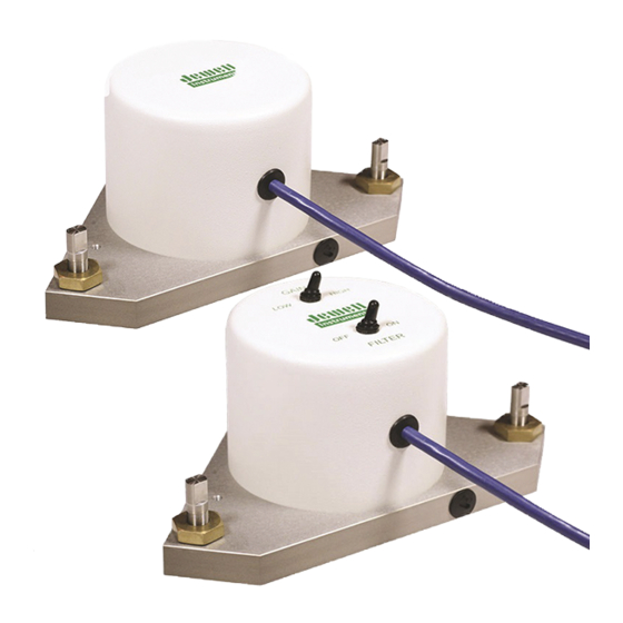
Page 5: Figure 2: Floor Mount Tiltmeter, Model 711-2
Figure 2: Floor Mount Tiltmeter, Model 711-2. Model 700 Series User's Manual B-88-1016, Rev. G... -
Page 6: Figure 3: Platform Tiltmeter, Model 702
Figure 3: Platform Tiltmeter, Model 702. Model 700 Series User's Manual B-88-1016, Rev. G... -
Page 7: Figure 4: Floor Mount Tiltmeter, Model 712
Figure 4: Floor Mount Tiltmeter, Model 712. Model 700 Series User's Manual B-88-1016, Rev. G... -
Page 8: Technical Features
• All tiltmeters are hand-assembled, calibrated, and tested at our plant under stringent quality control standards. • JEWELL maintains complete specifications and test records of every tiltmeter built. Both platform and surface mount tiltmeters function the same: they contain one or two electrolytic level sensors (one for each tilt axis) that produce changes in resistance in response to a rotation of the sensor. -
Page 9: Installation
Before installing any of the tiltmeters, verify that the tiltmeters are functioning properly by following the steps below. The steps are listed using a Jewell Instruments Model 771 Digital Readout Unit (DRU). You may also elect to use a Model 772 Power Supply/Readout/Interface (PSRI) unit, oscilloscope, or batteries and voltmeters. - Page 10 LOW. The outputs of both channels should drop approximately by the ratio between your high- and low-gain scale factors, given in Appendix B. This behavior verifies that the gain switch is working properly. Model 700 Series User's Manual B-88-1016, Rev. G...
-
Page 11: Figure 5A: Platform And Floor Mount Tiltmeter Sign Convention
Figure 5a: Platform and Floor Mount Tiltmeter Sign Convention. Model 700 Series User's Manual B-88-1016, Rev. G... -
Page 12: Figure 5B: Wall Mount Tiltmeter In Installed Position
Figure 5b: Wall Mount Tiltmeter in Installed Position. Model 700 Series User's Manual B-88-1016, Rev. G... -
Page 13: Installing Platform Tiltmeters
A small bulls-eye or carpenter’s level can be used to perform a rough initial leveling of the tiltmeter. The final leveling should be performed by connecting the tiltmeter to a JEWELL Model 771 Digital Readout Unit or batteries and two digital voltmeters. To perform the final leveling, turn the FILTER switch to OFF and the GAIN switch to LOW. -
Page 14: Recording Tiltmeter Data With External Recorders
For example, if the scale factor is 10 mV/arc second and the voltage reading is +2077 mV (+2.077 volts), then the tilt angle is +207.7 arc seconds from sensor null. radian = microradian; 1 mV = 1 millivolt = 0.001 volt Model 700 Series User's Manual B-88-1016, Rev. G... -
Page 15: Maintenance And Troubleshooting
Apart from the procedures described below, the tiltmeters are not field-serviceable. If you encounter problems not described here, please contact Jewell Instruments LLC at (603) 669-6400. A sales representative will assist you in determining the cause of any problem. -
Page 16: Routine Maintenance
JEWELL for repair. Internal connections in stainless steel tiltmeters (Models 702, 712, 715 and 717) can be checked by removing the screws that hold down the tiltmeter dome, removing the dome and exposing the internal electronics. - Page 17 COVERED BY THE WARRANTY. If an inspection of the connections to the printed circuit board does not correct the problem, please call a Jewell Instruments sales representative at (603) 669-6400 for assistance. CAUTION NEVER USE AN OHMMETER TO MEASURE THE TILT SENSORS INSIDE THE TILTMETER.
-
Page 18: Figure 7: Model 83162 Dual-Channel Signal Conditioning Card
Figure 7: Model 83162 Dual-Channel Signal Conditioning Card. Model 700 Series User's Manual B-88-1016, Rev. G... -
Page 19: Appendix A: Warranty And Assistance
After expiration of the warranty, JEWELL will repair the equipment at its factory for parts and labor charges. Products returned after warranty expiration should be accompanied by a purchase order to cover repair costs. -
Page 20: Appendix B: Custom Specifications For Your 700-Series Tiltmeter
Your tiltmeter has two single-pole RC low-pass filters (integrators) selected by the FILTER switch on top of the tiltmeter dome or inside the dome (Model 712). Models 701-2(4X) and 711-2(4X) do not have a filter switch, and therefore have only one filter time constant. Model 700 Series User's Manual B-88-1016, Rev. G... - Page 21 values for filter settings: ON: _____________ seconds OFF: ______________ seconds Output Connector on Tiltmeter Cable Bendix PT06A-12-10P (JEWELL P/N 62302) male plug* Tinned Wires (no connector) Table B2. Connector Pin Assignments and Cable Color Coding Bendix Pin #...
-
Page 22: Appendix C: Guidelines For Installing Surface Mount Tiltmeters
APPENDIX C: Guidelines for Installing Surface Mount Tiltmeters These guidelines will help you achieve stable and reliable tiltmeter readings. Jewell Instruments supplies all of the installation accessories you need for an effective monitoring program. • Surface mount tiltmeters are typically attached to the measurement surface by mounting studs (threaded rods) fastened or anchored into the surface. -
Page 23: Appendix D: Angle Conversion Chart
3600 17453 17.453 0.2094 arc minute= 0.016667 290.89 0.29089 3.4907E arc second= 2.7778E 0.016667 4.8481 4.8481E 5.8178E µradian = 5.7297E 3.4377E 0.20626 0.001 1.200E mm/meter= 0.057297 3.4377 206.26 1000 0.01200 Model 700 Series User's Manual B-88-1016, Rev. G... -
Page 24: Appendix E: Revision Record
APPENDIX E: Revision Record PAGE REV. ECN NO. DESCRIPTION OF CHANGE DATE NOS. "Jewell" was "Applied Geomechanics" 25191 3/19/13 Added Appendix E for revision record Model 700 Series User's Manual B-88-1016, Rev. G...