Table of Contents
Pool, Spa & Pond
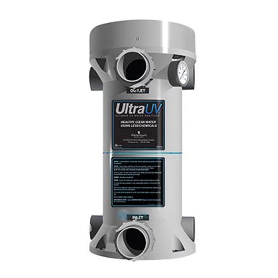
Water Sanitizer 4BJ1
1555 Detrick Avenue. Deland Florida. 32724-2014
Toll Free: 1-866-649-5551 Phone: 407-600-5751
[email protected] www.ultravioletpools.come
004-422-0003-00 REV 031714
IMPORTANT SAFETY INSTRUCTIONS:
READ COMPLETELY BEFORE PROCEEDINg.
When using this electrical equipment, basic safety precautions should
always be followed, including the following:
WARNINg:
• Follow all applicable electrical codes.
• Turn off power at main source before making any electrical connections
or servicing the unit.
• To reduce the risk of electric shock, injury or death disconnect unit from
power supply
• Follow the instructions or risk of serious injury or death could occur!
UV ExPOSURE & PROTECTION:
UV-A and UV-B radiation can have adverse short and long term effects on
the eyes and skin. Never look directly at a UV lamp that is connected to a
power source. Avoid UV skin exposure at all times.
EPA Registered
#084221-AZ-001
INSTALLATION &
OPERATIONS MANUAL
Table of Contents

Related Manuals for Paramount Fitness Ultra UV 004-422-2025-00


Summary of Contents for Paramount Fitness Ultra UV 004-422-2025-00
- Page 1 INSTALLATION & OPERATIONS MANUAL IMPORTANT SAFETY INSTRUCTIONS: READ COMPLETELY BEFORE PROCEEDINg. When using this electrical equipment, basic safety precautions should always be followed, including the following: WARNINg: • Follow all applicable electrical codes. • Turn off power at main source before making any electrical connections or servicing the unit.
-
Page 2: Table Of Contents
Table of Contents Welcome ........................3 General Product Information ..................3 ULTRA UV System Sizing ..................3 Pond Sizing Considerations ..................3 Pond Sizing Chart ......................4 Pool, Spa, Fountain, Water Feature, Water Fall Sizing Chart ......5 First Step In Starting Your Installation ..............6 Locating The Ultra UV Unit .................. -
Page 3: Welcome
WELCOME The ULTRA UV Unit is designed for use in swimming pools, spas, fountains, water features, waterfalls, fish ponds and the like. It is not designed for use in potable (drinking) water installations. Use of this product in applications other than those indicated above will void your warranty and could be harmful to your health or the health of others. -
Page 4: Pond Sizing Chart
POND SIzINg CHART See Chart Below. Maximum Maximum Pond Pond Pond Pond Flow Flow Volume Volume Volume Volume ULTRA UV Part Number Rate Rate 2 Hr. 2 Hr. 3 Hr. 3 Hr. (GPM) (m3/hr) Turnover Turnover Turnover Turnover (GPM) (m3) (GPM) (m3) 004-422-2025-00 230V w/ 1 UV-C Lamp... -
Page 5: Pool, Spa, Fountain, Water Feature, Water Fall Sizing Chart
POOL, SPA, FOUNTAIN, WATER FEATURE, WATER FALL SIzINg CHART Swimming pools and similar water vessels are simple to calculate. See chart below. Maximum Maximum Pool Pool Pool Pool Flow Flow Volume Volume Volume Volume ULTRA UV Part Number Rate Rate 12 Hr. -
Page 6: First Step In Starting Your Installation
FIRST STEP IN STARTINg YOUR INSTALLATION Inspect the ULTRA UV unit for damage, paying close attention to the quartz tube. LOCATINg THE ULTRA UV UNIT Your unit can be installed indoors or outdoors. When considering the location for your ULTRA UV unit, Power keep it close to your power source. -
Page 7: Plumbing The Ultra Uv Unit
PLUMBINg THE ULTRA UV UNIT All plumbing methods are illustrated with and without the bypass option. Your ULTRA UV unit will need to be plumbed into the circulation system. The ULTRA UV unit is plumbed to the discharge side of the filter before the heater. Fig. -
Page 8: Gluing Piping To The Uv Unit
gLUINg PIPINg TO THE UV UNIT Two Inlet/Outlet unions are supplied. Your PVC supply piping should be glued into the union tail pieces using an appropriate primer and ABS to PVC cement. Inlet piping should be supported and should not rest solely upon the unions, to avoid stressing or breaking the unions. -
Page 9: Electrical Bonding (Grounding)
ELECTRICAL BONDINg (gROUNDINg) Locate the grounding lug next to the power cable (Fig. 4). To reduce the risk of electric shock, this terminal must grounding Lug be connected to the grounding means provided in the electrical supply service panel with a continuous copper wire equivalent in size to the circuit conductors supplying this equipment. -
Page 10: Connecting Pressure Switch
CONNECTINg PRESSURE SWITCH Disconnect the power to the ULTRA UV unit. Remove the cover and locate the pressure switch (Fig. 5). Locate the lead with the female spade connector that comes up through a rubber grommet in the Pressure Switch black metal plate (Fig. -
Page 11: Quartz Tube Maintenance
CONSUMER OPERATINg INSTRUCTIONS QUARTz TUBE MAINTENANCE Cleaning quartz tube. The quartz tube requires cleaning every 6 months to ensure optimum performance. 1. Turn off all power to the ULTRA UV unit and all other pool equipment. Unplug the unit from its power receptacle or turn OFF the circuit breaker that is the ULTRA UV’s power source. - Page 12 YOU MUST WEAR PROTECTIVE RUBBER gLOVES. DO NOT HANDLE A HOT LAMP OR SERIOUS BURNS WILL OCCUR. DO NOT TOUCH THE gLASS PART OF THE LAMP AS BODY OILS WILL CREATE HOT SPOTS & gREATLY SHORTEN LAMP LIFE. (Fig. 11) 4.
- Page 13 or needs cleaning use the same cleaning method. The inside of the quartz tube must be completely dried before reassembly. DO NOT USE ABRASIVE CLEANERS OR PADS. 9. Inspect the quartz tube carefully for any cracks or chips and replace the quartz tube if any are found.
- Page 14 12. Then place the aluminum compression washer on the quartz tube. Press down on the aluminum compression washer with an even steady pressure (Fig. 20). This will roll the O-ring into the area between the inside of the black threaded sleeve and the quartz tube.
-
Page 15: Scheduled Uv Lamp(S) Replacement
Fig. 23 SCHEDULED UV LAMP(S) REPLACEMENT The UV lamps have a useful life of approximately 13,000 hours and should be replaced at that time. Fig. 24 Even though the lamp(s) may be glowing after 13,000 hours of operation they have reached the end of their useful life. -
Page 16: Winterization Of Your Ultra Uv Unit
WINTERIzATION OF YOUR ULTRA UV UNIT If you are in a climate where you run your pool, spa, water feature, pond year round, be sure that the flow to the unit continues during any periods of below freezing temperatures. Failure to do so will cause damage to the unit. Option #1 - Removing the unit for the winter. -
Page 17: Faqs
FAQs IS THE ULTRA UV UV UNIT DESIgNED FOR USE IN SALT WATER APPLICATIONS? Yes. Paramount’s ULTRA UV units without the optional stainless steel reactor reflectors are fully compatible with all salt water environments. The quartz tube could require more frequent cleaning in a salt water environment. -
Page 18: Troubleshooting
TROUBLESHOOTINg IDENTIFYINg AND CORRECTINg SYSTEM PROBLEMS The list below will help guide you through any problems you may have at time of initial installation or in the future. For additional assistance, contact your supplier or Paramount Pool & Spa Systems, 295 East Corporate Place, Chandler AZ 85225. - Page 19 d. Verify that the GFCI has not tripped. To verify the operating state of the GFCI, trip the GFCI manually and reset it manually. The GFCI should reset. If it does not, it indicates a fault to ground in the electrical circuit or the ULTRA UV unit itself.
- Page 20 b. If the ULTRA UV unit is located above the water level of the pool or pond and the lamp(s) stay(s) lit when the pump is OFF, replace the pressure switch. THE WATER IS gREEN Green water is an indication that the UV rays generated by the ULTRA UV unit are not effective or are not being generated by the UV lamp(s).
- Page 21 b. If water is present inside the electrical enclosure cover, it will trip the GFCI. Following instructions given previously to remove the quartz tube(s), inspect for quartz tube cracks or breakage or for a bad quartz tube seal. Replace the quartz tube if it is cracked or broken. If not reseal it.
- Page 22 Lamp Unit Configurations • 1 Lamp unit requires 1 single lamp ballast 2" Union Kits 63mm Union Kits • 2 Lamp unit requires 1 dual lamp ballast • 3 Lamp unit requires 1 single lamp ballast Optional 1 dual lamp ballast Flow Switch •...
-
Page 23: Ultra Uv Replacement Parts
ULTRA UV REPLACEMENT PARTS Paramount Part# Description 005-422-2009-11 Cover 005-422-5104-00 UV Lamp Centering Disk Aluminum Sealing Nut Compression Washer Compression Washer O-Ring 005-422-5103-00 Quartz Tube Seal O-Ring 005-422-2009-00 Advance Intellivolt Ballast, 1 Lamp 005-422-2009-01 Advance Intellivolt Ballast, 2 Lamp 005-422-2009-10 Pressure Switch 005-422-9010-00 Ballast Mounting Bracket...