Table of Contents
Quick Links
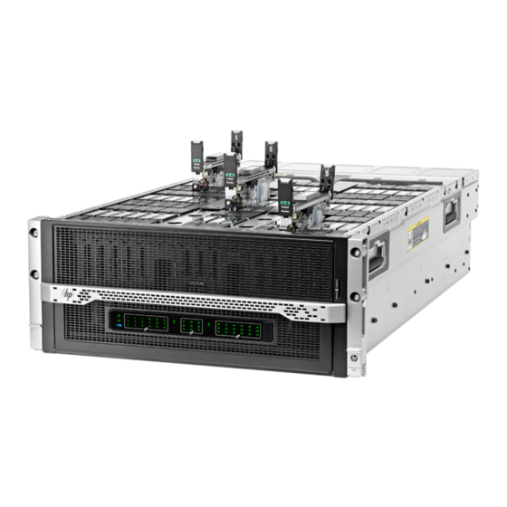
HP Moonshot 1500 Chassis
Setup and Installation Guide
Abstract
This document contains setup, installation, and configuration information for the HP Moonshot System. This document is for the person who installs,
administers, and troubleshoots the HP Moonshot System. HP assumes you are qualified in the servicing of computer equipment and trained in
recognizing hazards in products with hazardous energy levels.
Part Number: 711993-004
June 2014
Edition: 4
Table of Contents

Related Manuals for HP Moonshot 1500


Summary of Contents for HP Moonshot 1500
- Page 1 Abstract This document contains setup, installation, and configuration information for the HP Moonshot System. This document is for the person who installs, administers, and troubleshoots the HP Moonshot System. HP assumes you are qualified in the servicing of computer equipment and trained in recognizing hazards in products with hazardous energy levels.
- Page 2 © Copyright 2013, 2014 Hewlett-Packard Development Company, L.P. The information contained herein is subject to change without notice. The only warranties for HP products and services are set forth in the express warranty statements accompanying such products and services. Nothing herein should be construed as constituting an additional warranty. HP shall not be liable for technical or editorial errors or omissions contained herein.
-
Page 3: Table Of Contents
Moonshot-4QSFP+ Uplink Module LEDs and buttons ................15 HP Moonshot 1500 Chassis Management module components............. 16 HP Moonshot 1500 Chassis Management module LEDs and buttons ............. 17 Chassis internal components........................17 Cartridge slot and switch module bay identification ................18 Cartridge LEDs and buttons ....................... - Page 4 Installing network components ......................29 Cabling the HP Moonshot System ....................36 Cabling overview ............................36 Connecting the Moonshot System to a network ....................36 Data center management network ...................... 36 Data center production network ......................37 Connecting power cables and applying power to the chassis ................. 38 Power-on events ..........................
-
Page 5: Planning The Installation
Moonshot System. Users deploy the firmware updates contained in the Moonshot Component Pack from a command line by using the iLO Chassis Manager CLI or HP Moonshot-45G/180G Switch Module CLI, or by using the included HP Smart Update Manager. Download the latest pack from the HP website (http://www.hp.com/go/moonshot/download). -
Page 6: Hp Advanced Power Manager
HP Advanced Power Manager HP APM is a point of contact for system administration. To install, configure, and access HP APM, see the HP ProLiant SL Advanced Power Manager User Guide in the HP Moonshot Information Library (http://www.hp.com/go/moonshot/docs). Hot-plug power supply calculations For hot-plug power supply specifications and calculators to determine electrical and heat loading for the HP Moonshot System, see the HP Power Advisor on the HP website (http://www.hp.com/go/hppoweradvisor). -
Page 7: Space And Airflow Requirements
WARNING: To reduce the risk of personal injury or damage to the equipment, be sure that: • The rack is bolted to the floor using the concrete anchor kit. The leveling feet extend to the floor. • The full weight of the rack rests on the leveling feet. •... -
Page 8: Temperature Requirements
HP rack products draw cool air in through the front and expel warm air through the rear of the enclosure. Therefore, the front of the rack enclosure must be adequately ventilated to enable ambient room air to enter the enclosure, and the rear of the enclosure must be adequately ventilated to enable the warm air to escape from the enclosure. -
Page 9: Identifying Components And Leds
Identifying components and LEDs HP Moonshot System components Item Description HP Moonshot 1500 Chassis Cartridges* Cartridge blank* Access panel Switch module* Fans (5) Uplink module* Moonshot 1500 CM module Power supplies* * The quantity depends on the configuration ordered. The following documents also ship with the Moonshot System: •... -
Page 10: Chassis Front Panel Components
Chassis front panel components Item Description Bezel ear Backplane assembly release lever Serial label pull tab Bezel ear Chassis front panel LEDs and buttons Item Description LED Status Chassis power LED Flashing Green = The chassis is waiting to power on. Green = Normal operation Amber = Standby operation Off = No power... -
Page 11: Chassis Rear Panel Components
Green = Normal operation Amber = Standby mode Flashing Amber = Degraded condition Flashing Amber (All) = Moonshot 1500 CM module is not installed. Flashing Red = Critical condition Off = Cartridge is not installed or no power exists. Switch module A health... -
Page 12: Fan Bay Numbering
Fan bay numbering Fan LED Status Description The fan is working or the power is off. The fan has failed. Solid amber Power supply bay numbering Identifying components and LEDs 12... -
Page 13: Power Supply Led
Power supply LED Status Description • No AC power to power supply units. Check the AC power cord. • AC is present. Standby output is on; output is disabled. • Power supply failure (includes overvoltage and overtemperature) AC is present and main 12 V output is enabled. Green Uplink module bay identification Moonshot-6SFP Uplink Module components... -
Page 14: Moonshot-6Sfp Uplink Module Leds And Buttons
• HP 10GBASE-DAC SFP+ Any available port can be used to connect to the data center. Ensure the port is populated with supported HP transceiver modules that are compatible with the data center port type. Moonshot-6SFP Uplink Module LEDs and buttons... -
Page 15: Moonshot-4Qsfp+ Uplink Module Components
• HP 40GBASE QSFP+ to 4x10G SFP+ Any available port can be used to connect to the data center. Ensure the port is populated with supported HP transceiver modules that are compatible with the data center port type. Moonshot-4QSFP+ Uplink Module LEDs and buttons... -
Page 16: Hp Moonshot 1500 Chassis Management Module Components
Uplink module Flashing green = Activity activity LED Off = No activity Reset button Resets the switch module HP Moonshot 1500 Chassis Management module components Item Description Label iLO CM management port iLO/MGMT iLO CM link port (disabled by default) -
Page 17: Hp Moonshot 1500 Chassis Management Module Leds And Buttons
LINK Moonshot 1500 CM module UID LED/button — Moonshot 1500 CM module health LED — Chassis internal components Up to 45 cartridges and two switch modules can be installed in the HP Moonshot 1500 Chassis. Identifying components and LEDs 17... -
Page 18: Cartridge Slot And Switch Module Bay Identification
Cartridge slot and switch module bay identification The chassis provides 45 cartridge slots (1-45) and two switch module bays (A-B). Identifying components and LEDs 18... -
Page 19: Cartridge Leds And Buttons
Cartridge LEDs and buttons Item Description Status Cartridge power Green = Normal operation LED/button Amber = Standby operation Off = No power Cartridge health LED Green = Normal operation Flashing amber = Degraded condition Flashing red = Critical condition Off = No power Drive LED* Green = Activity Off = No activity... -
Page 20: Switch Module Button, Sensor, And Leds
Switch module button, sensor, and LEDs Item Description Status Switch module power Green = Normal operation Amber = Standby operation Off = No power Switch module health Green = Normal operation Flashing amber = Degraded condition Flashing red = Critical condition Off = No power Switch module uplink Green = Link... -
Page 21: Installing The Chassis
Due to the height of the Moonshot 1500 Chassis, chassis installation requires either the use of a rack rail adapter kit or a blanking panel. If you ordered a rack rail adapter kit to be installed at the factory, then the blanking panel is not required. - Page 22 HP has not tested or validated the HP Moonshot 1500 Chassis with any third-party racks. Before installing the HP Moonshot 1500 Chassis in a third-party rack, be sure to properly scope the limitations of the rack. Before proceeding with the installation, consider the following: •...
- Page 23 Observe local occupational health and safety requirements and guidelines for manual • material handling. HP recommends removing all installed components from the chassis before installing or • moving the chassis. CAUTION: Be sure to keep the product parallel to the floor when installing the chassis.
- Page 24 Install the chassis into the J-slot on the rails, and then pull it forward. Push in the release lever, and then install the chassis into the rack. CAUTION: Press and hold the "Push" tab on each rail until the chassis begins to slide into the rack.
-
Page 25: Installing The Blanking Panel
Installing the blanking panel If the rack rail adapter kit is not installed on the rack, always install the blanking panel to ensure proper airflow. The blanking panel is not needed when the rack rail adapter kit is installed. To install the component: For round-hole racks, remove the guide pins and replace them with the guide pins included for round-hole racks. -
Page 26: Installing Hp Moonshot System Components
If you perform any of the procedures in this section after powering on the chassis, ensure proper airflow by ensuring that each bay inside the chassis and at the rear of the chassis is populated with either a component or a blank. For component-specific replacement information, see the HP Moonshot 1500 Chassis Installing the chassis 26... -
Page 27: Installing The Moonshot 1500 Cm Module
Maintenance and Service Guide or cartridge-specific user and maintenance guides in the HP Moonshot Information Library (http://www.hp.com/go/moonshot/docs). Installing the Moonshot 1500 CM module Install the component as indicated. Installing a power supply WARNING: To reduce the risk of electric shock or damage to the equipment: Do not disable the power cord grounding plug. -
Page 28: Installing The Fans
To install the component: Install the power supply into the device bay, and then press firmly until the power supply is seated. Installing the fans Install the component as indicated. Installing the chassis 28... -
Page 29: Installing The Cartridge
Installing the cartridge To install the component: Prepare the cartridge. Align and install the cartridge into the chassis. Installing network components • Switch information and guidelines (on page 29) • Removing the uplink module blank (on page 32) • Installing the uplink module (on page 32) •... - Page 30 • Removing any component from bay A or bay B does not disrupt traffic for the other switch assembly. • For the most current product information, see the release notes in the HP Moonshot Information Library (http://www.hp.com/go/moonshot/docs). • Always use the HP recommended firmware version.
- Page 31 Production network mapping The first network interface discovered by the operating system routes traffic through switch A. The second network interface discovered by the operating system routes traffic through switch B. Installing the chassis 31...
- Page 32 Management network mapping All traffic from the service port management interface is routed through the iLO CM management port. Removing the uplink module blank Remove the component as indicated. Installing the uplink module CAUTION: To avoid connectivity loss, do not remove switches already in operation. Installing the chassis 32...
- Page 33 If the switch module is not installed, install the switch module before verifying LEDs. For more information, see "Switch information and guidelines (on page 29)." After both components have been installed, verify the switch firmware is at the HP recommended firmware version. For more information, see the HP Moonshot Component Pack download website (http://www.hp.com/go/moonshot/download).
- Page 34 To install the component: Locate the switch module slot, and then remove the blank. Prepare the switch module for installation. Installing the chassis 34...
- Page 35 Install the access panel, and then return the chassis to the rack. After both components have been installed, verify the switch firmware is at the HP recommended firmware version. For more information, see the HP Moonshot Component Pack download website (http://www.hp.com/go/moonshot/download).
-
Page 36: Cabling The Hp Moonshot System
Data center production network (on page 37) Data center management network To connect the chassis to a management network, connect an Ethernet cable from the Moonshot 1500 CM module to the management network. Always connect to the iLO CM management port first. Do not connect both the iLO CM management port and the iLO CM link port to the same network switch. -
Page 37: Data Center Production Network
Moonshot iLO CM firmware SSH sessions and switch SSH sessions share connectivity through the iLO CM management port. The iLO CM management port is located on the Moonshot 1500 CM module on the rear of the chassis. Data center production network To connect the chassis to a production network, connect to any available SFP+ or QSFP+ port. -
Page 38: Connecting Power Cables And Applying Power To The Chassis
Route all rear panel cables through the cable management arm. For more information about the cable management arm, see the Quick Deploy Rail System Installation Instructions that ship with the Quick Deploy Rail System kit or in the HP Moonshot Information Library (http://www.hp.com/go/moonshot/docs). -
Page 39: Configuring The Hp Moonshot System
Use a serial cable to connect a PC or terminal to the iLO CM management serial port on the Moonshot 1500 CM module. To locate the iLO CM management serial port, see "HP Moonshot 1500 Chassis Management module components (on page 16)."... - Page 40 Obtain the management IP address To determine the management IP address for the Moonshot 1500 CM module, log in to the iLO CM firmware while connected to the iLO CM management serial port. At the prompt, enter the following command:...
-
Page 41: Configure The Switch
[C ] All cartridges update firmware all For more information on updating the firmware, see the HP Moonshot iLO Chassis Management CLI User Guide in the HP Moonshot Information Library (http://www.hp.com/go/moonshot/docs). Configure the switch To configure the Moonshot switch, complete the following steps: Access the CLI locally (on page 42). - Page 42 For detailed configuration information, see the Switch Administrator's Guide and Switch CLI Guide in the HP Moonshot Information Library (http://www.hp.com/go/moonshot/docs). Access the CLI locally To access the CLI interface locally: Use a console cable to connect a PC or terminal to the serial console port on the uplink module.
- Page 43 This step overwrites the previous firmware version. Before committing, be sure no plans exist to downgrade switch firmware. For more information on updating switch firmware, see the Switch Module Administrator's Guide and the Switch Module CLI Command Reference in the HP Moonshot Information Library (http://www.hp.com/go/moonshot/docs). Configuring the HP Moonshot System 43...
-
Page 44: Power Capping
The HP Moonshot System provides a power capping feature that operates at the chassis level. The capping feature can be activated using the iLO CM firmware that runs on each HP Moonshot 1500 chassis. After a power cap is set for the chassis, all the resident cartridges in the chassis will have the same uniform power cap applied to them until the cap is either modified or canceled. - Page 45 Powercap Mode: Max Performance with Redundancy Enter the following command to set the power capacity mode for the chassis: set chassis powercap mode {0|1|2} Example: hpiLO-> set chassis powercap mode 2 Set powercap mode to Full AC/DC Redundancy Mode Configuring the HP Moonshot System 45...
-
Page 46: Troubleshooting
The HP Moonshot System Troubleshooting Guide provides procedures for resolving common problems and comprehensive courses of action for fault isolation and identification, issue resolution, and software maintenance on the HP Moonshot System. The document is available in the HP Moonshot Information Library (http://www.hp.com/go/moonshot/docs). -
Page 47: Regulatory Information
Hewlett-Packard Company, Address: 3000 Hanover Street, Palo Alto, California 94304, U.S. Local representative information (Russian) • HP Russia • HP Belarus • HP Kazakhstan Local representative information (Kazakh) Manufacturing date The manufacturing date is defined by the serial number (HP serial number format for this product): CCSYWWZZZZ Regulatory information 47... -
Page 48: Turkey Rohs Material Content Declaration
These requirements provide reasonable protection against interference with radio and television communications. Installing and using the system in strict accordance with HP instructions minimizes the chances that the system might cause radio or television interference. However, HP does not guarantee that the system does not interfere with radio and television reception. -
Page 49: Electrostatic Discharge
Electrostatic discharge Preventing electrostatic discharge To prevent damaging the system, be aware of the precautions you need to follow when setting up the system or handling parts. A discharge of static electricity from a finger or other conductor may damage system boards or other static-sensitive devices. -
Page 50: Specifications
Specifications Chassis environmental specifications Specification Value — Temperature range* 10°C to 35°C (50°F to 95°F) Operating -30°C to 60°C (-22°F to Non-operating 140°F) — Maximum Wet bulb temperature 28ºC (82.4ºF) Operating 38.7ºC (101.7ºF) Non-operating Relative humidity (non-condensing)** — 10% to 90% Operating 5% to 95% Non-operating... -
Page 51: Support And Other Resources
If during the diagnosis period HP (or HP service providers or service partners) identifies that the repair can be accomplished by the use of a CSR part, HP will ship that part directly to you for replacement. There are two categories of CSR parts: •... - Page 52 HP specifies in the materials shipped with a replacement CSR part whether a defective part must be returned to HP. In cases where it is required to return the defective part to HP, you must ship the defective part back to HP within a defined period of time, normally five (5) business days. The defective part must be returned with the associated documentation in the provided shipping material.
- Page 53 HP sono realizzati con numerosi componenti che possono essere riparati direttamente dal cliente (CSR, Customer Self Repair). Se in fase di diagnostica HP (o un centro di servizi o di assistenza HP) identifica il guasto come riparabile mediante un ricambio CSR, HP lo spedirà direttamente al cliente per la sostituzione.
- Page 54 HP podrá cobrarle por el de sustitución. En el caso de todas sustituciones que lleve a cabo el cliente, HP se hará cargo de todos los gastos de envío y devolución de componentes y escogerá la empresa de transporte que se utilice para dicho servicio.
- Page 55 HP. Informatie over Service Partners vindt u op de HP website (http://www.hp.com/go/selfrepair). Reparo feito pelo cliente Os produtos da HP são projetados com muitas peças para reparo feito pelo cliente (CSR) de modo a minimizar o tempo de reparo e permitir maior flexibilidade na substituição de peças com defeito. Se, durante o período de diagnóstico, a HP (ou fornecedores/parceiros de serviço da HP) concluir que o reparo...
- Page 56 Opcional – Peças cujo reparo feito pelo cliente é opcional. Essas peças também são projetadas para o reparo feito pelo cliente. No entanto, se desejar que a HP as substitua, pode haver ou não a cobrança de taxa adicional, dependendo do tipo de serviço de garantia destinado ao produto.
- Page 57 Support and other resources 57...
- Page 58 Support and other resources 58...
-
Page 59: Acronyms And Abbreviations
Acronyms and abbreviations chassis management CPLD complex programmable logic device DHCP Dynamic Host Configuration Protocol HP APM HP Advanced Power Manager Integrated Lights-Out power distribution unit QSFP+ enhanced quad small form-factor pluggable Secure Copy Protocol small form-factor pluggable SFP+ enhanced small form-factor pluggable... - Page 60 TFTP Trivial File Transfer Protocol uninterruptible power system Acronyms and abbreviations 60...
-
Page 61: Documentation Feedback
Documentation feedback HP is committed to providing documentation that meets your needs. To help us improve the documentation, send any errors, suggestions, or comments to Documentation Feedback (mailto:[email protected]). Include the document title and part number, version number, or the URL when submitting your feedback. -
Page 62: Index
12 contacting HP 51 bay numbering, uplink module 13 cooling power, configuring 5 before you contact HP 51 CSR (customer self repair) 51 Belarus Kazakhstan Russia marking 47 customer self repair (CSR) 51 bezel ear 10... - Page 63 CM link port activity LED 17 Moonshot 1500 CM module health LED 17 iLO CM link port link LED 17 Moonshot 1500 CM module LEDs and buttons 17 iLO CM management port 16 Moonshot 1500 CM module MicroSD slot 16...
- Page 64 USB connector 16 regulatory compliance notices 5, 47 remote management 42 required information 51 warranty information 48 requirements, power 5, 6 website, HP 51 requirements, site 5 resources 46, 51 RoHS 48 safety considerations 5, 49 safety information 5 serial label pull tab 10...