Table of Contents
Quick Links
Table of Contents

Related Manuals for Panasonic FP Series


Summary of Contents for Panasonic FP Series
- Page 1 Telecontrol FP Modem–EU Technical Manual...
- Page 2 This manual and everything described in it are copyrighted. You may not copy this manual, in whole or part, without written consent of Panasonic Electric Works Europe AG (PEWEU). PEWEU pursues a policy of continuous improvement of the design and performance of its products, therefore, we reserve the right to change the manual/product without notice.
- Page 3 Important Symbols One or more of the following symbols may be used in this manual: Warning. The warning triangle indicates especially important safety instructions. If they are not adhered to, the results could be: • fatal or critical injury and/or •...
- Page 4 Summarizes key points in a concise manner. Provides helpful keyboard shortcuts. Provides brief explanation of a function, e.g. why or when you should use it. next page Indicates that the text will be continued on the next page.
-
Page 6: Table Of Contents
Table of Contents FP Modem-EU Technical Manual Table of Contents Overview................. 1 Advantages of the FP Modem-EU ............. 2 Important Functions of the FP Modem-EU ..........3 Product Names and Numbers ..............4 Version-Up History..................5 Compatibility to the FP-Modem 14.4 ............7 Hardware Installation ............ - Page 7 FP Modem-EU Technical Manual Table of Contents Modem Control/Dial-up Connections ........ 31 Modem Control and RS232C Interface ............32 Input of AT Commands ................33 Syntax ......................34 Steps for Establishing and Terminating a Connection ......35 3.4.1 Establishing a Connection................35 3.4.2 Terminating a Connection ................36 User Profiles and Factory Settings............37 Password Protection and Call Back Function ..........39 DTMF Alarm and DTMF Telecontrol ............40...
- Page 8 Table of Contents FP Modem-EU Technical Manual 3.10 Transmission Modes................48 3.11 Terminating the Handshaking Phase............49 3.12 Disconnection with the Break Signal ............50 3.13 Communication Methods and Protocols ..........51 3.14 Error Correction and Data Compression ..........52 3.15 Modem Self-Diagnostic Function.............
- Page 9 FP Modem-EU Technical Manual Table of Contents AT Commands/Registers/Modem Messages ....67 Command Tables ..................68 Register Settings ..................75 Modem Messages ..................78 Remote Networking with Windows........81 Modem Setup for FP Web-Server and Windows ........82 Server’s Side: FP Web-Server and PLC Setup........83 Client’s Side: Windows Dial-up Networking Setup ........85 Client’s Side: Windows Dialing Procedures ..........94 Glossary ................
-
Page 10: Overview
Chapter 1 Overview... -
Page 11: Advantages Of The Fp Modem-Eu
FP Modem-EU Technical Manual Overview 1.1 Advantages of the FP Modem-EU The FP Modem-EU was mainly designed for data exchange between programmable logic controllers (PLCs) in an industrial environment via analog telephone network connections. The following important features distinguish the FP Modem-EU from other standard modems for personal computers: •... -
Page 12: Important Functions Of The Fp Modem-Eu
• PLC <-> PC communication: You can use the modem for remote programming and monitoring (dial-up and leased line mode ) with Panasonic PLCs of the FP-Series. • PLC <-> PLC communication: Communication can also be carried out via COM-Port with the help of the FPWIN Pro Library "Modem". -
Page 13: Product Names And Numbers
FP Modem-EU Technical Manual Overview 1.3 Product Names and Numbers Product name Product number FP Modem-EU Unit FPMODEMEU FPWIN Pro Library "Modem" NCL-CMEU-LIB FP Modem-EU RS232C Cable for FP0 COM Port CABMODPLC111 FP Modem-EU RS232C Cable for FP1/FP-M/FP2/FP10SH COM Port CABMODPLC211 FP Modem-EU Technical Manual ACGM0138V13END... -
Page 14: Version-Up History
1.4 Version-Up History FP Modem-EU Technical Manual 1.4 Version-Up History Version 1.21 In April 2005 the FP-Modem-EU Version 1.21 was introduced (see label) with firmware version 1.38 (see ATi3 (see "Command Tables" on page 68)). It includes the following enhancements: •... - Page 15 FP Modem-EU Technical Manual Overview PSTN provider (for both the sender and the receiver). Most European PSTN providers offer the CLIP function: Austria, Belgium, France, Germany, Greece, Italy, Luxembourg, Norway, Poland, Spain, Turkey (Finland and Switzerland will soon follow). The CLIP decoder (see "CLIP Function" on page 46) of the FP-Modem-EU can be enabled with AT%G1 or AT%G3.
-
Page 16: Compatibility To The Fp-Modem 14.4
FP-Modem 14.4. Nevertheless there is a series of changes, both in design and concerning the command set. Some commands were replaced in order to more closely reflect the customary Hayes standard. This does not have any influence on the operation with the Panasonic controllers and the associated user and technology libraries. What has changed? -
Page 18: Hardware Installation
Chapter 2 Hardware Installation... -
Page 19: Fp Modem-Eu Unit Package
FP Modem-EU Technical Manual Hardware Installation 2.1 FP Modem-EU Unit Package The FP Modem-EU unit package contains: • one FP Modem-EU • a 24V DC power cable • a leaflet providing installation instructions • Phoenix 3-pin screw terminal • an RJ12-RJ12 telephone cable... -
Page 20: Part Names, Functions And Dimensions
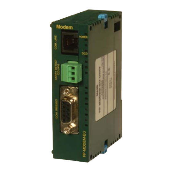
2.2 Part Names, Functions and Dimensions FP Modem-EU Technical Manual 2.2 Part Names, Functions and Dimensions 25.0 60.0 Units: mm 1. Telephone connection jack (RJ12) for dial-up lines, leased line or multipoint lines (middle two wires). An RJ12 to RJ12 cable is supplied with the FP Modem-EU. 2. -
Page 21: Dip Switches
FP Modem-EU Technical Manual Hardware Installation 2.3 DIP Switches Peel the seal off the side of the unit to expose the DIP switches. Seal DIP Switch Function DIP-1 ON = Leased line mode (Leased Line, LL) DIP-2 ON = Multipoint Operation (MP) DIP-3 Leased line: Multipoint:... - Page 22 2.3 DIP Switches FP Modem-EU Technical Manual It is possible that the very first FP Modem-EU's DIP4 function will not work correctly with a completely new modem from stock. If this happens, please use the AT*W command to set up the baud rate.
-
Page 23: Technical Data
FP Modem-EU Technical Manual Hardware Installation 2.4 Technical Data Generalities Dimensions Height 90 mm, Width 25 mm, Depth 64 mm Connection to the telephone RJ12 jack and RJ12-RJ12 cable network (The cable is supplied with the FP Modem-EU.) Carrier detect connection 3-pin Phoenix screw terminal port plug RS232C port 9-pin SUB-D female plug on the front side... - Page 24 2.4 Technical Data FP Modem-EU Technical Manual Modem specifications Operation modes V.32bis 4800 bps, 7200 bps, 9600 bps, 14400 bps full duplex V.32 4800 bps, 7200 bps, 9600 bps full duplex V.22bis 2400 bps full duplex V.22 1200 bps full duplex V.23 1200/75 bps full duplex, 75/1200 full duplex bps 1200/1200 half duplex V.21...
-
Page 25: Important Notes
FP Modem-EU Technical Manual Hardware Installation 2.5 Important Notes Please, read the following notes carefully before installing your FP Modem-EU. ATTENTION! Be sure to install the FP Modem-EU unit in locations designed for electrical equipment, e.g. in a closed metal cabinet such as a switch cabinet. - Page 26 2.5 Important Notes FP Modem-EU Technical Manual • Avoid installing the unit in the following locations: Ambient temperatures outside the range of 0°C to 55°C/32°F to 131°F Ambient humidity outside the range of 30% to 85% RH Sudden temperature changes causing condensation Inflammable or corrosive gases Excessive airborne dust or metal particles Benzine, paint thinner, alcohol or other organic solvents or strong...
- Page 27 FP Modem-EU Technical Manual Hardware Installation • Installation space Leave at least 50mm of space between the wiring ducts of the unit and other devices to allow heat radiation and unit replacement. 50mm or more 50mm or more Maintain a minimum of 100mm between devices to avoid adverse affects from noise and heat when installing a device or panel door to the front of the FP Modem-EU.
-
Page 28: Mechanical Installation
2.6 Mechanical Installation FP Modem-EU Technical Manual 2.6 Mechanical Installation a) Adding to FP0: 1. Raise the expansion hooks on the top and bottom sides of the unit with a screwdriver 2. You can align the pins and holes in the four corners of the control unit and expansion unit, and insert the pins into the holes so that there is no gap between the units However you need not necessarily connect the FP Modem-EU in this way. - Page 29 FP Modem-EU Technical Manual Hardware Installation 3. Press down the expansion hooks raised in step 2 to secure the unit b) Attachment to DIN Rails: • The FP Modem-EU unit enables a one-touch attachment to DIN rails. 1. Fit the upper hook of the FP Modem-EU onto the DIN rail 2.
- Page 30 2.6 Mechanical Installation FP Modem-EU Technical Manual 3. Lift up the FP0 unit and remove it from the rail FP Modem-EU DIN rail DIN rail attachment lever Slotted screwdriver d) Installation Using FP0 Slim Type Mounting Plate • Use M4 size pan-head screws for attachment of FP0 slim type mounting plate (AFP0803) to mounting panel.
- Page 31 FP Modem-EU Technical Manual Hardware Installation Example: Two Expansion Units e) Installation Using FP0 Flat Type Mounting Plate • Use M4 size pan-head screws to attach FP0 flat type mounting plate (AFP0804) and install according to the dimensions shown below. 1.
- Page 32 2.6 Mechanical Installation FP Modem-EU Technical Manual 3. Align the expansion hooks with the plate and press the hooks back down FP0 flat type mounting plate An FP Modem-EU with an attached FP0 flat type mounting plate can also be installed sideways on a DIN rail.
-
Page 33: Wiring
FP Modem-EU Technical Manual Hardware Installation 2.7 Wiring This section provides information on the power supply and the operating voltage, as well as the DCD output and the RS232C cables. The connection to the telephone line will also be explained. 2.7.1 Power Supply and Operating Voltage Connecting the Power Supply The FP Modem-EU will turn on as soon as the power supply has been connected. -
Page 34: Dcd (Data Carrier Detect) Output
2.7 Wiring FP Modem-EU Technical Manual Overvoltage can damage the product! Exceeding the limit of the range of the operating voltage can lead to the destruction of the product and therefore it has to be avoided under all circumstances. 2.7.2 DCD (Data Carrier Detect) Output The DCD output is an ideal method for monitoring the line connect status. -
Page 35: Rs232C Cables
Hardware Installation Wiring Diagram The 24V digital signal is needed because the RS232C interface of the Panasonic PLC does not support handshake or modem control lines. The connect status message NO CARRIER (via RS232C) cannot be reliably detected during a data communication connection. - Page 36 2.7 Wiring FP Modem-EU Technical Manual COM Port: FP0/e COM Port: FP1/M/2/2SH/10SH using cable [CABMODPLC111] SDU FP2/3/C [CABMODPLC211] Wire color Modem 9-pin PLC 9-pin Modem 9-pin D-sub jack (male) D-sub jack (male) D-sub jack (male) 3 TXD 3 TXD green S (SD) 2 RXD 2 RXD...
-
Page 37: Connection To The Telephone Line
FP Modem-EU Technical Manual Hardware Installation 2.7.4 Connection to the Telephone Line A cable with a RJ12 jack at both ends is supplied with the FP Modem-EU. One end connects to the FP Modem-EU the other end to the dial-up, leased line or multipoint network. For connections to European public dial-up networks a special, national RJ12 adapter is needed. -
Page 38: Cable Length/Installation For Leased Line/Multipoint Systems
2.7 Wiring FP Modem-EU Technical Manual 2.7.5 Cable Length/Installation for Leased Line/Multipoint Systems If the FP-Modem-EU is to be connected to private cable installations (leased line or multipoint mode) please consider the following: • Assume that neither the quality of the cable nor the noise on the cable has been defined! •... -
Page 40: Modem Control/Dial-Up Connections
Chapter 3 Modem Control/Dial-up Connections... -
Page 41: Modem Control And Rs232C Interface
FP Modem-EU Technical Manual Modem Control/Dial-up Connections 3.1 Modem Control and RS232C Interface Please make sure for the command and dial-up mode that DIP switches 1 and 2 are both OFF (see "DIP Switches" on page 12). Interfacing with the controller (computer or PLC) often referred to as DTE (Data Terminal Equipment) is done through a serial asynchronous RS232C interface. -
Page 42: Input Of At Commands
3.2 Input of AT Commands FP Modem-EU Technical Manual 3.2 Input of AT Commands The modem is operated from the controller (PLC, computer) by using AT commands according to the Hayes Standard. Therefore the modem is in command mode which is reached after the switching on and the termination of a connection (DIP 1 = OFF, DIP 2 = OFF). -
Page 43: Syntax
FP Modem-EU Technical Manual Modem Control/Dial-up Connections 3.3 Syntax All Hayes commands (see "Command Tables" on page 68) begin with the ASCII character AT (Abbreviation for: Attention). These characters are analyzed by the modem, decoding bit rate, word length and parity of the command string. The modem interprets all successive characters as commands. -
Page 44: Steps For Establishing And Terminating A Connection
3.4 Steps for Establishing and Terminating a Connection FP Modem-EU Technical Manual 3.4 Steps for Establishing and Terminating a Connection If the modem is in data mode, you can get back to the command mode with the Escape command +++ (without AT!). You can switch back to the data mode with ATO. Controller and modem are ready for operation (Power LED is on.) The external telephone cable has been connected to the telephone jack (e.g. -
Page 45: Terminating A Connection
FP Modem-EU Technical Manual Modem Control/Dial-up Connections 3.4.2 Terminating a Connection The data connection is maintained until the modem: • has received the command to hang up (+++ ATH) from the controller and responds with NO CARRIER • cannot detect the carrier anymore (reason: interference too severe, carrier is no longer active) and is responding with NO CARRIER •... -
Page 46: User Profiles And Factory Settings
3.5 User Profiles and Factory Settings FP Modem-EU Technical Manual 3.5 User Profiles and Factory Settings The following commands recall and/or store the user profiles and factory settings of the modem: Command Function AT&V The modem outputs three different configuration profiles: the currently active profile "ACTIVE PROFILE", the stored profile 0 "STORED PROFILE0"... - Page 47 FP Modem-EU Technical Manual Modem Control/Dial-up Connections STORED PROFILE 0: E1 F0 L2 M1 Q0 R0 T V1 W2 X3 Y0 &C1 &D0 &K0 &L0 &M0 &N0 &R0 &S0 &X0 %A000 %B1 %C0 %E1 %F0 %G0 %K1 %P0 %S0 \A3 \C0 \E0 \G0 \J0 \K6 \N3 \T000 S00:001 S07:045 S10:014 S16:2FH S21:20H S22:66H S23:27H S25:005 S26:001 S27:000 S28:000 S29:04H S30:000 S80:000 S91:000 S92:013 S93:020 S94:013 S104:000...
-
Page 48: Password Protection And Call Back Function
3.6 Password Protection and Call Back Function FP Modem-EU Technical Manual 3.6 Password Protection and Call Back Function Password protection for technical facilities (e.g. that are connected to the public telephone network for telemaintenance) should definitely be activated in order to prevent malicious or unintended calls. -
Page 49: Dtmf Alarm And Dtmf Telecontrol
FP Modem-EU Technical Manual Modem Control/Dial-up Connections 3.7 DTMF Alarm and DTMF Telecontrol You can use the FP Modem-EU to send DTMF alarms or decode DTMF tones for telecontrol. 3.7.1 Sending a DTMF Alarm When the FP Modem-EU sends out DTMF tones for alarming: •... -
Page 50: Decoding Dtmf Tones For Remote Control
3.7 DTMF Alarm and DTMF Telecontrol FP Modem-EU Technical Manual 3.7.2 Decoding DTMF Tones for Remote Control When the FP Modem-EU decodes DTMF tones for remote controlling: • The modem dials up a voice telephone (or vice versa). • The human operator uses touch keys to send out DTMF tones. •... -
Page 51: Ascii-Fax Function
FP Modem-EU Technical Manual Modem Control/Dial-up Connections 3.8 ASCII-Fax Function Important Features • Easy generation and delivery of a text based fax page • For example, a PLC can send out an alarm text to a fax machine with up to 8 text lines and up to 80 characters per line •... -
Page 52: Fax Characters (Hex)
3.8 ASCII-Fax Function FP Modem-EU Technical Manual modem starts dialing the stored number. The converting can take some time (about 30 seconds to 1 minute). If the fax has been sent successfully, you receive the hang-up message (class2) and OK or ERROR as a response. -
Page 53: Ascii-Fax Error Messages
FP Modem-EU Technical Manual Modem Control/Dial-up Connections 3.8.2 ASCII-Fax Error Messages Termination Description status codes Start and termination of call Connection terminated normally and correctly Ring detected without successful handshake Call aborted by +FK or AN No loop current 10 - 19 Transmission phase A and various error messages Unspecified error in transmission phase A No response (T.30 T1 Timeout) 20-39... - Page 54 3.8 ASCII-Fax Function FP Modem-EU Technical Manual Termination Description status codes EOL missing after 5 seconds Unused code DCE to DTE buffer overflow Erroneous CRC or data frame (ECM or BFT mode) 100-119 Reception phase D, abort errors Unspecified error in reception phase D RSPREC received invalid response COMREC received invalid response Continuation impossible after PIN or PIP error...
-
Page 55: Clip Function
FP Modem-EU Technical Manual Modem Control/Dial-up Connections 3.9 CLIP Function We have included a CLIP (Calling Line Identification Presentation) decoder in FP Modem-EU V1.2 (see "Version-Up History" on page 5). The CLIP function enables the modem that receives an incoming call to decode the telephone number of the caller. -
Page 56: Example Setups
3.9 CLIP Function FP Modem-EU Technical Manual c.) Selective Call Mode A selective call acceptance can be enabled with AT%G3. However, you must define acceptable calling telephone numbers with AT&Z1= and/or AT&Z2=. With the next ring, the modem analyzes the calling telephone number, and the call is only accepted if the last numbers match the &Z1 or &Z2 settings. -
Page 57: Transmission Modes
FP Modem-EU Technical Manual Modem Control/Dial-up Connections 3.10 Transmission Modes Four different modes can be adjusted for data transmission via the telephone line: • NORMAL mode: automatic adjustment of the line transmission speed, no error correction, no data compression • DIRECT mode: command sets modem to direct data connection, RS232C baud rate = transmission speed (error correction is switched off) Avoid this mode if you have little experience with modems. -
Page 58: Terminating The Handshaking Phase
3.11 Terminating the Handshaking Phase FP Modem-EU Technical Manual 3.11 Terminating the Handshaking Phase At the beginning of each connection procedure, a handshake phase is executed automatically in order to determine the optimum transmission speed. The handshake phase might take a few seconds. -
Page 59: Disconnection With The Break Signal
FP Modem-EU Technical Manual Modem Control/Dial-up Connections 3.12 Disconnection with the Break Signal The \B command sends a signal in order to terminate the connection (break signal) to the remote modem. If you have established a normal (i.e. non-MNP) connection, enter a number after this command. -
Page 60: Communication Methods And Protocols
3.13 Communication Methods and Protocols FP Modem-EU Technical Manual 3.13 Communication Methods and Protocols The data flow processed by the modem is comprised of two different components. In the digital part to the controller (computer, PLC ...), either data or control commands for the modem are being transmitted. -
Page 61: Error Correction And Data Compression
FP Modem-EU Technical Manual Modem Control/Dial-up Connections 3.14 Error Correction and Data Compression During transmission, errors may occur due to noise interference in the telephone line or due to distortion of the signals. To ensure high data safety, the data are incorporated in an error protocol, i.e. -
Page 62: Modem Self-Diagnostic Function
3.15 Modem Self-Diagnostic Function FP Modem-EU Technical Manual 3.15 Modem Self-Diagnostic Function With the AT\M command you can start a self diagnosis of the modem. It contains the following tests: Controller Modem-Chip EPROM NVROM SRAM Afterwards the modem automatically performs a Power-On-Reset, because all parameters in the SRAM are being overwritten due to the self diagnosis. -
Page 63: Plc Remote Programming With Fpwin Pro
FP Modem-EU Technical Manual Modem Control/Dial-up Connections 3.16 PLC Remote Programming with FPWIN Pro The FP Modem-EU can be used for remote programming, monitoring, etc. with FPWIN Pro. If the "M_CMEU_Lib" is not used, the modems should be set up in the following way: FP Modem-EU on the computer: •... -
Page 64: Modem Library For Fpwin Pro
3.17 Modem Library for FPWIN Pro FP Modem-EU Technical Manual 3.17 Modem Library for FPWIN Pro The modem library developed for FPWIN Pro provides you with many convenient function blocks that save you programming time. For example, the library enables a PLC connected to the modem to: •... - Page 65 FP Modem-EU Technical Manual Modem Control/Dial-up Connections FB name Description Picture M_CM_ASCII_Fax Dial out and Send fax M_CM_DTMF_Remote Voice Dial up / Pick up / DTMF Send / Receive M_CM_MEWmaster10 MEWTOCOL Master Communication...
-
Page 66: Cable Networks/Permanent Connections
Chapter 4 Cable Networks/Permanent Connections... -
Page 67: Leased Line Mode
FP Modem-EU Technical Manual Cable Networks/Permanent Connections 4.1 Leased Line Mode The FP Modem-EU can be operated on two-wire private cable or leased lines. 2-wire cable or leased line RS232C RS232C • DIP switch activation and master / slave selection •... -
Page 68: Recommendations For Leased Line Mode
4.1 Leased Line Mode FP Modem-EU Technical Manual Master or Slave DIP-SW4 Remark Fixed baud rate 19200 bps 8o1 (8 data, odd parity, 1 stop bit) Selectable baud rate The last baud rate used in command mode is selected. Selectable baud rate: If you use a baud rate other than 19200 8o1, carry out the following procedure. -
Page 69: Maximum Line Length
FP Modem-EU Technical Manual Cable Networks/Permanent Connections 4.1.4 Maximum Line Length With the following settings, communication was possible over a distance of up to 22 km: • telephone cable (diameter: 0.6 mm), realized with a simulator • no noise, no influence, no disturbances •... -
Page 70: Multipoint Operation
4.2 Multipoint Operation FP Modem-EU Technical Manual 4.2 Multipoint Operation The FP Modem-EU can be operated on a two-wire private cable network. 2-wire cable network RS232C RS232C RS232C FP Modem-EU FP Modem-EU FP Modem-EU • DIP switch activation and selection: PC/RTS Transparent mode •... -
Page 71: Enable Multipoint Mode With Dip Switches
FP Modem-EU Technical Manual Cable Networks/Permanent Connections 4.2.1 Enable Multipoint Mode with DIP Switches Multipoint operation makes it possible to run multiple modems on a two-wire cable network. To activate the multipoint operation mode, set up the FP Modem-EU as follows: DIP1 DIP2 DIP3... -
Page 72: Description Of Multipoint Operation
4.2 Multipoint Operation FP Modem-EU Technical Manual 5. Activate the multipoint mode with DIP switches 1, 2 and 3 as described above, but leave DIP switch 4 OFF If you want to use an FP-Sigma PLC for Multipoint communication via FP Modem-EU, you must use the FP Modem-EU V1.2 or higher because the FP-Sigma does not support a baud rate of 1200 bps. -
Page 73: Error Correction In Multipoint Mode
FP Modem-EU Technical Manual Cable Networks/Permanent Connections 4.2.3 Error Correction in Multipoint Mode Multipoint communication is only possible in V.23 line modulation mode. In multipoint mode no automatic error correction is done (in contrast to dial-up or leased line mode). In multipoint mode the modems do not execute an error handling protocol, i.e. - Page 74 4.2 Multipoint Operation FP Modem-EU Technical Manual The FP Modem-EU (multipoint mode) is equipped with a built-in terminating resistor that can be activated/deactivated by a software command during the setup of the modem. For this purpose, you connect the modem to a computer and use a standard terminal program (for example Hyperterminal) to enter the special modem AT commands for setting up the multipoint parameters.
-
Page 75: Maximum Line Length
FP Modem-EU Technical Manual Cable Networks/Permanent Connections 4.2.5 Maximum Line Length Maximum line length tested by Panasonic: • straight telephone cable (diameter: 0.6 mm), realized with simulator • no noise, no influence, no disturbances • two modems • multipoint PLC mode (default level and delay) •... -
Page 76: At Commands/Registers/Modem Messages
Chapter 5 AT Commands/Registers/Modem Messages... -
Page 77: Command Tables
FP Modem-EU Technical Manual AT Commands/Registers/Modem Messages 5.1 Command Tables List of all available AT commands and their function. The S registers belonging to the commands are also listed (see "Register Settings" on page 75). All commands start with the characters AT, e.g. - Page 78 5.1 Command Tables FP Modem-EU Technical Manual Command Description Hang up ATH or ATH0 and initiate the termination of the connection n=1 If hung up, establish a connection and switch to command mode 0 = Product code 1 = precalculated checksum 2 = memory test, calculates the checksum and compares to stored value, reports OK, if the checksums are equal, otherwise reports ERROR 3 = Report firmware version, model and interface type...
- Page 79 FP Modem-EU Technical Manual AT Commands/Registers/Modem Messages Command Description &Fn n=0 or only AT&F: recall factory setting 0 n=1 recall factory setting 1 &Kn Note: This command replaced AT\Q ! n=0 DTE/DCE flow control switched off n=3 switch on RTS/CTS DTE/DCE flow control n=4 switch on XON/XOFF DTE/DCE flow control n=5 switch on unidirectional XON/XOFF flow control &Nn...
- Page 80 5.1 Command Tables FP Modem-EU Technical Manual Command Description Defines one out of three possibilities to process a break signal, cf. AT\Bn (see "Disconnection with the Break Signal" on page 50). If the modem receives a break signal from the DTE: n=0,2,4 set to operation mode, no break signal is being sent to remote modem n=1 clear buffer and send break signal to remote modem n=3 send break signal to remote modem immediately...
- Page 81 FP Modem-EU Technical Manual AT Commands/Registers/Modem Messages Command Description Output of test signals, e.g. DTMF tones (during online mode) A continuous tone output is generated The modem is ready for more commands/ calls only after sending any character via RS232C to the modem (see "DTMF Alarm and DTMF Telecontrol"...
- Page 82 5.1 Command Tables FP Modem-EU Technical Manual Command Description n=0 NORMAL mode: automatic adjustment of the line transmission speed, no error correction, no data compression n=1 DIRECT mode: command sets modem to direct data connection, RS232C baud rate = line transmission speed (error correction is switched off) Caution! As soon as the connection is established the RS232C baud rate is automatically adjusted...
-
Page 83
FP Modem-EU Technical Manual AT Commands/Registers/Modem Messages Command Description Display password (identical with AT*P?) Entering the password: AT*P=xxxx
You can enter up to 7 characters. These characters may contain letters and numbers and even _-$*+#:;&/\() . Lower case letters are transformed into upper case letters when they are entered! The password you have entered can be displayed with AT*P? or AT*L You can delete the password with AT*P=. -
Page 84: Register Settings
5.2 Register Settings FP Modem-EU Technical Manual 5.2 Register Settings The FP Modem-EU has a number of internal registers at its disposal, i.e. the S registers, through which operation can be controlled. One can distinguish between two types of registers: •... - Page 85 FP Modem-EU Technical Manual AT Commands/Registers/Modem Messages Description Range Factory of values Setting S9 * Period of time (in 1/10 seconds) that a carrier must be present before the 0 - 255 modem establishes the DCD signal. S10 * Period of time (in 1/10 seconds) between the recognition of a lost carrier and 5 - 200 the termination of the connection S11 *...
- Page 86 5.2 Register Settings FP Modem-EU Technical Manual Description Range Factory of values Setting S104* Maximum connection time: Sets the period of time the modem remains online 0-255 before the connection is automatically aborted. Resolution: 1 Minute 0 (zero) for disabling the timer function...
-
Page 87: Modem Messages
FP Modem-EU Technical Manual AT Commands/Registers/Modem Messages 5.3 Modem Messages The modem generates messages as an answer to commands and in case of errors. This enables the control unit to control the execution of the commands and to monitor the operation mode of the modem. - Page 88 5.3 Modem Messages FP Modem-EU Technical Manual Message Meaning long (text) numerical PROTOCOL: ALT Error correction according to MNP PROTOCOL: ALT-CELL Error correction according to MNP10 Modem Messages Controlled by the ATXn Command Modem messages are only output by the modem if the modem was set up with the appropriate ATXn command.
- Page 89 FP Modem-EU Technical Manual AT Commands/Registers/Modem Messages numerical long (text) 0 1 2 3 CONNECT1200 TX/75RX DELAYED BLACKLISTED DATA CARRIER 300 CARRIER 1200/75 CARRIER 75/1200 CARRIER 1200 CARRIER 2400 CARRIER 4800 CARRIER 7200 CARRIER 9600 CARRIER 12000 CARRIER 14400 COMPRESSION: CLASS 5 COMPRESSION: NONE PROTOCOL: NONE PROTOCOL: LAP-M...
-
Page 90: Remote Networking With Windows
Chapter 6 Remote Networking with Windows... -
Page 91: Modem Setup For Fp Web-Server And Windows
FP Modem-EU Technical Manual Remote Networking with Windows 6.1 Modem Setup for FP Web-Server and Windows This chapter informs you on how to set up Windows 95/98 or Windows NT to communicate via FP Modem-EU and dial-up networking with the PPP-Server of the FP Web-Server. PLC/FP Modem-EU setup •... -
Page 92: Server's Side: Fp Web-Server And Plc Setup
6.2 Server’s Side: FP Web-Server and PLC Setup FP Modem-EU Technical Manual 6.2 Server’s Side: FP Web-Server and PLC Setup FP Web-Server Setup Please refer to the Configurator online help for detailed information on the PPP-Server setup and an IP configuration example. 1. - Page 93 FP Modem-EU Technical Manual Remote Networking with Windows 9. Please also remember to enter your user name and password in the Config Wiring of the FP Modem-EU and the FP Web-Server 1. Make sure that all DIP switches of the FP Modem-EU are set to OFF (default setting) 2.
-
Page 94: Client's Side: Windows Dial-Up Networking Setup
There is a Windows driver file that makes it possible to install the FP Modem-EU for Windows. You can find the driver file "MdmFPmodem.inf" on the CD of the Control FP WEB Configurator Tool or you can purchase it from your local Panasonic dealer. - Page 95 FP Modem-EU Technical Manual Remote Networking with Windows 5. In order to add a modem, click on the Add button 6. Check Don’t detect my modem: I will select it from a list 7. Select Next...
- Page 96 6.3 Client’s Side: Windows Dial-up Networking Setup FP Modem-EU Technical Manual 8. Select button Have Disk 9. Enter the path for the driver file "MdmFPmodem.inf" You can use Browse to locate the file in your temporary folder.
- Page 97 FP Modem-EU Technical Manual Remote Networking with Windows 10. Select "FP Modem-EU" 11. Click Next (or OK) 12. Select the COM port of the computer to be used (i.e. COM2) 13. Click Next (or OK)
- Page 98 6.3 Client’s Side: Windows Dial-up Networking Setup FP Modem-EU Technical Manual 14. Click Finish 15. Back in Modems Properties screen, select the new FP Modem-EU 16. Click Properties...
- Page 99 FP Modem-EU Technical Manual Remote Networking with Windows 17. Set the maximum speed to the same value as specified in the FP Web-Server configuration (i.e. 19200 bps) 18. Please make sure Wait for dial tone before dialing is not checked 19.
- Page 100 6.3 Client’s Side: Windows Dial-up Networking Setup FP Modem-EU Technical Manual Configuration of the Dial-up Networking Programs Accessories (Communications ) Dial-up 1. Start Networking 2. Establish a new connection by double-clicking the New button 3. Enter a name for this connection For example enter "FP Web-Server via FP Modem-EU".
- Page 101 FP Modem-EU Technical Manual Remote Networking with Windows 4. Select FP Modem-EU in the Dial using field 5. Click Next (or OK) 6. Enter the number of the distant FP Web-Server in the telephone number field 7. Click Next (or OK) 8.
- Page 102 6.3 Client’s Side: Windows Dial-up Networking Setup FP Modem-EU Technical Manual For Windows95: Click FP Web-Server via FP Modem-EU in the Phonebook entry to dial field, then click the right mouse button and select Properties. 9. Click on Edit entry 10.
-
Page 103: Client's Side: Windows Dialing Procedures
FP Modem-EU Technical Manual Remote Networking with Windows 6.4 Client’s Side: Windows Dialing Procedures Dialing up the FP Web-Server 1. On the main Dial-up Networking window double-click on FP Web-Server via FP Modem-EU in the Phonebook entry to dial field 2. - Page 104 6.4 Client’s Side: Windows Dialing Procedures FP Modem-EU Technical Manual 5. For testing the connection use a standard Internet browser and set it up as described in the online help of the Control FP WEB Configurator Tool 6. The IP address of the PPP server can be entered in the location field of the internet browser, i.e.
-
Page 106: Glossary
Chapter 7 Glossary... -
Page 107: Technical Terms
FP Modem-EU Technical Manual Glossary 7.1 Technical Terms Answer mode Setting of a modem, S0 register is set to 1, resulting in automatic answering after a ring (RING). The modem that was dialed up enters the ANSWER mode. The calling modem enters the ORIGINATE online mode. - Page 108 7.1 Technical Terms FP Modem-EU Technical Manual compressed data will become longer than uncompressed data. Modern procedures such as V.42bis detect this and temporarily switch off the compression in this case. MNP 5 does not detect this! Carriage return, the return character is also named CR. Clear To Send, Ready to send, signal of the V.24 interface.
- Page 109 FP Modem-EU Technical Manual Glossary Hayes Command language for modem controlling that was originally developed for the Hayes corporation. This is a quasi standard, i.e. it is not an official standard, but a set of commands that was extended in various and numerous ways. All commands start with ”AT”, therefore it is called the AT command set.
- Page 110 7.1 Technical Terms FP Modem-EU Technical Manual frequency modulation (FM, FSK), phase modulation (PM,PSK) and quadruple amplitude modulation (QAM). OFF HOOK If the modem has answered, it is in ”Off Hook” state, i.e. the telephone line is occupied by the modem and a connection to the telephone network has been established.
- Page 111 FP Modem-EU Technical Manual Glossary RS232C baud rate Also called DTE speed; the transfer rate in bps at the serial interface between DTE and modem. The RS232C baud rate may be higher than the line transmission speed because of the compression capabilities of the modem.
- Page 112 7.1 Technical Terms FP Modem-EU Technical Manual assignment) of serial interfaces. Usually only a small part is implemented because the entire standard is very complex. Typical signals are RTS, CTS, DSR, DTR, RD, TD, DCD and RI. DIN 66020 is equivalent to V.24. Together with V.28 that defines the electric characteristics, the V.24 standard corresponds to the American standard RS232C (standard for the serial interface after ITU-T).
-
Page 114: Index
Index FP Modem-EU Technical Manual DCD carry detect output ......11 Index DCE ............98 Dial tone..........98 Dialing method........14 Dimensions ..........14 DIP switches ...........12 Answer mode..........98 DIRECT mode ........48 ARQ ............98 DSR ............98 ASCII............98 DTE............98 ASCII-fax function........42 DTMF............98 ASCII-fax error messages ....44 DTMF-alarm..........40 Fax characters........43 DTML-telecontrol ........40... - Page 115 FP Modem-EU Technical Manual Index Line transmission speed ......14 RS232C baud rate ......14, 98 RTS............98 Mechanical installation......19 MNP ............98 Self-diagnostic function......53 MNP10 ............98 Serial............98 MNP5 ............98 Shock resistance........14 Modem ............98 Standards..........14 Modem control ........32 Surge - Lightning Protection ....16 Modem messages........78 Synchronous ...........98 Modulation ..........98 Multipoint operation ........61...
- Page 116 Index FP Modem-EU Technical Manual V.90............98 Vibration resistance ........14 Wiring............24 DCD Output ........25 Operating voltage ......24 Power Supply ........24 RS2323C Cables.......26 Telephone Line........28 XOFF ............98 XON ............98...
- Page 118 Record of Changes Manual No. Date Description of Changes ACGM0138V1.0END November 2001 First European Edition ACGM0138V1.1END November 2001 Structural Changes in Chapter 3 and Chapter 5 ACGM0138V1.2EN April 2004 CLIP function added Multipoint description revised ACGM0138V1.3END August 2004 Cable length corrected (see "Cable Length/Installation for Leased Line/Multipoint Systems"...
- Page 120 H France Panasonic Electric Works Sales Western Europe B. V. French Branch Office B.P. 44, F-91371 Verrières le Buisson CEDEX, France, Tél. 01 60 13 57 57, Fax 01 60 13 57 58, www.panasonic-electric-works.fr H Germany Panasonic Electric Works Deutschland GmbH Rudolf-Diesel-Ring 2, 83607 Holzkirchen, Germany, Tel.