Hitachi YUTAKI S80 Series Technical Catalogue
Hide thumbs
Also See for YUTAKI S80 Series:
- Installation and operation manual (434 pages) ,
- Instruction manual (46 pages) ,
- Instruction and operation manual (194 pages)

Related Manuals for Hitachi YUTAKI S80 Series


Summary of Contents for Hitachi YUTAKI S80 Series
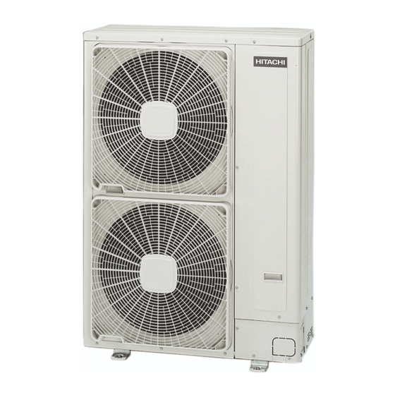
- Page 1 YUTAKI S80 SERIES Technical Catalogue RWH-(4.0-6.0)FS(V)NFE Indoor unit RAS-(4-6)H(V)RNME-AF Outdoor unit DHWS-(195/260)S-2.0H1E DHW tank PC-S80TE LCD controller...
-
Page 3: Contents
Contents C o n t e n t s General information Features and benefits General data Capacities and Selection data Acoustic characteristic curves Working range General dimensions Refrigerant cycle Piping work and refrigerant charge Electrical wiring Installation configurations Optional functions Troubleshooting TCGB0075 rev.0 - 11/2012... -
Page 5: Table Of Contents
General Index Contents ..........................3 1. General information ....................... 9 1.1 General information ..........................10 1.1.1 General notes ..............................10 1.1.2 Introduction ..............................10 1.1.3 Environment-friendly units ..........................11 1.2 Applied symbols ............................12 1.3 Product guide............................13 1.3.1 Product guide ..............................13 1.3.2 ... - Page 6 2.6.2 Flexible Domestic Hot Water (DHW) control ....................47 2.6.3 Swimming pool combination control ......................49 2.6.4 Flexible water pumps control ......................... 49 2.6.5 Other optional functions ..........................49 2.7 Maintenance benefits..........................51 2.7.1 Complete operation display by LCD user’s interface ..................51 2.7.2 Front access to the electrical box ........................51 2.7.3 Easy servicing ............................... 52 2.7.4 High accessibility to the water pressure ports ....................
- Page 7 5. Acoustic characteristic curves ................... 79 5.1 Sound pressure level for outdoor unit ....................... 80 5.1.1 Considerations .............................. 80 5.1.2 Charts ................................81 Working range ......................83 6.1 Working range ............................84 General dimensions ....................85 7.1 Name of parts ............................86 7.1.1 Outdoor unit ..............................
- Page 8 9.3.2 Water piping ..............................110 9.3.3 Water quality..............................112 Electrical wiring ..................... 113 10.1 Unit electrical wiring and connection ....................114 10.1.1 General check ............................114 10.2 Electrical wiring connection ........................116 10.2.1 Outdoor unit terminal board connections ....................116 10.2.2 Indoor unit terminal board connections ......................117 10.3 Printed circuit board (PCB) ........................
-
Page 9: General Information
1. General information G e n e r a l i n f o r m a t i o n Index 1.1. General information ..........................10 1.1.1. General notes ............................10 1.1.2. Introduction ..............................10 1.1.3. Environment-friendly units ..........................11 1.2. -
Page 10: General Information
– as well as for new builds. It is designed for boiler substitution, offering heating and sanitary hot water all year round, without boiler back-up. The YUTAKI S80 is easy to install and operate; it’s a split system, using HITACHI’s IVX outdoor unit with a brand new standalone indoor unit. -
Page 11: Environment-Friendly Units
YUTAKI S80 can also be used to heat up the swimming pool water temperature up to a value between 24 and 33ºC. 1.1.3 Environment-friendly units The new HITACHI’s YUTAKI S80 series uses environmentally-friendly R410A / R134a gas refrigerants, and the RoHS and Green Dot regulations are applied throughout the manufacturing and installation process to reflect HITACHI’s awareness of environmental respect and commitment. -
Page 12: Applied Symbols
1. General information 1.2 Applied symbols During normal air conditioning system design work or unit installation, greater attention must be paid in certain situations requiring particular care in order to avoid damage to the unit, the installation or the building or property. Situations that jeopardise the safety of those in the surrounding area or that put the unit itself at risk will be clearly indicated in this manual. -
Page 13: Product Guide
1. General information 1.3 Product guide 1.3.1 Product guide Outdoor unit Outdoor unit Single phase Three phase (1~ 230V 50Hz) (3N~ 400V 50Hz) Unit Code Unit Code RAS-4HVRNME-AF 7E300020 RAS-4HRNME-AF 7E300120 RAS-5HVRNME-AF 7E300021 RAS-5HRNME-AF 7E300121 RAS-6HVRNME-AF 7E300022 RAS-6HRNME-AF 7E300122 ... - Page 14 LCD controller Unit Code PC-S80TE (*) 7E543001 N O T E (*): For indoor unit alone (without tank) or indoor unit with other tank (non HITACHI tank beside the indoor unit), the LCD controller is needed. TCGB0075 rev.0 - 11/2012...
-
Page 15: Model's Classification
1. General information 1.3.2 Model’s classification Classification of outdoor unit model Unit type: Outdoor unit Position-separating hyphen (fixed) Compressor power (HP): 4, 5, 6. Heat pump V= Single phase unit (1~ 230V 50Hz) - = Three phase unit (3N~ 400V 50Hz) Inverter system R410A refrigerant IVX series... -
Page 16: Accessory Code List
1. General information 1.3.3 Accessory code list Room Thermostats Accessory Name Code Figure ON/OFF Thermostat ATW-RTU-01 7E543000 (Receiver + Room Thermostat) “Intelligent” Thermostat ATW-RTU-02 7E549900 (Receiver + Room Thermostat) 2nd temperature Thermostat ATW-RTU-03 (Only Room Thermostat) 7E549901 *Only for “Intelligent” Thermostat application ... - Page 17 1. General information Accessory Name Code Figure ATW-2KT-01 7E549904 2nd. temperature kit (CDH2Z1) (CDH2Z1) ATW-MVM-01 Mixing valve motor 7E549912 ATW-AQT-01 7E549907 Aquastat (ASMSH1) (ASMSH1) Ambient temperature sensor ATW-2OS-01 7E549909 (2nd. outdoor temperature sensor) ATW-SPS-01 7E549908 Swimming pool sensor Water temperature sensor ATW-WTS-02 7E549911 (Second temperature control)
-
Page 19: Features And Benefits
2. Features and benefits F e a t u r e s a n d b e n e f i t s Index 2.1. Main features............................20 2.2. Selection benefits ..........................21 2.2.1. Environment-friendly system ........................21 2.2.2. Water outlet temperature up to 80 ºC ......................22 2.2.3. -
Page 20: Main Features
6 Floor standing structure with high installation possibilities (Indoor unit alone (without tank), Indoor unit with HITACHI tank (Tank integrated over the indoor unit), Indoor unit with HITACHI tank (Tank beside the indoor unit) and Indoor unit with other tank (Non HITACHI tank beside the indoor unit). -
Page 21: Selection Benefits
As it is known, the solar panels get the heat from the solar radiation, resulting in an environment friendly system. N O T E Not available when the HITACHI domestic hot water tank is integrated over the indoor unit. TCGB0075 rev.0 - 11/2012... -
Page 22: Water Outlet Temperature Up To 80 ºc
YUTAKI S80 is the best solution to replace existing boilers which work on systems with old radiators and weak isolation, or for new installations with very high capacity requirements. For new installations with low capacity requirements the best solution could be YUTAKI S unit. By this way, HITACHI covers the main heating requirements of the market. Water outlet temperature (ºC) -
Page 23: Smart Cascade Cycle
2. Features and benefits 2.2.3 SMART cascade cycle Concept of normal cascade cycle There exist some cycles which could require working at very low evaporation temperatures. For this type of application a single refrigerant is not able to evaporate at low temperatures with positive pressures (higher than 1 atm) and to conden- sate at high temperatures with pressures not too high with a good performance. In this situation it must resort to an installation consisting on two single-stage cycles (high and low temperatures), thermally connected by an intermediate heat exchanger. This cycle is known as cascade cycle. - Page 24 2. Features and benefits Concept of SMART cascade cycle The normal cascade cycle would work continuously using two single-stage cycles; the innovative YUTAKI S80 SMART cascade cycle allows to take advantage of the best possible performance depending on the water outlet temperature re- quired.
-
Page 25: High Efficiency System
2. Features and benefits 2.2.4 High efficiency system The combination of the scroll compressor and the inverter type continuous control, the “smart cascade” system, the high efficiency plate heat exchangers and the water pumps classified as low energy power input allow the maximum energy efficiency, resulting in the highest coefficient of performance (COP) of the market. N O T E Conditions range: - COP: Water inlet / outlet temperature: 30/35 ºC Outdoor Temperature (DB/WB): 7/6 ºC 2.2.5 Wide capacity range The YUTAKI S80 system provides the highest maximum heating capacity of the market at high water outlet temperatures ... -
Page 26: Nominal Heating Capacity Stable At Low Outdoor Ambient Temperatures
2. Features and benefits 2.2.6 Nominal heating capacity stable at low outdoor ambient temperatures The YUTAKI S80 system is able to keep the heating capacity stable at low outdoor ambient temperatures, even for high water outlet temperatures. Therefore, the use of a water electric heater or boiler is highly reduced. Nominal heating capacity (kW) Outdoor ambient... -
Page 27: Advanced Technology
2. Features and benefits 2.2.9 Advanced technology The functionality benefits explained before (Highly efficiency system, wide capacity range, etc.) are direct consequence of the advanced technology applied on all the system components. Then, the main features on different components of the system will be detailed: TCGB0075 rev.0 - 11/2012... - Page 28 2. Features and benefits Outdoor unit heat exchanger High-efficiency heat exchanger • The slitless fin design is adapted to the heat exchanger. As a result, the frosting effect is prevented by the surface of the slitless fin and the heating performance is improved under the low temperature conditions. • Compact design and high-efficiency by arranging narrow heat exchanger tubes in 3 rows. • Heat exchanger configuration aiming at fluid loss reduction. Slitless Fin Slit Fin Side flow technology Energy-saving and uniform air velocity distribution by side flow technology. outlet inlet Air speed (m/s) TCGB0075 rev.0 - 11/2012...
- Page 29 2. Features and benefits Improved performance by subcooling circuit The system performance is improved by enlarged heat transfer area of outdoor unit and subcooler heat exchanger. Front side Rear side Sub-cooler Increase of enthalpy due to the use of the inlet outlet sub-cooling circuit. Fan unit Super high-stream fan The outdoor units have been designed with a new super high-stream fan of Ø544 mm, reducing the sound level and in- creasing its reliability, by the use of a three-blade design propeller.
- Page 30 The switching element (a power MOSFET) switches back and forth at a frequency of several tens of kHz. This controls the ON/OFF duty rate per cycle and changes the voltage applied to the fan motor to control the rotation speed. HITACHI scroll compressors (R410A for the outdoor unit and R134a for the indoor unit) Highly efficient scroll compressor The HITACHI DC INVERTER scroll compressor has been developed to increase efficiency, reliability and to reduce power ...
- Page 31 Volume Lubrication Bearing in mind that lubrication is one of the most important factors in the service life of a compressor, HITACHI has deve- 1. Comercial information loped a system based on the pressure differences between the suction and discharge using a secondary pump at the base of the compressor.
- Page 32 Gas outlet Fixed scroll Moving scroll Housing Medium pressure chamber “Oldham ring” Shaft Oilway Hitachi Air Conditioning Product SA 2008. Optimized design of stator coils The design of the stator coils positioned to optimize the magnetic field significantly reduce heat losses, and increase the motor’s efficiency at low speeds. Compressor efficiency New stator coil design Current model DC compressor with neodymium magnet The use of a DC compressor with neodymium magnets in the rotor improves the performance at around the 30-40Hz range ...
- Page 33 2. Features and benefits Low noise • Inverter control: The inverter controls compressor speeds from 30Hz to 115Hz, quickly reaching the set temperature and maintaining a stable energy-saving operation, thus reducing the noise since the compressor is not running conti- nuously. Setting temperature (in heating mode) Set temperature RAS-H(V)RNME-AF Machine with constant speed Time In the case of RAS-H(V)RNME-AF: Quickly reaches the temperature set at high power, then maintains stable energy-saving operation.
- Page 34 2. Features and benefits Indoor unit heat exchanger (For R410A and R134a) The indoor unit has three heat exchangers: R410A-R134a plate heat exchanger R410A-H2O plate heat exchanger R134a-H2O plate heat exchanger Highly efficiency plate heat exchanger The use of a plate heat exchanger type allows getting high performance due to the following advantages: • High heat transfer surface coefficient, leading to very high values of the heat transfer overall coefficient. • High flow turbulence in the fluids, achieving turbulent regimes for low Reynolds numbers. This high turbulence allows lower circulating speeds on the fluids. • Lower heat losses, since only the edges of the plates are exposed to the outside environment and additionally to having small thicknesses, it can be readily isolated. Water pump Low power consumption The air to water heat pump incorporates a water pump to circulate the water flow into the system.
- Page 35 2. Features and benefits Three different pump motor speeds In order to adapt the flow rate to the system requirements, there are available three pump motor speeds. Example of RWH-6.0FS(V)NFE Viewed from A Pump speed selection Water flow (m N O T E V: Pump motor speed (V : Low, V : Medium, V : High) 3-way valve Quick switching The fast change-over in diverting applications reduces unnecessary energy consumption. This valve is extremely fast: it change from A to B circuit taking only 3 seconds.
- Page 36 2. Features and benefits Domestic hot water tank (optional accessory) The domestic hot water tank is an accessory supplied by HITACHI which allows the domestic hot water production, with the following characteristics: DHWS195S-2.0H1E DHWS260S-2.0H1E Combination flexibility There exist the possibility to install the tank integrated over the indoor unit o beside it. Stainless steel tank Tank models are made in Stainless steel chemically descaled and passivated.
-
Page 37: Installation Benefits
B) Indoor unit with HITACHI tank (Without tank) (Tank integrated over the indoor unit) C) Indoor unit with HITACHI tank D) Indoor unit with other tank (Tank beside the indoor unit) (Non HITACHI tank beside the indoor unit) Depending on the configuration type, the installation procedure will be different. TCGB0075 rev.0 - 11/2012... -
Page 38: Easy Unit Installation
2. Features and benefits 2.3.2 Easy unit installation Easier unit installation due to the following aspects: Compact size • Reduced unit dimensions: Both indoor unit and DHW tank models are 595 mm of width, very suitable for indoor utility room (<600 mm). Indoor unit with integrated tank DHWS195S-2.0H1E is lower than 2m of height. • Steel plate cover: The material used for the service cover improves its rigidity. • ... -
Page 39: Easy And Flexible Electrical Installation
It has been designed a big terminal board (TB2) in order to allow the easy electrical connection which provide all the diffe- rent possible configurations (3-way valve, water pumps, boiler...). Additionally, in order to help with the electrical installation works, HITACHI offers the following specific documentation: Service Manual and Installation and Operation Manual: All the necessary information about how to perform the electrical works (electrical installation, connection, dip switch setting, ...) is reflected in these documents. -
Page 40: Start-Up Benefits
2. Features and benefits 2.4 Start-up benefits 2.4.1 Start-up by pressing the Run/Stop button of LCD user’s interface The unit is factory set to work only by pressing the Run/Stop button of the LCD user’s interface. The default value is set for one circuit (Direct) with OTC gradient for heating space of 1.4, corresponding to a high tempe- rature system (for example, radiators). -
Page 41: Control Features
A user-friendly interface control has been designed to supply as accessory for indoor unit alone (without tank) and integra- ted into the DHW tank for indoor unit with HITACHI tank (Tank integrated over the indoor unit). This controller allows the remote control of the air to water heat pump by using the “Intelligent”... - Page 42 2. Features and benefits Complete display menu (Comprehensive view) Main screen is called “comprehensive view”. It provides the general system information distributed in 4 zones (Circuit I, Circuit II, Domestic Hot Water and swimming pool) through the screen, separating the different working concepts allowing checking the status of each circuit. ...
-
Page 43: Control Features
2. Features and benefits 2.6 Control features 2.6.1 Flexible space heating configuration and control Many available system configurations As mentioned before, YUTAKI S80 allows the control of a large variety of configurations. N O T E For the detailed information, please refer to the section “Installation configurations”. Second water temperature control YUTAKI S80 allows the water temperature control of two zones with different required temperatures (radiators + heating floor for example) by means of the 2nd Temperature Room Thermostat (as accessory). The mixing valve is controlled to maintain the second supply temperature at the second temperature set-point. The system control then decides how much to open or close the mixing valve to achieve the desired position for the valve. Zone 2: Low temperature Second temperature control Secondary To heat pump water pump system control Motorized ... - Page 44 2. Features and benefits Three different possible water temperature set-point configuration modes for each zone • OTC Points: Water target is selected by an Outside Temperature Compensated (OTC) control that is defined by 4 different points (Minimum and maximum water outlet temperature vs Minimum and maximum outdoor ambient tempe- rature). Water outlet temperature Water temperature set-point (ºC) set point ºC Temperature setting at low (44) Tsh ambient temperature Temperature setting at high (20) Tshr ambient temperature Low ambient High ambient...
- Page 45 2. Features and benefits Maximum/minimum water temperature setting for space heating protection by Installer mode • Heating circuit minimum/maximum temperature limits selection by installer: The installer will limit the space heating temperature set-point in order to prevent excessively high or low temperatures. Water outlet temperature Water outlet temperature set-point (ºC) set point ºC Maximum water temperature Maximum water temp Tmaxh Water temperature setting example Example of water temperature setting Tminh Minimum water temp Minimum water temperature Outdoor ambient temperature(ºC) Outdoor ambient temperature (ºC) N O T E...
- Page 46 (*): The input power values shown previously are explained as example for water electric heater supplied for HITACHI as accessory (WEH-6E), with a total input power of 6.0 kW. For water electric heaters of other total input power, the input power for each step will be different.
-
Page 47: Flexible Domestic Hot Water (Dhw) Control
2. Features and benefits 2.6.2 Flexible Domestic Hot Water (DHW) control An optional Domestic Hot Water Tank (DHWT) accessory can be connected to the air to water heat pump in order to provide the Domestic Hot Water operation. The DHWT is available in 2 models stainless steel, with an integrated electric heater of 2.0 kW. - Page 48 DHW by means of the sun. The solar combination is designed to transfer the heat from the solar panels (sun radiation) to the heat exchanger of DHW tank. N O T E Not available when the HITACHI domestic hot water tank is integrated over the indoor unit. TCGB0075 rev.0 - 11/2012...
-
Page 49: Swimming Pool Combination Control
2. Features and benefits 2.6.3 Swimming pool combination control When the swimming pool operation is required, the swimming pool pump starts to operate giving the swimming pool pump feedback. In this situation, the 3-way valve of the DHWT is not activated and the 3-way valve for the swimming pool changes its normal position diverting to the swimming pool heat exchanger, allowing to heat the swimming pool water to ... - Page 50 PCB. N O T E • In order to make easy the electrical connection works, HITACHI offers (as accessory) a relay board for the additional output signals. • For more information about the Optional functions, please refer to the YUTAKI S80 Service Manual.
-
Page 51: Maintenance Benefits
2. Features and benefits 2.7 Maintenance benefits 2.7.1 Complete operation display by LCD user’s interface The LCD user’s interface display menu allows to check all the important parameters and status of the unit in any moment. Most of these variables are the same ones that can be consulted by 7-segment, taking information from the outdoor unit. • ... -
Page 52: Easy Servicing
2. Features and benefits 2.7.3 Easy servicing The YUTAKI S80 design allows that the most important components can be accessible and extracted from the front side of the unit. For example, the electrical box can be easily extracted from the unit’s front side only disconnecting the wire-to- wire connection Top view Front view W i r e - t o - w i r e connections 2.7.4 High accessibility to the water pressure ports Water pressure ports for installation comissioning are accessible only removing the indoor unit front and upper cover. W a t e r pressure ports... -
Page 53: Alarm Hystorical Data
2. Features and benefits 2.7.5 Alarm hystorical data This option is available in order to facilitate a knowledge of the last alarms registered on the LCD user’s interface. The software can save up to the last 20 alarms, showing on the screen the following data: • ... -
Page 55: General Data
3. General data G e n e r a l d a t a Index 3.1. YUTAKI S80 system ..........................56 3.2. Outdoor unit............................57 3.2.1. RAS-(4-6)HVRNME-AF ..........................57 3.2.2. RAS-(4-6)HRNME-AF ..........................58 3.3. Indoor unit ............................. 59 3.3.1. RWH-(4.0-6.0)FSVNFE ..........................59 3.3.2. -
Page 56: Yutaki S80 System
3. General data 3.1 YUTAKI S80 system Indoor unit RWH-4.0FS(V)NFE RWH-5.0FS(V)NFE RWH-6.0FS(V)NFE Model Outdoor unit RAS-4H(V)RNME-AF RAS-5H(V)RNME-AF RAS-6H(V)RNME-AF (Nominal) 10.0 12.0 14.0 Conditions: Water inlet/outlet: 30/35ºC Outdoor temperature: (DB/WB): 7/6 ºC 4.36 4.27 4.05 (Nominal) 10.0 12.0 14.0 Conditions: Water inlet/outlet: 40/45ºC Outdoor temperature: (DB/WB): 7/6 ºC 3.45... -
Page 57: Outdoor Unit
3. General data 3.2 Outdoor unit 3.2.1 RAS-(4-6)HVRNME-AF Model RAS-4HVRNME-AF RAS-5HVRNME-AF RAS-6HVRNME-AF Electrical power supply 1~ 230V 50Hz Color (Munsell code) Natural gray (1.0Y8.5/0.5) Sound pressure level dB(A) Sound power level dB(A) Height 1,380 1,380 1,380 Outside mea- Width surements Depth Net weight Refrigerant R-410A Flow control... -
Page 58: Ras-(4-6)Hrnme-Af
3. General data 3.2.2 RAS-(4-6)HRNME-AF Model RAS-4HRNME-AF RAS-5HRNME-AF RAS-6HRNME-AF Electrical power supply 3N~ 400V 50Hz Color (Munsell code) Natural gray (1.0Y8.5/0.5) Sound pressure level dB(A) Sound power level dB(A) Height 1,380 1,380 1,380 Outside measu- Width rements Depth Net weight Refrigerant R-410A Flow control Microprocessor-controlled expansion valve Compressor... -
Page 59: Indoor Unit
3. General data 3.3 Indoor unit 3.3.1 RWH-(4.0-6.0)FSVNFE Model RWH-4.0FSVNFE RWH-5.0FSVNFE RWH-6.0FSVNFE Electrical power supply 1~ 230V 50Hz Pump input power Maximum current 24.0 28.0 31.0 m³/h Nominal water flow (condition Height 706 (*1) Unit Width dimensions Depth Height Packaging Width dimensions Depth Net weight Packaging dimensions m³... -
Page 60: Rwh-(4.0-6.0)Fsnfe
3. General data 3.3.2 RWH-(4.0-6.0)FSNFE Model RWH-4.0FSNFE RWH-5.0FSNFE RWH-6.0FSNFE Electrical power supply 3N~ 400V 50Hz Pump input power Maximum current 15.0 15.0 15.0 m³/h Nominal water flow (condition Height 706 (*1) Unit Width dimensions Depth Height Packaging Width dimensions Depth Net weight Packaging dimensions m³ 0.46 Refrigerant R-134a... -
Page 61: Domestic Hot Water Tank
3. General data 3.4 Domestic Hot Water Tank Model DHWS195S-2.0H1E DHWS260S-2.0H1E Color White (RAL 9016) Casing Material Stainless steel Separated tank 1272 (*1) 1602 (*1) Height Integrated tank 1940 (*1) 2270 (*1) Unit Width Depth Dimensions Height 1399 1729 Width Packing Depth Volume... -
Page 62: Component Data
3. General data 3.5 Component data 3.5.1 Outdoor unit RAS-(4-6)HVRNME-AF Model RAS-4HVRNME-AF RAS-5HVRNME-AF RAS-6HVRNME-AF Heat exchanger type Multi-pass cross-finned tube Material Copper piping Outer diameter Ømm Piping Rows Number of tubes/coil Material Aluminum Pitch Maximum operating pressure 4.15 4.15 4.15 Total face area 1.35 1.35 1.35 Number of coils/unit Type... - Page 63 3. General data RAS-(4-6)HRNME-AF Model RAS-4HRNME-AF RAS-5HRNME-AF RAS-6HRNME-AF Heat exchanger type Multi-pass cross-finned tube Material Copper piping Outer diameter Ømm Piping Rows Number of tubes/coil Material Aluminum Pitch Maximum operating pressure 4.15 4.15 4.15 Total face area 1.35 1.35 1.35 Number of coils/unit Type Multi-blade centrifugal fan Number/unit Outer diameter Revolutions...
-
Page 64: Indoor Unit
3. General data 3.5.2 Indoor unit Model RWH-4.0FS(V)NFE RWH-5.0FS(V)NFE RWH-6.0FS(V)NFE 1~ 230V 50Hz H405DHD-64A1 H405DHD-64A1 H405DHD-64A1 Model 3N~ 400V 50Hz H405DHD-64D1 H405DHD-64D1 H405DHD-64D1 Type Hermetic scroll Discharge 2.94 2.94 2.94 Pressure resistance Suction 0.15 0.15 0.15 Starting method Inverter-driven (I.D.) Motor type Poles Insulation class Oil type FVC68D FVC68D... -
Page 65: Electrical Data
• RNC: Running current. • MC: Maximum current. • CB: Recommended circuit breaker. • ELB: Earth leakage breaker. N O T E • Heating inlet/outlet water temperature condition: 55/65 ºC. • Outdoor ambient temperature (DB/WB): 7/6 ºC • Specifications in these tables are subject to change without notice in order that HITACHI may bring the latest innovations to their customers. 3.6.2 Outdoor unit Applicable vol- Compressor and fan Max. tage... -
Page 66: Domestic Hot Water Tank - Electrical Heater
3. General data 3.6.4 Domestic Hot Water Tank - Electrical heater Applicable voltage Model Power supply IPT (kW) RNC (A) U max. U min. DHWS195S-2.0H1E 1~ 230V 50Hz DHWS260S-2.0H1E N O T E (*1): If it is desired to enable the DHW tank heater operation during normal indoor unit operation, adjust the DSW4 pin 1 of the PCB1 to the ON position and use these protections: CB=40A for single phase (1~) or CB=25A for three phase (3N~). -
Page 67: Capacity And Selection Data
4. Capacity and selection data C a p a c i t y a n d s e l e c t i o n d a t a Index 4.1. System selection procedure ........................68 4.1.1. Selection parameters ..........................68 4.1.2. -
Page 68: System Selection Procedure
4. Capacity and selection data 4.1 System selection procedure The following procedure gives an example of selection of YUTAKI S80 system based on a series of previously defined installation requirements: heating load required, operating temperatures and special characteristics on the installation (en- ergy system used, power source, etc.). 4.1.1 Selection parameters To calculate the YUTAKI S80 units, it will be necessary to consult and/or use a series of parameters shown in tables and graphics presented in the different chapters of this catalogue. A summarized list is shown below: Available models Maximum heating capacities... - Page 69 4. Capacity and selection data Mono-valent system The YUTAKI S80 is sized to provide 100% of the heating requirements on the coldest day of the year. Example of Mono-valent system N O T E • T : Outdoor ambient temperature. • P : Heating capacity. Air to water heat pump Mono-energy system The YUTAKI S80 is sized to provide approximately 80% of the heating requirements in the coldest days of the year. An auxiliary electric heater (as accessory) is used to provide the additional heating required on cold days. Example of Mono-energy system N O T E • T : Outdoor ambient temperature.
- Page 70 4. Capacity and selection data Procedure description Follow the next selection procedure given in this chapter: a. System combination (outdoor unit + indoor unit) selection i. Without heating source (Mono-valent system) ii. With additional heating source (Mono-energy / Bivalent system) b. It will be selected the domestic hot water tank accessory (optional). a.i) Mono-valent system (regular election) In case of normal selection of Mono-valent system (without additional heating sources) the YUTAKI S80 will be selected depending on the required heating load.
- Page 71 4. Capacity and selection data As it is visible in the table, the YUTAKI S80 system that covers the installation’s heating requirements is the combination of RAS-5HVRNME-AF + RWH-5.0FS(V)NFE. Therefore, this will be the pre-selected YUTAKI S80 system. N O T E In case of working with an ambient temperature value not included in the Maximum heating capacity tables of section Maximum heating capacity...
- Page 72 4. Capacity and selection data a.ii) Use of auxiliary heating source (electric heater or boiler combination) In installations which already have a conventional boiler (gas/oil), it can be used to alternate with YUTAKI S80 (Bi-valent system) which it will help to increase the overall performance of the whole installation significantly. Equally, if an additional heat load is required, an electric heater can be installed as accessory for the Mono-energy system. In any case, the Procedure description explained before can be applied to all the energy systems mentioned but includ- ing a heat load check when using auxiliary heating source (Mono-energy or Bi-valent systems) and recalculating the new ...
- Page 73 4. Capacity and selection data As the heating load has fallen to 9.0 kW as we are considering this point as regular heating load, it may be reselected the needed unit. The RAS-5H(V)RNME-AF + RWH-5.0FS(V)NFE system would provide too much heating capacity so we could take the RAS-4H(V)RNME-AF + RWH-4.0FS(V)NFE system for these new conditions.
- Page 74 Once applied the applicable correction factors, the actual heating capacity provided by the RAS-4H(V)RNME-AF + RWH-4.0FS(V)NFE system is 11.47 kW. This heating capacity does not cover the required heating load for the coldest days (13.0 kW). In these cases, the water electric heater supplied by HITACHI as accessory (WEH-6E) will provide the auxiliary capacity required to cover temporary heating needs. The auxiliary electric heater provides a maximum power of 6.0 kW which must be added to the heating ...
- Page 75 • The storage capacity of the tank has to meet with the daily consumption in order to avoid stagnation of water. • The YUTAKI S80 is designed for combination with HITACHI Domestic Hot Water Tank. In case of another tank is being used in combination with YUTAKI S80, HITACHI cannot guarantee neither good operation or reliability of the system.
-
Page 76: Maximum Heating Capacity Tables
4. Capacity and selection data 4.2 Maximum heating capacity tables Ambient temperature (ºC WB) Water outlet System temp. (ºC) (kW) (kW) (kW) (kW) (kW) (kW) (kW) (kW) (kW) (kW) (kW) (kW) (kW) 11.2 11.7 12.1 12.3 12.5 12.9 13.1 13.5 13.5 13.5 13.5... -
Page 77: Correction Factors
4. Capacity and selection data 4.3 Correction factors 4.3.1 Defrost correction factor The maximum heating capacity shown above does not include operation during frost or defrosting. When this type of operation is taken into account, the heating capacity must be corrected according to the following equa- tion: Correction heating capacity = Correction factor x heating capacity Outdoor inlet air temp. (ºC WB) ≥6 (HR = 85% ) Defrost correction factor f... - Page 78 4. Capacity and selection data Heating piping length correction factor N O T E Take note that the piping length specified in the following graphics is the equivalent piping length (EL), consid- ering the possible elbows, bends... The actual piping length (L) is slightly lower, 30 m. RAS-4H(V)RNME-AF RAS-5H(V)RNME-AF RAS-6H(V)RNME-AF N O T E The heating capacity should be corrected according to the following formula: THA = TH x PH THA: Actual corrected heating capacity (kW) TH: Heating capacity from heating capacity table (kW).
-
Page 79: Acoustic Characteristic Curves
5. Acoustic characteristic curves A c o u s t i c c h a r a c t e r i s t i c c u r v e s Index 5.1. Sound pressure level for outdoor unit ....................80 5.1.1. -
Page 80: Sound Pressure Level For Outdoor Unit
5. Acoustic characteristic curves 5.1 Sound pressure level for outdoor unit 5.1.1 Considerations 1 Distance of the unit from the measuring point: At 1 meter from the unit’s front surface; 1,5 meter from floor level. 2 The data is measured in an anechoic chamber, so reflected sound should be taken into consideration when installing the unit. 3 The sound measured with the curve A shown in dB(A) represents the attenuation in function of frequency as perceived by the human ear. 4 Reference acoustic pressure 0dB=20μPa TCGB0075 rev.0 - 11/2012... -
Page 81: Charts
5. Acoustic characteristic curves 5.1.2 Charts RAS-4HVRNME-AF RAS-5HVRNME-AF Heating Heating Approximate threshold Approximate threshold of continuous noise of continuous noise detection detection Frequency (Hz) Frequency (Hz) Sound pressure level: Heating; 46 dB(A) Sound pressure level: Heating; 48 dB(A) RAS-6HVRNME-AF RAS-4HRNME-AF Heating Heating Approximate threshold Approximate threshold of continuous noise of continuous noise detection... - Page 82 5. Acoustic characteristic curves RAS-5HRNME-AF RAS-6HRNME-AF Heating Heating Approximate threshold Approximate threshold of continuous noise of continuous noise detection detection Frequency (Hz) Frequency (Hz) Sound pressure level: Heating; 48 dB(A) Sound pressure level: Heating; 50 dB(A) TCGB0075 rev.0 - 11/2012...
-
Page 83: Working Range
6. Working range W o r k i n g r a n g e Index 6.1. Working range ............................84 TCGB0075 rev.0 - 11/2012... -
Page 84: Working Range
6. Working range 6.1 Working range Model RWH-4.0FS(V)NFE RWH-5.0FS(V)NFE RWH-6.0FS(V)NFE Water temperature ºC Refer to the graphics for each case Minimum flow rate Maximum flow rate Minimum installation water volume Minimum allowable water pressure Maximum allowable water pressure Indoor temperature installation ºC 5 ~ 35 Space heating Water outlet temperature (ºC) Outdoor ambient... -
Page 85: General Dimensions
7. General dimensions G e n e r a l d i m e n s i o n s Index 7.1. Name of parts ............................86 7.1.1. Outdoor unit ............................... 86 7.1.2. Indoor unit ..............................87 7.1.3. Domestic Hot Water Tank .......................... 88 7.2. -
Page 86: Name Of Parts
7. General dimensions 7.1 Name of parts 7.1.1 Outdoor unit RAS-(4-6)H(V)RNME-AF Units in: mm Part name Remarks Air intake Air outlet Service cover Electrical switch box Holes for refrigerant piping and electrical wiring piping Drain holes 3-Ø24 Drain holes 2-Ø26 Holes for fixing machine to wall 4-(M5) Refrigerant liquid pipe Flare nut: Ø9.53 (3/8”) -
Page 87: Indoor Unit
7. General dimensions 7.1.2 Indoor unit RWH-(4.0-6.0)FS(V)NFE Part name Part name Part name Liquid refrigerant pipe connection Compressor Water pressure switch (ø9.53) Safety valve 13 Check valve Solenoid valves (SV1, SV2) Water pump 14 Expansion vessel Mounting foot (x4) Water strainer 15 Expansion valve (1st cycle) High pressure sensor (Pd) Water flow switch 16 Plate heat exchanger (R410A-H2O) -
Page 88: Domestic Hot Water Tank
7. General dimensions 7.1.3 Domestic Hot Water Tank DHWS-(190/255)S-2.0H1E Part name Part name Part name Domestic hot water tank Manometer Service access Heater + thermostat LCD controller DHW inlet connection (3/4” male) Sensor Front cover DHW outlet connection (3/4” male) Mounting foot (x4) Insulation Heating coil inlet connection (3/4”... -
Page 89: Dimensional Data
7. General dimensions 7.2 Dimensional data N O T E All dimensions in mm. 7.2.1 Outdoor unit RAS-(4-6)H(V)RNME-AF 7.2.2 Indoor unit and domestic hot water tank (optional) N O T E Height dimensions are shown with the minimum mounting foot height. These values can be adjusted up to +30 ... - Page 90 7. General dimensions Indoor unit with HITACHI tank (Tank integrated over the indoor unit) RWH-(4.0-6.0)FS(V)NFE + DHWS190S-2.0H1E RWH-(4.0-6.0)FS(V)NFE + DHWS255S-2.0H1E Indoor unit with HITACHI tank (Tank beside the indoor unit) RWH-(4.0-6.0)FS(V)NFE + DHWS190S-2.0H1E RWH-(4.0-6.0)FS(V)NFE + DHWS255S-2.0H1E TCGB0075 rev.0 - 11/2012...
-
Page 91: Service Space
7. General dimensions 7.3 Service space With the aim to assign the correct space for the unit servicing, it must be taken into account the minimum distances allowed. Depending on the position which the service will be done, it could be required different spaces. 7.3.1 Outdoor unit ... -
Page 92: Indoor Unit And Domestic Hot Water Tank (Optional)
(1): e.box removal available but is recommended > 250 (2) if no space at left side mm for easy servicing Indoor unit with HITACHI tank (Tank integrated over the indoor unit) >30 mm > 30 mm >30 mm > 30 mm... - Page 93 > 250 mm for easy servicing easy servicing Indoor unit with other tank (Non HITACHI tank beside the indoor unit) For Indoor unit service space, refer to the section: Indoor unit alone (Without tank). For non HITACHI tank, see his own technical documentation.
-
Page 95: Refrigerant Cycle And Hydraulic Circuit
8. Refri g erant cycl e and hydraul i c ci r cui t R e f r i g e r a n t c y c l e a n d h y d r a u l i c c i r c u i t Index 8.1. -
Page 96: Ras-(4-6)H(V)Rnme-Af + Rwh-(4.0-6.0)Fs(V)Nfe Combination
8. Refri g erant cycl e and hydraul i c ci r cui t 8.1 RAS-(4-6)H(V)RNME-AF + RWH-(4.0-6.0)FS(V)NFE combination TCGB0075 rev.0 - 11/2012... - Page 97 9. Refrigerant and water piping R e f r i g e r a n t a n d w a t e r p i p i n g Index 9.1. Refrigerant circuit ..........................98 9.1.1. Refrigerant piping ............................. 98 9.1.2.
-
Page 98: Refrigerant Circuit
9. Refrigerant and water piping 9.1 Refrigerant circuit 9.1.1 Refrigerant piping Refrigerant piping length between indoor unit and outdoor unit The refrigerant piping length between indoor unit and outdoor unit should be designed using the following chart. Keep the design point within the area of the chart, which is showing the applicable height difference according to piping length. -
Page 99: Piping Connections
9. Refrigerant and water piping 9.1.2 Piping connections Outdoor unit Refrigerant gas/liquid connection (R410A) of indoor unit are located where it is visible in the following image: Piping work Push down the cover slowly Stop valve Rear cover Rear side piping cover Front side piping cover... -
Page 100: Refrigerant Charge
9. Refrigerant and water piping 9.1.3 Refrigerant charge The YUTAKI S80 has two refrigerant circuits. The R410A circuit (1st cycle) works with this refrigerant while the indoor circuit (2nd cycle) works with R134a refrigerant. Piping connections must be performed in the R410A cycle between the outdoor unit and the indoor unit. - Page 101 9. Refrigerant and water piping Maximum permitted concentration of HFCs The refrigerant R410A, charged in the outdoor unit, and the refrigerant R134a, charged in the indoor unit, are incombustible and non-toxic gases. However, if leakage occurs and gas fills a room, it may cause suffocation. The maximum permissible concentration of HFC gas according to EN378-1 is: Refrigerant Maximum permissible concentration (kg/m R410A 0.44 R134a 0.25 The minimum volume of a closed room where the indoor unit is installed to avoid suffocation in case of leakage is: V >...
-
Page 102: Pump Down Of Refrigerant
9. Refrigerant and water piping 9.1.5 Pump down of refrigerant 1st cycle (R410A) C A U T I O N • To pump down the refrigerant of the R410A cycle (1st cycle) it must be done through the outdoor unit. Refer to the outdoor unit Installation and operation manual for the procedure. -
Page 103: Space Heating Hydraulic Circuit
9. Refrigerant and water piping 9.2 Space heating hydraulic circuit D A N G E R Do not connect the power supply to the indoor unit and DHW tank prior filling of water both circuits and chec- king water pressure and the total absence of any water leak. N O T E The maximum piping length depends on the maximum pressure availability in the water outlet pipe. Please check the pump curves. -
Page 104: Water Piping
9. Refrigerant and water piping 9.2.2 Water piping Water pipes connection Space heating water connection of indoor unit are located where it is visible in the following images: 3-way valve connection T-branch connection for for space heating intlet Space heating outlet 3-way valve T-branch Plastic plug... -
Page 105: Water Quality
9. Refrigerant and water piping 9.2.3 Water quality C A U T I O N • Water quality must be according to EU council directive 98/83 EC. • Water should be subjected to filtration or to a softening treatment with chemicals before application as treated water. • It is also necessary to analyse the quality of water by checking pH, electrical conductivity, ammonia ion con- tent, sulphur content, and others. Should the results of the analysis be not good, the use of industrial water would be recommended. - Page 106 9. Refrigerant and water piping 2 Check the pump performance curves Refer to the Pump Performance Curves (see next chapter Pressure charts) to calculate the circuit’s Water Flow depending on the actual Pressure Drop and the Space heating type (Heating Floor, Radiators, Fan Coils). 3 Selection of the pump speed The indoor unit pump should be adjusted according to Pressure Lost of the circuits and the calculated Water Flow. The pump speed selector switch is located on the pump’s Terminal Box.
-
Page 107: Pressure Charts
9. Refrigerant and water piping 9.2.5 Pressure charts RWH-(4.0-6.0)FS(V)NFE RWH-4.0FS(V)NFE RWH-5.0FS(V)NFE Water flow (m Water flow (m RWH-6.0FS(V)NFE Water flow (m N O T E V: Pump motor speed (V : Low, V : Medium, V : High) TCGB0075 rev.0 - 11/2012... -
Page 108: Domestic Hot Water Hydraulic Circuit (Optional)
9. Refrigerant and water piping 9.3 Domestic Hot Water hydraulic circuit (Optional) D A N G E R Do not connect the power supply to the indoor unit and DHW tank prior filling of water both circuits and chec- king water pressure and the total absence of any water leak. 9.3.1 Hydraulic circuit DHW Tank Nature Part name Security water valve unit (DHWT-SWG-01) Accessories Water check valve (ATW-WCV-01) Recirculation pump... - Page 109 Hydraulic optional elements In case of a recirculation circuit for the DHW circuit: • 1 Recirculation pump (field supplied): this pump (3) will help to correctly recirculate the hot water to the DHW inlet. • 1 Water check valve (ATW-WCV-01 accessory): this Hitachi accessory (2) is connected after the pump (3) in order to ensure the non-return of water. • 2 Shut-off valves (field supplied): one (4) before the pump (3) and one (4) after the check valve (2) in Shut-off valve ...
-
Page 110: Water Piping
9. Refrigerant and water piping 9.3.2 Water piping Water pipes connection Indoor unit connections The domestic hot water connections of indoor unit are located where it is visible in the following images: 3-way valve connection T-branch connection for for heating coil inlet heating coil outlet 3-way valve T-branch... - Page 111 9. Refrigerant and water piping Piping size (mm (inches)) Heating coil From DHW insta- To DHW installa- From indoor unit To indoor unit llation tion DHWS-(195/260)S-2.0H1E Ø19.05 (3/4”) Ø19.05 (3/4”) Ø19.05 (3/4”) Ø19.05 (3/4”) Heating coil and DHW pipes (factory supplied) The DHW tank is factory supplied with two water pipes (heating coil pipes) to connect with the indoor unit (to the T-branch and to the 3-way valve) and other two (DHW pipes) for connection with the DHW installation.
-
Page 112: Water Quality
9. Refrigerant and water piping 9.3.3 Water quality C A U T I O N • Water quality must be according to EU council directive 98/83 EC. • Water should be subjected to filtration or to a softening treatment with chemicals before application as treated water. • It is also necessary to analyse the quality of water by checking pH, electrical conductivity, ammonia ion con- tent, sulphur content, and others. Should the results of the analysis be not good, the use of industrial water would be recommended for the heating coil circuit. -
Page 113: Electrical Wiring
10. Electrical wiring E l e c t r i c a l w i r i n g Index 10.1. Unit electrical wiring and connection ....................114 10.1.1. General check ............................114 10.2. Electrical wiring connection ......................... 116 10.2.1. Outdoor unit terminal board connections ....................116 10.2.2. -
Page 114: Unit Electrical Wiring And Connection
2 Following the Council Directive 2004/108/EC(89/336/EEC), relating to electromagnetic compatibility, next table indi- cates: Maximum permissible system impedance Zmax at the interface point of the user’s supply, in accordance with EN61000-3-11. Outdoor unit (Ω) (Ω) (Ω) Model RAS-4HVRNME-AF 0.41 Indoor unit alone Indoor unit with (Without tank) HITACHI tank RAS-5HVRNME-AF 0.32 RAS-4HVRNME-AF 0.31 0.19 RAS-6HVRNME-AF 0.32 RAS-5HVRNME-AF 0.27 0.19 RAS-4HRNME-AF RAS-6HVRNME-AF 0.24 0.19... - Page 115 10. Electrical wiring C A U T I O N • Check to ensure that screws for terminal block are tightly tightened. • Check to ensure that the indoor fan (inverter box) and the outdoor fan have stopped before electrical wiring work or periodical check is performed.
-
Page 116: Electrical Wiring Connection
10. Electrical wiring 10.2 Electrical wiring connection 10.2.1 Outdoor unit terminal board connections RAS-(4-6)HVRNME-AF RAS-(4-6)HRNME-AF Power Transmission Earth terminal wires wires Earth Power Transmission terminal wires wires 1~ 230V 50Hz 3N~ 400V 50Hz TCGB0075 rev.0 - 11/2012... -
Page 117: Indoor Unit Terminal Board Connections
10. Electrical wiring 10.2.2 Indoor unit terminal board connections Mark Part name Description TERMINAL BOARD 1 (TB1) 1~ 230V 50Hz 3N~ 400V 50Hz TERMINAL BOARD 2 (TB2) Indoor/Outdoor commuta- The H-LINK transmission between outdoor unit and indoor unit is wired to tion cables terminals 1-2. -
Page 118: Printed Circuit Board (Pcb)
10. Electrical wiring 10.3 Printed circuit board (PCB) 10.3.1 Outdoor unit RAS-(4-6)H(V)RNME-AF Connector indication Switch indication PCN1 Fuse DSW1 Test run (PCB1) PCN2 PCB1 connection from outdoor to indoor unit DSW2 Piping length and selection function PCN5 Crankcase heater of compressor (oil) DSW3 Capacity code PCN6... -
Page 119: Indoor Unit
10. Electrical wiring 10.3.2 Indoor unit PCB1 PCB2 Connector Indications PCB1 Name Connector Nº Power supply PCN1 Devices power supply PCN2 Power Input transformer power supply (230v) PCN3A,B Ouput transformer power supply (24v) CN10A,B LCD Power supply CN15 Protection Low Water Pressure & Water Flow control PCN10-1 Device H-Link communication... - Page 120 10. Electrical wiring PCB3 PCB4 Switch indication Connector Indications PCB3 PCB3 Name Connector No. Name Connector Nº Not used DSW1 Power supply PCN1 Capacity Setting DSW2 Devices power supply PCN2 Not used DSW3 Power Input transformer power supply (230v) PCN3A,B Additional setting DSW4 Output transformer power supply (24v)
-
Page 121: Setting Of Dip Switches And Rsw Switches
10. Electrical wiring 10.4 Setting of DIP switches and RSW switches 10.4.1 Outdoor unit Location of DIP switches and RSW switches The PCB in the outdoor unit is operated with different dip switches, rotary switches and push switches. Position switches at the PCB: RAS-(4-6)H(V)RNME-AF SEG1 DSW6... - Page 122 10. Electrical wiring DSW2: Piping length/selection function Function Setting position Setting before shipment 5 m < Lt Piping length 5 m < Lt < 30 m Cancellation of outdoor hot start control. (Not recommended, only available for special testing cases) Cancellation of outdoor air temperature control. (No change) Optional function selection setting (set by PSW) External input/output selection signals (set by PSW) C A U T I O N...
- Page 123 10. Electrical wiring DSW4/RSW1: Refrigerant cycle setting (No change) Setting position (DSW4) Setting position (RSW1) Setting for tens Setting for units (second digit) (first digit) Rotary switches’ positions (RSW1) are set by inserting a screw driver into the groove. DSW5: Transmission setting of end terminal resistance Before shipment, No.
-
Page 124: Indoor Unit
10. Electrical wiring 10.4.2 Indoor unit Location of DIP switches and RSW switches Below are the dip switch positions: Upper side shows unit status Lower side shows unit status 2 Status indication. Press PSW2 more than 3 seconds to change the status display mode ... - Page 125 10. Electrical wiring DSW2: Capacity setting ¡ No setting is required. RWH-4.0FS(V)NFE RWH-5.0FS(V)NFE RWH-6.0FS(V)NFE DSW3: Optional functions 1 ¡ Factory setting 1 step heater for 3 phase unit DSW4: Optional functions 2 ¡ Factory setting Optional functions enabled Heater Forced OFF Unit and installation pipes antifreeze protection C A U T I O N • Never turn all DSW4 dip switch pins...
- Page 126 10. Electrical wiring DSW5: Additional setting 2 ¡ In the cases where the outdoor unit is installed into a location where its own outdoor ambient temperature sensor can not give a suitable temperature measurement to the system, it is available the 2nd outdoor ambient temperature sensor as accessory.
- Page 127 10. Electrical wiring PCB3 DSW1: Not used ¡ Factory setting (Not change) DSW2: Capacity setting ¡ No setting is required. RWH-4.0FS(V)NFE RWH-5.0FS(V)NFE RWH-6.0FS(V)NFE DSW3: Not used ¡ Factory setting (Not change) DSW4: Additional setting ¡ Single phase Three phase (1~ 230V 50Hz) (3N~ 400V 50Hz) Factory setting (Not change)
- Page 128 10. Electrical wiring DSW7: Unit control configuration ¡ Single phase Three phase (1~ 230V 50Hz) (3N~ 400V 50Hz) Factory setting DSW8: Pressure device setting 1 ¡ Factory setting (Not change) DSW9: Pressure device setting 2 ¡ Factory setting (Not change) RSW1 &...
- Page 129 10. Electrical wiring Led indications PCB1 Name Color Indication LED1 Green Pump operation LED2 Green System heater or boiler operation LED3 Green DHW tank’s heater operation LED4 Heat pump operation (thermo ON/OFF) LED5 Yellow Operation: indicates power supply to the unit LED6 Alarm (flickering with 1 sec interval) LED7...
-
Page 130: Common Wiring
10. Electrical wiring 10.5 Common wiring 10.5.1 Electrical wiring between indoor and outdoor unit of the air to water heat pump system • Connect the electrical wires between the indoor unit and the outdoor unit, as shown in the next diagram. • Use twist pair wires (more than 0.75 mm²) for operation wiring between outdoor unit and indoor unit. • ... - Page 131 10. Electrical wiring Recommended minimum sizes for field provided wires N O T E • Follow local codes and regulations when selecting field wires, circuit breakers and earth leakage breakers. • Use the wires which are not lighter than the ordinary polychloroprene sheathed flexible cord (code designation H05RN-F). • (*1): The DHW tank heater is intended to be used in case of indoor and/or outdoor unit malfunction. If the DHW tank heater is enabled during the indoor unit operation, CB and ELB could switch off. If it is desired to enable the DHW tank heater operation during normal indoor unit operation, adjust the DSW4 pin 1 of the PCB1 to the ON position and consider the protections as indicated in “Indoor unit + DHW tank heater combination” on the table.
- Page 132 10. Electrical wiring Main switch protection Outdoor unit Applicable voltage Max. Current Model Power supply CB (A) (no. of poles/A/mA) U max. (V) U min. (V) RAS-4HVRNME-AF 18.0 1~230V 50Hz 2/40/30 RAS-5HVRNME-AF 23.0 RAS-6HVRNME-AF 23.0 RAS-4HRNME-AF RAS-5HRNME-AF 3N~400V 50 Hz 11.0 4/40/30 RAS-6HRNME-AF 13.0 MC: Maximum current; CB: Circuit breaker; ELB: Earth leakage breaker...
-
Page 133: Electrical Wiring Between Dhw Tank And Indoor Unit
10. Electrical wiring 10.5.2 Electrical wiring between DHW tank and indoor unit The supplied wires for the connection between the DHW tank and the indoor unit are as follows: LCD connection cable Electric heater connection cable Rear Ebox Thermistor connection cable ... -
Page 135: Installation Configuration
11. Installation configuration I n s t a l l a t i o n c o n f i g u r a t i o n Index 11.1. System configurations ......................... 136 11.2. Installation configurations ........................138 11.2.1. Main configurations ..........................139 11.2.2. Additional combinations ........................... 142 TCGB0075 rev.0 - 11/2012... -
Page 136: System Configurations
11. Installation configuration 11.1 System configurations The YUTAKI S80 will generate hot water up to 80ºC and it is ideal for existing properties, in particular older establishments where higher water supply temperatures may be required to keep the house warm – as well as for new builds. It is designed for boiler substitution, offering heating and sanitary hot water all year round, without boiler back-up. The YUTAKI S80 is designed to work in a mono-valent, mono-energetic or bi-valent heating systems. It provides efficient ... - Page 137 11. Installation configuration Alternating Bi-valent system The boiler is configured to alternate with the split air to water heat pump. A hydraulic separator of buffer tank has to be used to ensure hydraulic balancing. Example of Alternating Bi-valent system N O T E • T : Outdoor ambient temperature (ºC). • P : Heating capacity. • Bivalent point can be set through the LCD user’s interface. Air to water heat pump TCGB0075 rev.0 - 11/2012...
-
Page 138: Installation Configurations
11. Installation configuration 11.2 Installation configurations N O T E • The following installation examples show typical configurations. In case of variations of them, the responsabi- lity of correct system functioning will be of the installer. • The configuration examples given below are only for illustration purposes. Heating Space heating complement Solar Kit Swim- Tank Thermostat Type Description (field su- ming Electric (acces- (optional) Radiator/ pplied) pool Floor... -
Page 139: Main Configurations
11. Installation configuration 11.2.1 Main configurations One space heating only (Installation example 1) One space heating only: Space heating using radiators or fan coils with an optional room thermostat. The necessary LCD controller is supplied as accessory. Item Description High temperature (80ºC) Outdoor unit Indoor unit R134a compressor... - Page 140 11. Installation configuration Two space heating (High & Low water temperature) (Installation example 3) Two space heating (High & Low water temperature): When the split air to water heat pump is connected to two different heating circuits, circuit 1 will be direct (high temperature for radiator operation) and circuit 2 will be a mixing circuit in order to have a second temperature control using mixing valve motor (low temperature for floor heating operation).
- Page 141 11. Installation configuration Two space heating (High & Low water temperature) and DHW Tank (Installation example 4) Two space heating applications (High & Low water temperature) and DHW Tank: When the split air to water heat pump is connected to two different heating circuits, circuit 1 will be direct (high temperature for radiator operation) and circuit 2 will be a mixing circuit in order to have a second temperature control using mixing valve motor (low temperature for floor hea- ting operation).
-
Page 142: Additional Combinations
11. Installation configuration 11.2.2 Additional combinations Electric heater complement (Installation example 5) Two space heating applications (High & Low water temperature) + Combination with Electric heater + optional Domestic Hot Water Tank: Two space heating application with a Room Thermostat as an option heated by Heat Pump and supple- mented by 3-stage electrical heater (as accessory) to provide additional heating capacity to the system (mono-energetic system). - Page 143 11. Installation configuration Boiler complement (Installation example 6) Installation with alternating space heating and Boiler combination + optional Domestic Hot Water Tank: Space heating application with optional Room Thermostat heated alternating Heat Pump and boiler combination. Optional Domestic Hot Water Tank is heated by Heat Pump. The LCD is integrated with the DHW Tank or supplied as accessory if indoor unit is alone.
- Page 144 N O T E Solar combination is not available when the HITACHI domestic hot water tank is integrated over the indoor unit. Two space heating applications (High & Low water temperature) + Domestic Hot Water Tank + Solar combination + Heating complement (Boiler or Electric heater combination): Two space heating application with a Room Thermostat as an option heated by Heat Pump and alternating boiler or supplemented by 3-stage electrical heater.
- Page 145 11. Installation configuration Swimming pool combination (Installation example 8) Two space heating applications (High & Low water temperature) + optional Domestic Hot Water Tank + Swimmping pool combination + Heating complement (Boiler or Electric heater combination): Two space heating application with a Room Thermostat as an option and swimming pool space heated by Heat Pump and alternating boiler or supplemented by 3-sta- ge electrical heater.
-
Page 147: Optional Functions
12. Optional functions O p t i o n a l f u n c t i o n s Index 12.1. Indoor unit ............................148 12.1.1. Optional functions ............................ 148 12.1.2. Optional external output signals (by 7-segment display) ................. 149 12.2. Outdoor unit............................149 12.2.1. Optional functions ............................ 149 TCGB0075 rev.0 - 11/2012... -
Page 148: Indoor Unit
PCB. N O T E Available four external outputs signals In order to make easy the electrical connection works, HITACHI offers as accessory a relay board for the additional output signals (Auxiliary output signal box ATW-AOS-01). -
Page 149: Optional External Output Signals (By 7-Segment Display)
12. Optional functions 12.1.2 Optional external output signals (by 7-segment display) Unit switches to this mode when DSW4-8 is turned ON during unit stoppage. The unit has the following described optional signals: Code Name Description Port This signal allows control of the machine status at all times; it is very useful Operation signal for centralized applications. -
Page 151: Troubleshooting
13. Troubleshooting T r o u b l e s h o o t i n g Index 13.1. Troubleshooting procedure by alarm code ..................152 13.1.1. Alarm display ............................152 13.1.2. Alarm codes ............................. 153 TCGB0075 rev.0 - 11/2012... -
Page 152: Troubleshooting Procedure By Alarm Code
13. Troubleshooting 13.1 Troubleshooting procedure by alarm code 13.1.1 Alarm display Alarm code indication on LCD controller Alarm code Alarm indication Alarm code indication on 7 segment Indoor unit Position of the 7 segment at the indoor PCB1&3: RWH-(4-6)FS(V)NFE • ... -
Page 153: Alarm Codes
13. Troubleshooting 13.1.2 Alarm codes LCD dis- 7 segment Origin Detail of abnormality Main factors play display Activation of outdoor unit protection device Outdoor High pressure interrupting device activated (Except for alarm code 42) Outdoor - Outdoor fuse meltdown, Indoor/outdoor con- Transmission error 1st cycle nection wiring (breaking, wiring error, etc.) Control PCB –... - Page 154 13. Troubleshooting LCD dis- 7 segment Origin Detail of abnormality Main factors play display Abnormality of fan motor protection (DC fan Outdoor motor) Inverter fin temperature thermistor abnor- Loose, disconnected, broken or short-circuited Outdoor mality connector Comuni- Transmission error between central and Indoor fuse meltdown, indoor/central connec- cation indoor communication tion wiring (breaking, wiring error, etc.)
- Page 155 13. Troubleshooting LCD dis- 7 segment Origin Detail of abnormality Main factors play display Wrong settings are performed in DIP switches 2nd cycle Incorrect PCB Setting on PCB. Wrong settings are performed in DIP switch on 2nd cycle Incorrect operation PCB or prohibited operation is performed.
- Page 158 Hitachi Air Conditioning Products Europe, S.A. Ronda Shimizu, 1 - Políg. Ind. Can Torrella 08233 Vacarisses (Barcelona) España Hitachi certifies that our products have met EU consumer safety, health and environmental requirements. Hitachi Air Conditioning Products Europe, S.A. is certified with:...