
Related Manuals for Siemens 8MF2000


Summary of Contents for Siemens 8MF2000
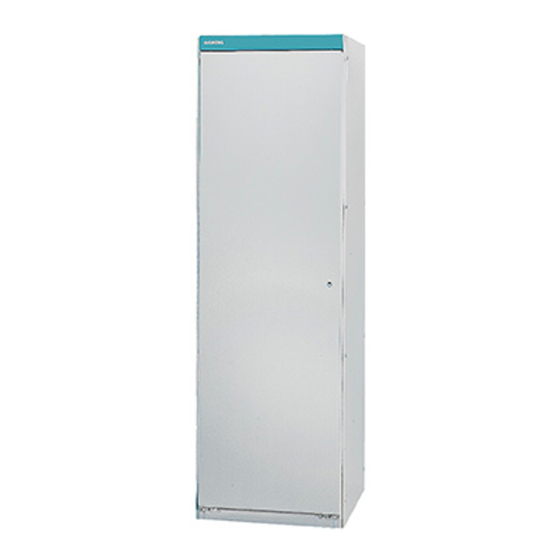
- Page 1 Schranksystem 8MF2000 Cabinet System DIN EN 50298: 1998-04 Deutsch Betriebsanleitung / Operating Instructions Bestell-Nr. / Order No.: A5E00721185 Last update: 02 December 2005...
-
Page 2: Montage
Eine sichere Gerätefunktion ist nur mit zertifizierten Komponenten gewährlei- stet. Anwendungsbereich Das Schranksystem 8MF2000 eignet sich für den Einbau von Geräten und Ein- richtungen der elektronischen und konventionellen Steuerungs- und Regelungs- technik, Mess- und Prozesstechnik, Schutztechnik, Kommunikationstechnik sowie für Niederspannungs-Schaltanlagen. - Page 3 Bodenblech befestigen 1 Die Haltewinkel mit Gewindebolzen M 8x15, Kontaktscheibe 8 und Sechs- kantmutter M 8 an dem hochstehenden Innenschenkel der vorderen und hin- teren Querholme verschrauben, siehe Bild 6. Die obere Fläche des Haltewinkels und die Oberkante des Querholmschenkels müssen in einer Ebene liegen.
- Page 4 Loch (ab Schrankbreite 900 mm) verschrauben, siehe Bild 8b. Bild 9 Tür einbauen Eine 8MF2000 Tür hat 3 Haltepunkte auf der Scharnierseite und 3 auf der Schließstangenseite für Links- bzw. Rechtsanschlag. 1 Bei loser Lieferung von Türen muss der Türwinkel auf der Scharnierseite und die Befestigung des Schließblechs am Schloss mit einberechnet werden, sie-...
- Page 5 Zierblende montieren Schutzmaßnahmen am Gerüst 1 Die Zierblende auf die oberen Türlagerwinkel legen, siehe Bild 11. Der Schutzleiteranschluss der Anlage ist bis zu einer maximalen Absicherung 2 Die Zierblende mit Flachkopfschrauben M 5x17 in dem mittleren Loch der von 630 A der Einspeisung geeignet und muss mit drei Einziehbolzen M 8x15, beiden äußeren Türlagerwinkel angeschrauben.
- Page 6 Reliable functioning of the equipment is only ensured with certified components. Areas of application The 8MF2000 cabinet system is suited for the installation of electronic and conventional control and automatic control systems, measuring and process control systems, safety systems, communication systems as well as low-voltage switchgear system devices and equipment.
- Page 7 Mounting the bottom plate 1 Bolt the mounting angles to the vertical inner leg of the front and back cross members using M 8x15 threaded bolts, 8 contact washers and M 8 hexagonal nuts. See Figure 6. The front surface of the mounting angle and the upper edge of the cross member leg must be on the same plane.
- Page 8 Fig. 9 Installing the door The 8MF2000 door has 3 stop points on the hinge side and 3 on the locking rod side to be used as left-side or right-side end stops. 1 When the doors are delivered unmounted, the door angle on the hinge side and the steel bracket mounting on the lock must be taken into consideration.
- Page 9 Mounting the trimstrip Measures to protective the frame 1 Place the trimstrip on the upper door support angles according to Figure 11. The protective conductor connection of the system is suitable for a maximum 2 Screw the trimstrip into the center hole of the two outer door support angles infeed of 630 A and must be mounted to the frame using three 8x15 draw-in using M 5x17 pan head screws.
- Page 10 Telephone: +49 (0) 180 50 50 222 Technische Änderungen vorbehalten. Zum späteren Gebrauch aufbewahren. Bestell-Nr./Order No.: A5E00721185 Subject to change without prior notice. Store for use at a later date. Printed in the Federal Republic of Germany © Siemens AG 2005...