ABB Relion 670 Series Product Manual
Bay control
Hide thumbs
Also See for Relion 670 Series:
- Technical manual (1432 pages) ,
- Technical reference manual (1232 pages) ,
- Applications manual (944 pages)
Table of Contents
Quick Links
Table of Contents

Related Manuals for ABB Relion 670 Series


Summary of Contents for ABB Relion 670 Series
- Page 1 ® Relion 670 SERIES Bay control REC670 Version 2.2 Product guide...
-
Page 2: Table Of Contents
The information in this document is subject to change without notice and should not be construed as a commitment by Hitachi Power Grids. Hitachi Power Grids assumes no responsibility for any errors that may appear in this document. Drawings and diagrams are not binding. ABB is a registered trademark of ABB Asea Brown Boveri Ltd. -
Page 3: Document Revision History
Bay control REC670 1MRK 511 404-BEN N Version 2.2 Issued: September 2020 Revision: N 1. Document revision history GUID-34B323E4-1319-4D42-80CE-29B0F2D36E2C v4 Table 1. Document revision history Document Date Product revision History revision 2017-07 2.2.0 First release for product version 2.2 2017-10 2.2.1 Ethernet ports with RJ45 connector added. -
Page 4: Application
Bay control REC670 1MRK 511 404-BEN N Version 2.2 Disturbance recording and fault locator are available to allow independent post-fault analysis after primary 2. Application disturbances in case of a failure in the protection M13637-3 v14 The Intelligent Electronic Device (IED) is used for the system. - Page 5 Bay control REC670 1MRK 511 404-BEN N Version 2.2 Optional functions are available in PCM600 Application need to be applied as required for each application. The Configuration Tool and can be configured by the user. main differences between the packages above are the Interface to analog and binary IO:s are configurable interlocking modules and the number of apparatuses to without need of configuration changes.
- Page 6 Bay control REC670 1MRK 511 404-BEN N Version 2.2 Description of configuration A30 M15200-3 v8 REC670 A30 – Double busbar in single breaker arrangement 12AI (6I + 6U) Control Control Control Control Control Control S CILO S CILO S CSWI S CSWI S XSWI S XSWI...
- Page 7 Bay control REC670 1MRK 511 404-BEN N Version 2.2 Description of configuration B30 M15200-12 v6 REC670 B30 - Double breaker arrangement 12AI (6I + 6U) Control Control Control Control Control Control S CILO S CILO S CSWI S CSWI S XSWI S XSWI WA2_VT Control...
- Page 8 Bay control REC670 1MRK 511 404-BEN N Version 2.2 Description of configuration C30 M15200-24 v6 REC670C30 – Complete one-and a half breaker diameter arrangement 24AI (6I + 6U, 6I+6U) Control Control Control Control Control Control S CILO S CILO S CSWI S CSWI S XSWI S XSWI...
- Page 9 Bay control REC670 1MRK 511 404-BEN N Version 2.2 Description of configuration D30 GUID-15D86A4C-4D37-432E-8DC2-518814830097 v2 REC670 D30 – Double busbar in single breaker arrangement with PMU functionality 12AI (6I + 6U) Control Control Control Control Control Control S CILO S CILO S CSWI S CSWI S XSWI...
-
Page 10: Available Functions
Bay control REC670 1MRK 511 404-BEN N Version 2.2 3. Available functions GUID-F5776DD1-BD04-4872-BB89-A0412B4B5CC3 v1 The following tables list all the functions available in the IED. Those functions that are not exposed to the user or do not need to be configured are not described in this manual. - Page 11 Bay control REC670 1MRK 511 404-BEN N Version 2.2 Back-up protection functions GUID-A8D0852F-807F-4442-8730-E44808E194F0 v16 IEC 61850 or ANSI Function description Bay control function name REC670 (Customized) Current protection PHPIOC Instantaneous phase overcurrent 1-C51 2-C52 2-C53 1-C51 protection OC4PTOC Directional phase overcurrent 1-C51 2-C52 2-C53...
-
Page 12: Unbalance Protection
Bay control REC670 1MRK 511 404-BEN N Version 2.2 IEC 61850 or ANSI Function description Bay control function name REC670 (Customized) ROV2PTOV Residual overvoltage protection, two 2-D02 2-D02 2-D02 2-D02 steps VDCPTOV Voltage differential protection LOVPTUV Loss of voltage check Unbalance protection SCCFPVOC Cascading failure protection for shunt... - Page 13 Bay control REC670 1MRK 511 404-BEN N Version 2.2 Control and monitoring functions GUID-E3777F16-0B76-4157-A3BF-0B6B978863DE v20 IEC 61850 or ANSI Function description Bay control function name REC670 (Customized) Control SESRSYN Synchrocheck, energizing check and synchronizing SMBRREC Autorecloser 1-H04 2-H05 3-H06 1-H04 APC10 Control functionality for a single bay, max 10 objects...
-
Page 14: Secondary System Supervision
Bay control REC670 1MRK 511 404-BEN N Version 2.2 IEC 61850 or ANSI Function description Bay control function name REC670 (Customized) SPC8GAPC Single point generic control function 8 signals AUTOBITS Automation bits, command function for DNP3.0 SINGLECMD Single command, 16 signals I103CMD Function commands for IEC... - Page 15 Bay control REC670 1MRK 511 404-BEN N Version 2.2 IEC 61850 or ANSI Function description Bay control function name REC670 (Customized) TMAGAPC Trip matrix logic ALMCALH Logic for group alarm WRNCALH Logic for group warning INDCALH Logic for group indication AND, GATE, INV, Basic configurable logic 40-420...
- Page 16 Bay control REC670 1MRK 511 404-BEN N Version 2.2 IEC 61850 or ANSI Function description Bay control function name REC670 (Customized) TEIGAPC Elapsed time integrator with limit transgression and overflow supervision INTCOMP Comparator for integer inputs REALCOMP Comparator for real inputs Hitachi Power Grids ©...
- Page 17 Bay control REC670 1MRK 511 404-BEN N Version 2.2 IEC 61850 or ANSI Function description Bay control function name REC670 (Customized) Monitoring CVMMXN Power system measurement CMMXU Current measurement VMMXU Voltage measurement phase-phase CMSQI Current sequence measurement VMSQI Voltage sequence measurement VNMMXU Voltage measurement...
- Page 18 Bay control REC670 1MRK 511 404-BEN N Version 2.2 IEC 61850 or ANSI Function description Bay control function name REC670 (Customized) I103AR Function status auto- recloser for IEC 60870-5-103 I103EF Function status earth-fault for IEC 60870-5-103 I103FLTPROT Function status fault protection for IEC 60870-5-103 I103IED...
- Page 19 Bay control REC670 1MRK 511 404-BEN N Version 2.2 Table 3. Total number of instances for basic configurable logic blocks Basic configurable logic block Total number of instances GATE PULSETIMER RSMEMORY SRMEMORY TIMERSET Table 4. Number of function instances in APC10 Function name Function description Total number of instances...
- Page 20 Bay control REC670 1MRK 511 404-BEN N Version 2.2 Table 5. Number of function instances in APC15 Function name Function description Total number of instances SCILO Interlocking BB_ES A1A2_BS A1A2_DC ABC_BC BH_CONN BH_LINE_A BH_LINE_B DB_BUS_A DB_BUS_B DB_LINE ABC_LINE AB_TRAFO SCSWI Switch controller SXSWI Circuit switch...
- Page 21 Bay control REC670 1MRK 511 404-BEN N Version 2.2 Table 6. Number of function instances in APC30 Function name Function description Total number of instances SCILO Interlocking BB_ES A1A2_BS A1A2_DC ABC_BC BH_CONN BH_LINE_A BH_LINE_B DB_BUS_A DB_BUS_B DB_LINE ABC_LINE AB_TRAFO SCSWI Switch controller SXSWI Circuit switch...
- Page 22 Bay control REC670 1MRK 511 404-BEN N Version 2.2 Table 8. Total number of instances for extended logic package Extended configurable logic block Total number of instances GATE PULSETIMER RSMEMORY SLGAPC SRMEMORY TIMERSET VSGAPC Hitachi Power Grids © Copyright 2017 Hitachi Power Grids. All rights reserved...
- Page 23 Bay control REC670 1MRK 511 404-BEN N Version 2.2 Communication GUID-5F144B53-B9A7-4173-80CF-CD4C84579CB5 v18 IEC 61850 or ANSI Function description Bay control function name REC670 (Customized) Station communication LONSPA, SPA SPA communication protocol LON communication protocol HORZCOMM Network variables via LON PROTOCOL Operation selection between SPA and IEC60870-5-103 for SLM RS485PROT...
- Page 24 Bay control REC670 1MRK 511 404-BEN N Version 2.2 IEC 61850 or ANSI Function description Bay control function name REC670 (Customized) GOOSEVCTRCONF GOOSE VCTR configuration for send and receive ALGOS Supervision of GOOSE subscription MULTICMDRCV, Multiple command and transmit 60/10 60/10 60/10 60/10...
- Page 25 Bay control REC670 1MRK 511 404-BEN N Version 2.2 IEC 61850 or ANSI Function description Bay control function name REC670 (Customized) SCHLCCH Access point diagnostic for non- redundant Ethernet port RCHLCCH Access point diagnostic for redundant Ethernet ports DHCP DHCP configuration for front access point QUALEXP IEC 61850 quality expander...
- Page 26 Bay control REC670 1MRK 511 404-BEN N Version 2.2 IEC 61850 or ANSI Function description Bay control function name REC670 (Customized) ZCRWPSCH Current reversal and weak-end infeed 1-K01 1-K01 1-K01 1-K01 logic for distance protection ZCLCPSCH Local acceleration logic 1-K01 1-K01 1-K01 1-K01...
- Page 27 Bay control REC670 1MRK 511 404-BEN N Version 2.2 Basic IED functions GUID-C8F0E5D2-E305-4184-9627-F6B5864216CA v14 Table 10. Basic IED functions IEC 61850 or function Description name INTERRSIG Self supervision with internal event list SELFSUPEVLST TIMESYNCHGEN Time synchronization module BININPUT, SYNCHCAN, Time synchronization SYNCHGPS, SYNCHCMPPS, SYNCHLON,...
- Page 28 Bay control REC670 1MRK 511 404-BEN N Version 2.2 Table 10. Basic IED functions, continued IEC 61850 or function Description name ALTMS Time master supervision ALTIM Time management CAMCONFIG Central account management configuration CAMSTATUS Central account management status TOOLINF Tools information COMSTATUS Protocol diagnostic Table 11.
- Page 29 Bay control REC670 1MRK 511 404-BEN N Version 2.2 depending on the type of the fault and the selected auto • Block/deblock of operation reclosing mode. • Block/deblock of updating of position indications • Substitution of position indications Several auto reclosing functions can be provided for •...
- Page 30 Bay control REC670 1MRK 511 404-BEN N Version 2.2 • Busbar earthing switch, BB_ES node sent over process bus via GOOSE. The GOOSE XLN • Double CB Bay, DB_BUS_A, DB_LINE, DB_BUS_B Receive component includes 12 different outputs (and • 1 1/2-CB diameter, BH_LINE_A, BH_CONN, BH_LINE_B their respective channel valid bits) with defined names to ease the 61850 mapping of the GOOSE signals in the configuration process.
- Page 31 Bay control REC670 1MRK 511 404-BEN N Version 2.2 are used extensively by utilities, in order to have different functions operating on pre-set values. 5. Differential protection Hardware switches are however sources for maintenance issues, lower system reliability and an High impedance differential protection, single phase extended purchase portfolio.
- Page 32 Bay control REC670 1MRK 511 404-BEN N Version 2.2 clients (synchrophasor client). This includes port All IEC and ANSI inverse time characteristics are numbers, TCP/UDP IP addresses, and specific settings available together with an optional user defined time for IEC/IEEE 60255-118 (C37.118) as well as IEEE 1344 characteristic.
- Page 33 Bay control REC670 1MRK 511 404-BEN N Version 2.2 EF4PTOC also provides very fast and reliable faulty A thermal overload will often not be detected by other phase identification for phase selective tripping and protection functions and the introduction of the thermal subsequent reclosing during earth fault.
- Page 34 Bay control REC670 1MRK 511 404-BEN N Version 2.2 1. By external start signals which is internally latched applications where such functionality is needed. Some 2. Follow external start signal only of them are: 3. Follow external start signal and the selected •...
- Page 35 Bay control REC670 1MRK 511 404-BEN N Version 2.2 needed to correctly determine earth fault direction. ROV2PTOV has two voltage steps, each with inverse or However, these neutral resistors can still be used if definite time delay. already installed in the network. A reset delay ensures operation for intermittent earth The function is suitable to be used in distribution and in faults.
- Page 36 Bay control REC670 1MRK 511 404-BEN N Version 2.2 • Remote command or binary trigger-based measured neutral voltage and zero sequence voltage of compensation for natural unbalance current the bus is larger than the set operate voltage. • Insensitive to system unbalances The main features of the function are, •...
- Page 37 Bay control REC670 1MRK 511 404-BEN N Version 2.2 of the earth fault from the directional earth fault Rate-of-change of frequency protection SAPFRC protection function. M14965-3 v14 The rate-of-change of frequency protection function (SAPFRC) gives an early indication of a main disturbance 13.
-
Page 38: Scheme Communication
Bay control REC670 1MRK 511 404-BEN N Version 2.2 A criterion based on delta current and delta voltage function. It is used to detect the change measured measurements can be added to the fuse failure qualities over a settable time period, such as: supervision function in order to detect a three phase •... -
Page 39: Logic
Bay control REC670 1MRK 511 404-BEN N Version 2.2 The logic can be controlled either by the autorecloser IED. To overcome these conditions, weak-end infeed (zone extension) or by the loss-of-load current (loss-of- (WEI) echo logic is used. The weak-end infeed echo is load acceleration). - Page 40 Bay control REC670 1MRK 511 404-BEN N Version 2.2 outputs. One of the outputs is inverted. The output Basic configurable logic blocks signal OUT is 1 if the input signals are different and 0 M11396-4 v19 The basic configurable logic blocks do not propagate if they are the same.
-
Page 41: Monitoring
Bay control REC670 1MRK 511 404-BEN N Version 2.2 interruption, or be reset. The function also propagates Boolean to integer conversion with logical node the time stamp and the quality of the input signal. representation, 16 bit BTIGAPC SEMOD175781-4 v8 Boolean to integer conversion with logical node •... - Page 42 Bay control REC670 1MRK 511 404-BEN N Version 2.2 parameters such as frequency, temperature and DC The event list logs all binary input signals connected to battery voltage as low current values, usually in the the Disturbance recorder function. The list may contain range 4-20 mA or 0-20 mA.
- Page 43 Bay control REC670 1MRK 511 404-BEN N Version 2.2 behavior and related primary and secondary equipment enable translating the integer output signal from the during and after a disturbance. Recorded information is measuring functions to 5 binary signals: below low-low used for different purposes in the short perspective (for limit, below low limit, normal, above high limit or above example corrective actions) and long perspective (for...
- Page 44 Bay control REC670 1MRK 511 404-BEN N Version 2.2 currents, is used to exactly calculate the fault position. Inputs required for hot spot temperature calculation The fault can be recalculated with new source data at are: the actual fault to further increase the accuracy. •...
-
Page 45: Metering
Bay control REC670 1MRK 511 404-BEN N Version 2.2 helps the user to know the predominant harmonic energy pulses, in forward and reverse direction. Energy frequencies order and their amplitudes present in the values can be read or generated as pulses. Maximum system. -
Page 46: Human Machine Interface
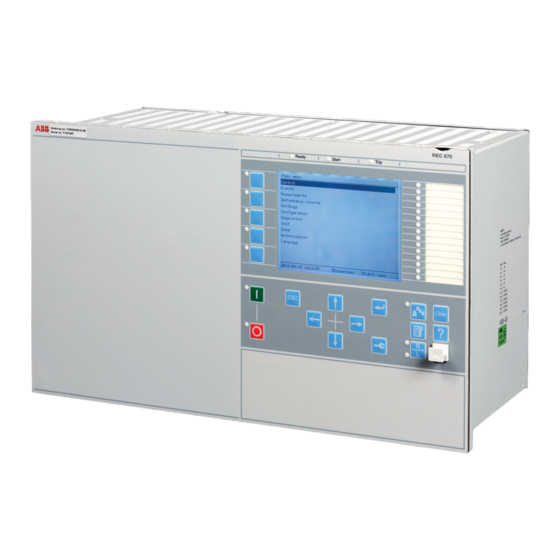
Bay control REC670 1MRK 511 404-BEN N Version 2.2 when IEC/UCA 61850-9-2LE process bus communication is used. 19. Human machine interface M11345-3 v12 Local HMI Precision time protocol PTP AMU0600442 v15 PTP according to IEEE 1588-2008 and specifically its profile IEC/IEEE 61850-9-3 for power utility automation is a synchronization method that can be used to maintain a common time within a station. -
Page 47: Station Communication
Bay control REC670 1MRK 511 404-BEN N Version 2.2 protocol (PRP) is available as an option when ordering IEC 61850-8-1 communication protocol IEDs. PRP according to IEC 62439-3 uses two optical/ M14787-3 v16 IEC 61850 Ed.1 or Ed.2 can be chosen by a setting in Galvanic(RJ45) Ethernet ports. - Page 48 SPA communication protocol SEMOD120134-5 v1 I103SUPERV is a function block with defined functions A single glass or plastic port is provided for the ABB SPA for supervision indications in monitor direction. This protocol. This allows extensions of simple substation FunctionType parameter; the...
-
Page 49: Remote Communication
Bay control REC670 1MRK 511 404-BEN N Version 2.2 Binary signal transfer Function commands generic for IEC 60870-5-103 SEMOD52522-4 v10 I103GENCMD The remote end data communication is used for the I103GENCMD is used for transmitting generic transmission of analog values for line differential commands over IEC 60870-5-103. -
Page 50: Hardware Description
Bay control REC670 1MRK 511 404-BEN N Version 2.2 Optical Ethernet module M16073-3 v9 The optical Ethernet module (OEM) provides two 24. Hardware description additional optical Ethernet ports. The port connectors are of optical (type LC) or galvanic (type RJ45) Ethernet Hardware modules ports. - Page 51 Bay control REC670 1MRK 511 404-BEN N Version 2.2 Transformer input module TRM M14875-3 v10 The transformer input module is used to galvanically separate and adapt the secondary currents and voltages generated by the measuring transformers. The module has twelve inputs in different combinations of currents and voltage inputs.
- Page 52 Bay control REC670 1MRK 511 404-BEN N Version 2.2 Table 12. Case dimensions, continued Case size (mm)/ (inches) The G and H dimensions are defined by the 19” rack mounting kit. Mounting alternatives M16079-3 v14 • 19” rack mounting kit •...
-
Page 53: Connection Diagrams
1446-18 IEC 61850 Ed2 level A1 10175313-INC 20-2185rev1 certificate issued by DNV GL IEC 61850 Ed1 level B1 1KHL050130 certificate issued by ABB Power Grids Switzerland Ltd, System Verification and Validation Center, SVC Baden IEC 60870-5-103 certificate 10021419-OPE/INC 16-2490 issued by DNV GL DNP 3.0 certificate issued by... -
Page 54: Technical Data
Bay control REC670 1MRK 511 404-BEN N Version 2.2 27. Technical data General M10993-1 v4 IP11376-1 v3 Definitions Reference value The specified value of an influencing factor to which are referred the characteristics of the equipment Nominal range The range of values of an influencing quantity (factor) within which, under specified conditions, the equipment meets the specified requirements Operative range The range of values of a given energizing quantity for which the equipment, under specified conditions, is able to... - Page 55 Bay control REC670 1MRK 511 404-BEN N Version 2.2 Energizing quantities, rated values and limits Analog inputs M16988-1 v11 IP15842-1 v1 Table 13. TRM - Energizing quantities, rated values and limits for protection transformer Description Value Frequency Rated frequency f 50/60 Hz Operating range ±...
- Page 56 Bay control REC670 1MRK 511 404-BEN N Version 2.2 Table 14. TRM - Energizing quantities, rated values and limits for measuring transformer Description Value Frequency Rated frequency f 50/60 Hz Operating range ± 10% Current inputs Rated current I Operating range (0-1.8) ×...
- Page 57 Bay control REC670 1MRK 511 404-BEN N Version 2.2 Binary inputs and outputs M12576-1 v13 IP15844-1 v1 Table 17. BIM - Binary input module Quantity Rated value Nominal range Binary inputs DC voltage, RL 24/30 V RL ±20% 48/60 V RL ±20% 110/125 V RL ±20%...
- Page 58 Bay control REC670 1MRK 511 404-BEN N Version 2.2 Table 19. IOM - Binary input/output module Quantity Rated value Nominal range Binary inputs DC voltage, RL 24/30 V RL ±20% 48/60 V RL ±20% 110/125 V RL ±20% 220/250 V RL ±20% Power consumption 24/30 V, 50 mA...
- Page 59 Bay control REC670 1MRK 511 404-BEN N Version 2.2 M12318-1 v11 Table 20. IOM - Binary input/output module contact data (reference standard: IEC 61810-1) Function or quantity Trip and signal relays Fast signal relays (parallel reed relay) Binary outputs Max system voltage 250 V AC/DC 250 V DC Min load voltage...
- Page 60 Bay control REC670 1MRK 511 404-BEN N Version 2.2 M12584-1 v11 Table 21. IOM with MOV and IOM 220/250 V, 110mA - contact data (reference standard: IEC 61810-1) Function or quantity Trip and Signal relays Fast signal relays (parallel reed relay) Binary outputs IOM: 10 IOM: 2...
- Page 61 Bay control REC670 1MRK 511 404-BEN N Version 2.2 SEMOD175395-2 v11 Table 22. SOM - Static Output Module data (reference standard: IEC 61810-1): Heavy duty static binary outputs Function of quantity Static binary output trip Max system voltage 250 V DC Number of outputs Impedance open state High impedance...
- Page 62 Bay control REC670 1MRK 511 404-BEN N Version 2.2 Table 23. SOM - Static Output module data (reference standard: IEC 61810-1): Electromechanical relay outputs Function of quantity Trip and signal relays Max system voltage 250 V AC/DC Min load voltage 24 V DC Number of outputs Test voltage across open contact, 1 min...
- Page 63 Bay control REC670 1MRK 511 404-BEN N Version 2.2 M12441-1 v11 Table 24. BOM - Binary output module contact data (reference standard: IEC 61810-1) Function or quantity Trip and Signal relays Binary outputs Max system voltage 250 V AC/DC Min load voltage 24V DC Test voltage across open contact, 1 min 1000 V rms...
- Page 64 Bay control REC670 1MRK 511 404-BEN N Version 2.2 Table 26. Auxiliary DC supply voltage influence on functionality during operation Dependence on Reference value Within nominal Influence range Ripple, in DC auxiliary voltage max. 2% 15% of EL 0.01%/% Operative range Full wave rectified Auxiliary voltage dependence,...
- Page 65 Bay control REC670 1MRK 511 404-BEN N Version 2.2 Type tests according to standards M16706-1 v15 IP15778-1 v1 Table 28. Electromagnetic compatibility Test Type test values Reference standards 1 MHz burst disturbance 2.5 kV IEC 60255-26 100 kHz slow damped oscillatory wave immunity test 2.5 kV IEC 61000-4-18, Level 3 Ring wave immunity test, 100 kHz...
- Page 66 Bay control REC670 1MRK 511 404-BEN N Version 2.2 Table 30. Environmental conditions Description Value Operating temperature range -25°C to +55°C (continuous) Short-time service temperature range -40°C to +70°C (<16h) Note: Degradation in MTBF and HMI performance outside the temperature range of -25°C to +55°C Relative humidity <93%, non-condensing Atmospheric pressure...
- Page 67 Bay control REC670 1MRK 511 404-BEN N Version 2.2 Differential protection M13081-1 v13 Table 34. High impedance differential protection, single phase HZPDIF Function Range or value Accuracy Operate voltage (10-900) V ±1.0% of I at I ≤ I I=U/R ±1.0% of I at I > I Reset ratio >95% at (30-900) V Maximum continuous power...
- Page 68 Bay control REC670 1MRK 511 404-BEN N Version 2.2 Impedance protection M16043-1 v14 Table 35. Automatic switch onto fault logic ZCVPSOF Parameter Range or value Accuracy UBase Operate voltage, detection of dead (1–100)% of ±0.5% of U line IBase Operate current, detection of dead (1–100)% of ±1.0% of I line...
- Page 69 Bay control REC670 1MRK 511 404-BEN N Version 2.2 Wide area measurement system GUID-F0BAEBD8-E361-4D50-9737-7DF8B043D66A v5 Table 36. Protocol reporting via IEEE 1344 and IEC/IEEE 60255-118 (C37.118) PMUREPORT Influencing quantity Range Accuracy Signal frequency ± 0.1 x f ≤ 1.0% TVE Signal magnitude: Voltage phasor (0.1–1.2) x U...
- Page 70 Bay control REC670 1MRK 511 404-BEN N Version 2.2 Current protection M12336-1 v14 Table 37. Instantaneous phase overcurrent protection PHPIOC Function Range or value Accuracy Operate current (5-2500)% of lBase ±1.0% of I at I ≤ I ±1.0% of I at I > I Reset ratio >...
- Page 71 Bay control REC670 1MRK 511 404-BEN N Version 2.2 M12342-1 v22 Table 38. Directional phase overcurrent protection, four steps OC4PTOC Function Range or value Accuracy lBase Operate current, step 1-4 (5-2500)% of ±1.0% of I at I ≤ I ±1.0% of I at I > I lBase Reset ratio >...
- Page 72 Bay control REC670 1MRK 511 404-BEN N Version 2.2 M12340-2 v9 Table 39. Instantaneous residual overcurrent protection EFPIOC Function Range or value Accuracy Operate current (5-2500)% of lBase ±1.0% of I at I ≤ I ±1.0% of I at I > I Reset ratio >...
- Page 73 Bay control REC670 1MRK 511 404-BEN N Version 2.2 M15223-1 v18 Table 40. Directional residual overcurrent protection, four steps EF4PTOC Function Range or value Accuracy Operate current, step 1-4 (1-2500)% of IBase ±1.0% of I at I ≤ I ±1.0% of I at I > I Reset ratio >...
- Page 74 Bay control REC670 1MRK 511 404-BEN N Version 2.2 GUID-E83AD807-8FE0-4244-A50E-86B9AF92469E v6 Table 41. Four step directional negative phase sequence overcurrent protection NS4PTOC Function Range or value Accuracy lBase Operate current, step 1 - 4 (1-2500)% of ±1.0% of I at I £ I ±1.0% of I at I >...
- Page 75 Bay control REC670 1MRK 511 404-BEN N Version 2.2 SEMOD173350-2 v16 Table 42. Sensitive directional residual overcurrent and power protection SDEPSDE Function Range or value Accuracy (0.25-200.00)% of IBase Operate level for 3I ·cosj directional ±1.0% of I at I £ I residual overcurrent ±1.0% of I at I >...
- Page 76 Bay control REC670 1MRK 511 404-BEN N Version 2.2 M12352-1 v15 Table 43. Thermal overload protection, one time constant LCPTTR/LFPTTR Function Range or value Accuracy Reference current (2-400)% of IBase ±1.0% of I Reference temperature (0-300)°C, (0 - 600)°F ±1.0°C, ±2.0°F Operate time: IEC 60255-149, ±5.0% or ±200 ms whichever is greater Time constant t = (1–1000)
- Page 77 Bay control REC670 1MRK 511 404-BEN N Version 2.2 M12353-1 v15 Table 45. Breaker failure protection CCRBRF Function Range or value Accuracy lBase Operate phase current (5-200)% of ±1.0% of I at I £ I ±1.0% of I at I > I Reset ratio, phase current >...
- Page 78 Bay control REC670 1MRK 511 404-BEN N Version 2.2 SEMOD175152-2 v11 Table 48. Directional underpower protection GUPPDUP Function Range or value Accuracy SBase Power level (0.0–500.0)% of ±1.0% of S at S ≤ S for Step 1 and Step 2 ±1.0% of S at S >...
- Page 79 Bay control REC670 1MRK 511 404-BEN N Version 2.2 GUID-6A7DA510-E145-4C5B-A7DC-97BC4258E621 v10 Table 51. Capacitor bank protection CBPGAPC Function Range or value Accuracy Operate value, overcurrent (10-900)% of lBase ±2.0% of I at I ≤ I ±2.0% of I at I > I Reset ratio, overcurrent >95% at (100-900)% of IBase Start time, overcurrent, at 0.5 x...
- Page 80 Bay control REC670 1MRK 511 404-BEN N Version 2.2 GUID-7EA9731A-8D56-4689-9072-D72D9CDFD795 v8 Table 52. Voltage-restrained time overcurrent protection VRPVOC Function Range or value Accuracy Start overcurrent (2.0 - 5000.0)% of IBase ±1.0% of I at I ≤ I ±1.0% of I at I > I Reset ratio, overcurrent >...
- Page 81 Bay control REC670 1MRK 511 404-BEN N Version 2.2 GUID-BCCA5F2D-9FF7-4188-9B5D-DA05E8E80CC0 v1 Table 53. Average Power Transient Earth Fault Protection APPTEF Function Range or value Accuracy Minimum operate level for residual (5-80)% of UBase ±0.5% of Ur overvoltage 3Uo> start condition "UN>" Reset ratio for residual overvoltage 3Uo>...
- Page 82 Bay control REC670 1MRK 511 404-BEN N Version 2.2 Voltage protection M13290-1 v15 Table 54. Two step undervoltage protection UV2PTUV Function Range or value Accuracy UBase Operate voltage, low and high step (1.0–100.0)% of ±0.5% of U UBase Absolute hysteresis (0.0–50.0)% of ±0.5% of U UBase...
- Page 83 Bay control REC670 1MRK 511 404-BEN N Version 2.2 M13304-1 v15 Table 55. Two step overvoltage protection OV2PTOV Function Range or value Accuracy UBase Operate voltage, step 1 and 2 (1.0-200.0)% of ±0.5% of U at U ≤ U ±0.5% of U at U > U UBase Absolute hysteresis (0.0–50.0)% of...
- Page 84 Bay control REC670 1MRK 511 404-BEN N Version 2.2 M13317-2 v15 Table 56. Residual overvoltage protection, two steps ROV2PTOV Function Range or value Accuracy UBase Operate voltage, step 1 - step 2 (1.0-200.0)% of ± 0.5% of U at U ≤ U ±...
- Page 85 Bay control REC670 1MRK 511 404-BEN N Version 2.2 SEMOD175210-2 v6 Table 58. Loss of voltage check LOVPTUV Function Range or value Accuracy Operate voltage (1–100)% of UBase ±0.5% of U Pulse timer when disconnecting all three (0.050–60.000) s ±0.2% or ±15 ms whichever is greater phases Time delay for enabling the functions after (0.000–60.000) s...
- Page 86 Bay control REC670 1MRK 511 404-BEN N Version 2.2 Unbalance protection GUID-ABB8C954-A47E-47E2-BD6B-1632325FE0C9 v1 Table 59. Shunt Capacitor Cascading Failure Protection SCCFPVOC Function Range Accuracy Measuring current input NegSeq, -3*ZeroSeq Measuring voltage input NegSeq, -3*ZeroSeq Operating characteristics Voltage restrained over-current ±1.0% of I at I ≤...
- Page 87 Bay control REC670 1MRK 511 404-BEN N Version 2.2 GUID-42E90A81-B44D-42C1-B9B5-CD4CDB6E376C v1 Table 61. Phase voltage differential based capacitor bank unbalanced protection SCPDPTOV Parameters Range Accuracy Phase voltage differential level (1.0-95.0) % of UBase ±0.5% of Ur Reset Ratio >90 % at (5.0 – 95.0)% of UBase >45% at (1.0 –...
- Page 88 Bay control REC670 1MRK 511 404-BEN N Version 2.2 Frequency protection M13360-1 v16 Table 63. Underfrequency protection SAPTUF Function Range or Value Accuracy Operate value, start function, at (35.00 - 75.00) Hz ±2.0 mHz symmetrical three phase voltage, StartFrequency Reset hysteresis 10.0 mHz fixed ±2.0 mHz Start time measurement...
- Page 89 Bay control REC670 1MRK 511 404-BEN N Version 2.2 M14964-1 v13 Table 64. Underfrequency protection SAPTOF Function Range or Value Accuracy Operate value, start function, (35.00 - 90.00) Hz ±2.0 mHz at symmetrical three phase voltage, StartFrequency 10.0 mHz fixed ±2.0 mHz Reset hysteresis Start time measurement with...
- Page 90 Bay control REC670 1MRK 511 404-BEN N Version 2.2 GUID-E8D0EE7C-D7B8-46C3-9C0D-363FFC75DE93 v5 Table 66. Frequency accumulation protection FTAQFVR Function Range or value Accuracy Operate value, frequency high limit level at (35.00 – 90.00) Hz ±2.0 mHz symmetrical three phase voltage Operatevalue, frequency low limit level at (30.00 –...
- Page 91 Bay control REC670 1MRK 511 404-BEN N Version 2.2 Multipurpose protection M13095-2 v11 Table 67. General current and voltage protection CVGAPC Function Range or value Accuracy Measuring current input phase1, phase2, phase3, PosSeq, - NegSeq, -3*ZeroSeq, MaxPh, MinPh, UnbalancePh, phase1- phase2, phase2-phase3, phase3- phase1, MaxPh-Ph, MinPh-Ph, UnbalancePh-Ph...
- Page 92 Bay control REC670 1MRK 511 404-BEN N Version 2.2 Table 67. General current and voltage protection CVGAPC, continued Function Range or value Accuracy Start undervoltage, step 1 - 2 (2.0 - 150.0)% of UBase ±0.5% of U at U ≤ U ±0.5% of U at U >...
- Page 93 Bay control REC670 1MRK 511 404-BEN N Version 2.2 Table 67. General current and voltage protection CVGAPC, continued Function Range or value Accuracy Impulse margin time 15 ms typically Undervoltage: Critical impulse time 10 ms typically at 1.2 x U to 0.8 x Impulse margin time 15 ms typically...
- Page 94 Bay control REC670 1MRK 511 404-BEN N Version 2.2 Secondary system supervision M12358-1 v10 Table 68. Current circuit supervision CCSSPVC Function Range or value Accuracy Operate current (10-200)% of IBase ±10.0% of I at I ≤ I ±10.0% of I at I > I Reset ratio, Operate current >90% Block current...
- Page 95 Bay control REC670 1MRK 511 404-BEN N Version 2.2 GUID-E2EA8017-BB4B-48B0-BEDA-E71FEE353774 v5 Table 70. Fuse failure supervision VDSPVC Function Range or value Accuracy Operate value, block of main fuse failure (10.0-80.0)% of UBase ±0.5% of Ur Reset ratio <110% Operate time, block of main fuse failure at 1 x U Min.
- Page 96 Bay control REC670 1MRK 511 404-BEN N Version 2.2 Control M12359-1 v15 Table 73. Synchronizing, synchrocheck and energizing check SESRSYN Function Range or value Accuracy Phase shift, j (-180 to 180) degrees line Voltage high limit for synchronizing and synchrocheck (50.0-120.0)% of UBase ±0.5% of U at U ≤...
- Page 97 Bay control REC670 1MRK 511 404-BEN N Version 2.2 M12379-1 v13 Table 74. Autorecloser SMBRREC Function Range or value Accuracy Dead time: shot 1 “t1 1Ph” (0.000-120.000) s ±0.2% or ±35 ms shot 1 “t1 2Ph” whichever is greater shot 1 “t1 3Ph “ shot 1 “t1 3PhHS”...
- Page 98 Bay control REC670 1MRK 511 404-BEN N Version 2.2 SEMOD175215-2 v14 Table 75. Voltage control TR1ATCC/TR8ATCC , TCMYLTC/TCLYLTC Function Range or value Accuracy Transformer reactance (0.1–200.0) Ω, primary Time delay for lower command when fast step down mode is (1.0–100.0) s activated Voltage control set voltage (85.0–120.0)% of UBase...
- Page 99 Bay control REC670 1MRK 511 404-BEN N Version 2.2 Table 75. Voltage control TR1ATCC/TR8ATCC , TCMYLTC/TCLYLTC , continued Function Range or value Accuracy Time after position change before the value is accepted (1–60) s ±0.2% or ±200 ms whichever is greater Tap changer constant time-out (1–120) s ±0.2% or ±200 ms...
- Page 100 Bay control REC670 1MRK 511 404-BEN N Version 2.2 Scheme communication M16038-1 v14 Table 76. Scheme communication logic with delta based blocking scheme signal transmit ZCPSCH Function Range or value Accuracy Scheme type Intertrip Permissive UR Permissive OR Blocking DeltaBlocking Operate voltage, Delta U (0–100)% of UBase ±5.0% of ΔU...
- Page 101 Bay control REC670 1MRK 511 404-BEN N Version 2.2 GUID-CC9A02C2-AAE8-4B8C-A091-D4ED584A2EA7 v1 Table 79. Local acceleration logic ZCLCPSCH Function Range or value Accuracy Operate current, LoadCurr (1–100)% of IBase ±1.0% of I Operate current, MinCurr (1–100)% of IBase ±1.0% of I Delay time on pick-up for current release (0.000–60.000) s ±0.2% or ±35 ms whichever is greater...
- Page 102 Bay control REC670 1MRK 511 404-BEN N Version 2.2 Logic M12380-1 v15 Table 81. Tripping logic common 3-phase output SMPPTRC Function Range or value Accuracy Program Trip action, 3 phase, 1ph/2ph, 1ph/2ph/3ph Minimum trip pulse (0.000-60.000) s ±0.2% or ±15 ms whichever is greater length , tTripMin tWaitForPHS...
- Page 103 Bay control REC670 1MRK 511 404-BEN N Version 2.2 GUID-EAA43288-01A5-49CF-BF5B-9ABF6DC27D85 v2 Table 87. Number of INDCALH instances Function Quantity with cycle time 3 ms 8 ms 100 ms INDCALH GUID-D1179280-1D99-4A66-91AC-B7343DBA9F23 v3 Table 88. Number of AND instances Logic block Quantity with cycle time 3 ms 8 ms 100 ms...
- Page 104 Bay control REC670 1MRK 511 404-BEN N Version 2.2 GUID-BE6FD540-E96E-4F15-B2A2-12FFAE6C51DB v2 Table 94. Number of RSMEMORY instances Logic block Quantity with cycle time 3 ms 8 ms 100 ms RSMEMORY GUID-7A0F4327-CA83-4FB0-AB28-7C5F17AE6354 v2 Table 95. Number of SRMEMORY instances Logic block Quantity with cycle time 3 ms 8 ms...
- Page 105 Bay control REC670 1MRK 511 404-BEN N Version 2.2 GUID-77FEBE9B-0882-4E85-8B1A-7671807BFC02 v2 Table 101. Number of INVALIDQT instances Logic block Quantity with cycle time 3 ms 8 ms 100 ms INVALIDQT GUID-F25B94C6-9CC9-48A0-A7A3-47627D2B56E2 v1 Table 102. Number of INVERTERQT instances Logic block Quantity with cycle time 3 ms 8 ms...
- Page 106 Bay control REC670 1MRK 511 404-BEN N Version 2.2 GUID-1C381E02-6B9E-44DC-828F-8B3EA7EDAA54 v1 Table 108. Number of XORQT instances Logic block Quantity with cycle time 3 ms 8 ms 100 ms XORQT GUID-19810098-1820-4765-8F0B-7D585FFC0C78 v8 Table 109. Number of instances in the extension logic package Logic block Quantity with cycle time 3 ms...
- Page 107 Bay control REC670 1MRK 511 404-BEN N Version 2.2 GUID-A339BBA3-8FD0-429D-BB49-809EAC4D53B0 v2 Table 113. Number of ITBGAPC instances Function Quantity with cycle time 3 ms 8 ms 100 ms ITBGAPC GUID-B258726E-1129-47C9-94F9-BE634A2085FA v4 Table 114. Elapsed time integrator with limit transgression and overflow supervision TEIGAPC Function Cycle time (ms) Range or value...
- Page 108 Bay control REC670 1MRK 511 404-BEN N Version 2.2 Monitoring M12386-1 v16 Table 118. Power system measurement CVMMXN Function Range or value Accuracy Frequency (0.95-1.05) x f ±2.0 mHz Voltage (10 to 300) V ±0.3% of U at U ≤ 50 V ±0.2% of U at U >...
- Page 109 Bay control REC670 1MRK 511 404-BEN N Version 2.2 GUID-ED634B6D-9918-464F-B6A4-51B78129B819 v6 Table 121. Voltage measurement phase-earth VNMMXU Function Range or value Accuracy Voltage (5 to 175) V ±0.5% of U at U ≤ 50 V ±0.2% of U at U > 50 V Phase angle (5 to 175) V ±0.5 degrees at U ≤...
- Page 110 Bay control REC670 1MRK 511 404-BEN N Version 2.2 M12760-1 v12 Table 125. Disturbance report DRPRDRE Function Range or value Accuracy Pre-fault time (0.05–9.90) s Post-fault time (0.1–10.0) s Limit time (0.5–10.0) s Maximum number of recordings 200, first in - first out Time tagging resolution 1 ms See table...
- Page 111 Bay control REC670 1MRK 511 404-BEN N Version 2.2 GUID-83B0F607-D898-403A-94FD-7FE8D45C73FF v9 Table 127. Insulation supervision for liquid medium function SSIML Function Range or value Accuracy Oil alarm level 1.00-100.00 ±10.0% of set value or 0.2 whichever is greater Oil lockout level 1.00-100.00 ±10.0% of set value or 0.2 whichever is greater Temperature alarm level...
- Page 112 Bay control REC670 1MRK 511 404-BEN N Version 2.2 GUID-F6B6ED6B-2488-483C-B068-3F4631F34DC8 v1 Table 130. Transformer loss of life LOLSPTR Function Range or value Accuracy Service value, hot spot temperature – ±2.0% of expected value Service value, top oil temperature – ±2.0% of expected value Service value, loss of life –...
- Page 113 Bay control REC670 1MRK 511 404-BEN N Version 2.2 M12384-1 v8 Table 135. Disturbance recorder Function Value Buffer capacity Maximum number of analog inputs Maximum number of binary inputs Maximum number of disturbance reports Maximum total recording time (3.4 s recording time and maximum 340 seconds (100 recordings) at 50 Hz number of channels, typical value) 280 seconds (80 recordings) at 60 Hz...
- Page 114 Bay control REC670 1MRK 511 404-BEN N Version 2.2 GUID-C43B8654-60FE-4E20-8328-754C238F4AD0 v3 Relion® 670 series can store up to 10240 security events. Table 136. Event counter with limit supervision L4UFCNT Function Range or value Accuracy Counter value 0-65535 Hitachi Power Grids ©...
- Page 115 Bay control REC670 1MRK 511 404-BEN N Version 2.2 Table 136. Event counter with limit supervision L4UFCNT , continued Function Range or value Accuracy Max. count up speed 30 pulses/s (50% duty cycle) GUID-F5E124E3-0B85-41AC-9830-A2362FD289F2 v1 Table 137. Running hour-meter TEILGAPC Function Range or value Accuracy...
- Page 116 Bay control REC670 1MRK 511 404-BEN N Version 2.2 GUID-2068BBA0-9026-48D0-9DEB-301BCB3C600C v2 Table 140. Voltage harmonic monitoring VHMMHAI (50/60 Hz) Function Range or value Accuracy Fundamental Harmonic Frequency (0.95 - 1.05) X f 2nd order to 5th order (0.1 - 0.5) X U ±...
- Page 117 Bay control REC670 1MRK 511 404-BEN N Version 2.2 Metering M13404-2 v5 Table 141. Pulse-counter logic PCFCNT Function Setting range Accuracy Input frequency See Binary Input Module (BIM) Cycle time for report of (1–3600) s counter value SEMOD153707-2 v5 Table 142. Function for energy calculation and demand handling ETPMMTR Function Range or value Accuracy...
- Page 118 Bay control REC670 1MRK 511 404-BEN N Version 2.2 Station communication M15031-1 v9 Table 143. Communication protocols Function Value Protocol IEC 61850-8-1 Communication speed for the IEDs 100BASE-FX Protocol IEC 60870–5–103 Communication speed for the IEDs 9600 or 19200 Bd Protocol DNP3.0 Communication speed for the IEDs...
- Page 119 Bay control REC670 1MRK 511 404-BEN N Version 2.2 M12589-1 v5 Table 148. SLM – LON port Quantity Range or value Optical connector Glass fiber: type ST Plastic fiber: type HFBR snap-in Fiber, optical budget Glass fiber: 11 dB (1000m/3000 ft typically *) Plastic fiber: 7 dB (10m/35 ft typically *) Fiber diameter Glass fiber: 62.5/125 mm...
- Page 120 Bay control REC670 1MRK 511 404-BEN N Version 2.2 Table 152. SFP - Galvanic RJ45 Quantity Rated value Number of channels Up to 6 single or 3 redundant or a combination of single and redundant links for communication using any protocol Standard IEEE 802.3u 100BASE-TX Type of cable...
- Page 121 Bay control REC670 1MRK 511 404-BEN N Version 2.2 Remote communication M12756-1 v13 Table 154. Line data communication module Characteristic Range or value Type of LDCM Short range (SR) Medium range (MR) Long range (LR) Type of fiber Multi-mode fiber Single-mode fiber Single-mode fiber glass 62.5/125 µm...
- Page 122 Bay control REC670 1MRK 511 404-BEN N Version 2.2 Hardware M11778-1 v7 SEMOD53385-1 v1 Table 156. Case Material Steel sheet Front plate Stainless steel with cut-out for HMI Surface treatment Aluzink preplated steel Finish Light grey (RAL 7035) M12327-1 v5 Table 157.
- Page 123 Bay control REC670 1MRK 511 404-BEN N Version 2.2 GUID-96676D5D-0835-44DA-BC22-058FD18BDF34 v3 Because of limitations of space, when ring lug terminal is ordered for Binary I/O connections, one blank slot is necessary between two adjacent I/O modules. Please refer to the ordering particulars for details.
- Page 124 Bay control REC670 1MRK 511 404-BEN N Version 2.2 Basic IED functions M11963-1 v5 Table 164. Self supervision with internal event list Data Value Recording manner Continuous, event controlled List size 40 events, first in-first out M12331-1 v9 Table 165. Time synchronization, time tagging Function Value Time tagging accuracy of the synchrophasor data...
- Page 125 Bay control REC670 1MRK 511 404-BEN N Version 2.2 SEMOD141136-2 v10 Table 169. IRIG-B Quantity Rated value Number of channels IRIG-B Number of optical channels Electrical connector: Electrical connector IRIG-B Pulse-width modulated 5 Vpp Amplitude modulated – low level 1-3 Vpp –...
- Page 126 Bay control REC670 1MRK 511 404-BEN N Version 2.2 Inverse characteristic M12388-1 v23 Table 170. ANSI Inverse time characteristics Function Range or value Accuracy Operating characteristic: 0.05 ≤ k ≤ 999.00 ANSI/IEEE C37.112 , 1.5 x I ≤ I ≤ 20 x I ±2.0% or ±40 ms whichever is greater æ...
- Page 127 Bay control REC670 1MRK 511 404-BEN N Version 2.2 Table 171. IEC Inverse time characteristics Function Range or value Accuracy Operating characteristic: 0.05 ≤ k ≤ 999.00 IEC 60255-151, ±2.0% 1.5 x I ≤ I ≤ 20 x I or ±40 ms whichever is greater æ...
- Page 128 Bay control REC670 1MRK 511 404-BEN N Version 2.2 Table 172. RI and RD type inverse time characteristics Function Range or value Accuracy RI type inverse characteristic 0.05 ≤ k ≤ 999.00 IEC 60255-151, ±2.0% 1.5 x I ≤ I ≤ 20 x I or ±40 ms whichever is greater ×...
- Page 129 Bay control REC670 1MRK 511 404-BEN N Version 2.2 Table 174. IEC Inverse time characteristics for Sensitive directional residual overcurrent and power protection Function Range or value Accuracy Operating characteristic: 0.05 ≤ k ≤ 2.00 IEC 60255-151, ±5.0% 1.5 x I ≤...
- Page 130 Bay control REC670 1MRK 511 404-BEN N Version 2.2 GUID-2AE8C92E-5DA8-487F-927D-8E553EE29240 v2 Table 176. ANSI Inverse time characteristics for Voltage restrained time overcurrent protection Function Range or value Accuracy Operating characteristic: 0.05 ≤ k ≤ 999.00 ANSI/IEEE C37.112 , ± 5.0% or ±40 ms whichever is greater æ...
- Page 131 Bay control REC670 1MRK 511 404-BEN N Version 2.2 SEMOD116978-2 v10 Table 178. Inverse time characteristics for overvoltage protection Function Range or value Accuracy Type A curve: k = (0.05-1.10) in steps of 0.01 ±5.0% or ±45 ms whichever is greater æ...
- Page 132 Bay control REC670 1MRK 511 404-BEN N Version 2.2 Table 179. Inverse time characteristics for undervoltage protection Function Range or value Accuracy Type A curve: k = (0.05-1.10) in steps of 0.01 ±5.0% or ±45 ms whichever is greater æ ö...
- Page 133 Bay control REC670 1MRK 511 404-BEN N Version 2.2 Table 180. Inverse time characteristics for residual overvoltage protection Function Range or value Accuracy Type A curve: k = (0.05-1.10) in steps ±5.0% or ±45 ms whichever is greater of 0.01 æ...
-
Page 134: Ordering For Customized Ied
Bay control REC670 1MRK 511 404-BEN N Version 2.2 28. Ordering for customized IED GUID-43BAC6E7-5454-464E-A4B0-97D2A602785D v12 Table 181. General guidelines Guidelines Carefully read and follow the set of rules to ensure problem-free order management. Please refer to the available functions table for included application functions. PCM600 can be used to make changes and/or additions to the delivered factory configuration of the pre-configured. - Page 135 Bay control REC670 1MRK 511 404-BEN N Version 2.2 Table 185. Differential protection Position Table 186. Differential functions Function Function Ordering no Position Available Selected Notes and rules identification High impedance differential protection, single phase HZPDIF 1MRK005904-HB 00–12 Table 187. Impedance protection Position Table 188.
- Page 136 Bay control REC670 1MRK 511 404-BEN N Version 2.2 Table 192. Voltage functions Function Function Ordering no Position Available Selected Notes and rules identification Two step undervoltage protection UV2PTUV 1MRK005912-AA Two step overvoltage protection OV2PTOV 1MRK005912-BA Residual overvoltage protection, two steps ROV2PTOV 1MRK005912-CE Voltage differential protection...
- Page 137 Bay control REC670 1MRK 511 404-BEN N Version 2.2 Table 202. Secondary system supervision functions Function Function Ordering no Position Available Selected Notes and rules identification Current circuit supervision CCSSPVC 1MRK005916-AC Fuse failure supervision FUFSPVC 1MRK005916-BA Fuse failure supervision based on voltage difference VDSPVC 1MRK005916-CA Table 203.
- Page 138 Additional local HMI user dialogue language No additional HMI language HMI language, English US 1MRK002920-UB Selected Additional 2nd languages are continuously being added. Please get in touch with local ABB sales contact. Table 214. Casing selection Casing Ordering no Selection Notes and rules 1/2 x 19"...
- Page 139 Bay control REC670 1MRK 511 404-BEN N Version 2.2 Table 215. Mounting selection Mounting details with IP40 of protection from the front Ordering no Selection Notes and rules No mounting kit included 19" rack mounting kit for 1/2 x 19" case or 2xRHGS6 or RHGS12 1MRK002420-BB 19"...
- Page 140 Bay control REC670 1MRK 511 404-BEN N Version 2.2 Table 218. Analog system selection Analog system Ordering no Selection Notes and rules When more than one TRM is selected, the connector type on both TRMs must be the same (A compression or B ring lug). Slot position (front view/rear view) No Transformer input module included TRM 12I 1A, 50/60Hz, compression terminals...
- Page 141 Bay control REC670 1MRK 511 404-BEN N Version 2.2 Table 219. Maximum quantity of I/O modules, with compression terminals When ordering I/O modules, observe the maximum quantities according to the tables below. Note: Standard order of location for I/O modules is BIM-BOM-SOM-IOM-MIM from left to right as seen from the rear side of the IED, but can also be freely placed.
- Page 142 Bay control REC670 1MRK 511 404-BEN N Version 2.2 Table 221. Binary input/output module selection Binary input/ Ordering no Selection Notes and rules output modules Slot position (front view/rear view) 1/2 case with 1 █ █ █ 3/4 case with 1 █...
- Page 143 Bay control REC670 1MRK 511 404-BEN N Version 2.2 Table 221. Binary input/output module selection, continued Binary input/ Ordering no Selection Notes and rules output modules IOM 8 inputs, RL 1MRK000173-BE 110-125 VDC, 50mA, 10+2 output relays IOM 8 inputs, RL 1MRK000173-CE 220-250 VDC, 50mA, 10+2...
- Page 144 Bay control REC670 1MRK 511 404-BEN N Version 2.2 Table 222. Station communication, remote end serial communication and time synchronization selection Station communication, remote end Ordering no Selection Notes and rules serial communication and time synchronization Slot position (front view/rear view) Available slots in 1/2, 3/4 and 1/1 █...
-
Page 145: Ordering For Pre-Configured Ied
Bay control, Double breaker 1MRK004814-BG Bay control, 1 1/2 breaker diameter 1MRK004814-CG Bay control, Single breaker, with PMU 1MRK004814-EG ACT configuration ABB standard configuration Selection for position #2 Hitachi Power Grids © Copyright 2017 Hitachi Power Grids. All rights reserved... - Page 146 No additional HMI language HMI language, English US 1MRK002920-UB Selection for position #4 Additional 2nd languages are continuously being added. Please get in touch with local ABB sales contact. Hitachi Power Grids © Copyright 2017 Hitachi Power Grids. All rights reserved...
- Page 147 Bay control REC670 1MRK 511 404-BEN N Version 2.2 Casing Ordering no Notes and rules 1/2 x 19" rack casing, 1 TRM 1MRK000151-VA 3/4 x 19" rack casing, 1 TRM 1MRK000151-VB 3/4 x 19" rack casing, 2 TRM 1MRK000151-VE 1/1 x 19" rack casing, 1 TRM 1MRK000151-VC 1/1 x 19"...
- Page 148 Bay control REC670 1MRK 511 404-BEN N Version 2.2 Analog system Ordering no Notes and rules When more than one TRM is selected, the connector type on both TRMs must be the same (A compression or B ring lug). Slot position (front view/rear view) No Transformer input module included TRM 9I 1A + 3U 110/220V, 50/60Hz, compression terminals 1MRK002247-BG...
- Page 149 Bay control REC670 1MRK 511 404-BEN N Version 2.2 Binary input/ Ordering no Notes and rules output module and mA input module For pulse counting, for example kWh metering, the BIM with enhanced pulse counting capabilities must be used. Note: 1 BIM required in position P3 and 1 BOM required in position P4. Products B30 and C30 require an extra BIM in position P5. Slot position (front view/rear view)
- Page 150 Bay control REC670 1MRK 511 404-BEN N Version 2.2 Binary input/ Ordering no Notes and rules output module and mA input module For pulse counting, for example kWh metering, the BIM with enhanced pulse counting capabilities must be used. Note: 1 BIM required in position P3 and 1 BOM required in position P4. Products B30 and C30 require an extra BIM in position P5. IOM 8 inputs, RL 1MRK000173-CF 220-250 VDC,...
- Page 151 Bay control REC670 1MRK 511 404-BEN N Version 2.2 Station communication, remote end Ordering no Notes and rules serial communication and time synchronization Slot position (front view/rear view) Available slots in 1/2 and 3/4 case █ █ █ █ █ █...
-
Page 152: Ordering For Accessories
(ordering number RK926 315- IEDs is described in 1MRK 512 001-BEN and 1MRK BE). 001024-CA. Please refer to the website: Multi-breaker/Single or Three Phase trip with external www.abb.com/protection-control for detailed neutral on current circuit (ordering number RK926 315- information. BV). - Page 153 Bay control REC670 1MRK 511 404-BEN N Version 2.2 Protection cover M15040-3 v8 Protective cover for rear side of RHGS6, 6U, 1/4 x 19” Quantity: 1MRK 002 420-AE Protective cover for rear side of terminal, 6U, 1/2 x 19” Quantity: 1MRK 002 420-AC Protective cover for rear side of terminal, 6U, 3/4 x 19”...
- Page 154 Bay control REC670 1MRK 511 404-BEN N Version 2.2 Specify additional quantity of IED Connect USB flash drive requested . Quantity: 1MRK 002 290-AE Hitachi Power Grids © Copyright 2017 Hitachi Power Grids. All rights reserved...
- Page 155 Bay control REC670 1MRK 511 404-BEN N Version 2.2 User documentation Specify the number of printed manuals requested Application manual Quantity: 1MRK 511 401-UEN ANSI Quantity: 1MRK 511 401-UUS Technical manual Quantity: 1MRK 511 402-UEN ANSI Quantity: 1MRK 511 402-UUS Commissioning manual Quantity: 1MRK 511 403-UEN...
- Page 156 Bay control REC670 1MRK 511 404-BEN N Version 2.2 ANSI Quantity: 1MRK 511 398-UUS Cyber security deployment guideline Quantity: 1MRK 511 399-UEN Application guide, Communication set-up Quantity: 1MRK 505 382-UEN Reference information M2175-3 v4 For our reference and statistics we would be pleased to be provided with the following application data: Country: End user: Station name:...
- Page 158 ABB Power Grids Sweden AB Grid Automation Products SE-721 59 Västerås, Sweden Phone +46 (0) 10 738 00 00 Scan this QR code to visit our website https://www.abb.com/protection-control © Copyright 2017 Hitachi Power Grids. All rights reserved.