Table of Contents
Quick Links
Table of Contents
Troubleshooting

Related Manuals for Canon imageRUNNER ADVANCE C5500 Series


Summary of Contents for Canon imageRUNNER ADVANCE C5500 Series
- Page 1 Revision 2.0 imageRUNNER ADVANCE C5500 Series Service Manual...
- Page 2 When changes occur in applicable products or in the contents of this manual, Canon will release technical information as the need arises. In the event of major changes in the contents of this manual over a long or short period, Canon will issue a new edition of this manual.
- Page 3 Introduction Symbols Explanation Symbols Explanation Disconnect the connector. Connect the power cable. Connect the connector. Disconnect the power cable. Remove the cable/wire from the Turn on the power. cable guide or wire saddle. Install the cable/wire to the cable Turn off the power. guide or wire saddle.
-
Page 4: Table Of Contents
Contents Contents Safety Precautions....................1 Laser Safety............................2 Handling of Laser System........................2 Turn power switch ON.........................2 Power Supply............................3 Toner Safety............................3 About Toner............................3 Handling Adhered Toner........................3 Notes When Handling a Lithium Battery..................... 3 Notes Before it Works Serving......................4 Points to Note at Cleaning........................4 Notes on Assembly/Disassembly...................... - Page 5 Contents Scanner Unit............................51 Pickup Feed System........................... 52 Fan..............................59 Power Supply Assembly........................60 Controller System..........................61 Specifications / Configuration.......................61 Motion Sensor.............................64 Shutdown Sequence........................... 65 Startup Sequence..........................66 Laser Exposure System........................67 Overview............................67 Laser ON/OFF Control.........................69 Horizontal Scanning Synchronization Control..................69 Vertical Scanning Synchronization Control....................70 APC (Auto Power Control)........................
- Page 6 Contents Environment Heater Control.......................154 Power Supply............................155 Power-saving Function........................156 Quick Startup............................ 159 3. Periodical Service..................161 Consumable Parts List........................162 Host machine............................162 Cassette Feeding Unit-AM1 ......................165 High Capacity Cassette Feeding Unit-A1.................... 166 Paper Deck Unit-F1........................... 166 Booklet Finisher-Y1........................... 167 Staple Finisher-Y1..........................167 Inner Finisher-H1..........................
- Page 7 Contents Removing the Secondary Transfer High Voltage Unit................266 Removing the AC Driver PCB......................268 Removing the Control Panel.......................269 Removing the All-night Power Supply PCB..................274 Removing the Developing High-Voltage PCB (YMC)/Charging High-Voltage PCB (YMC).......275 Laser Control System........................278 Cleaning the Dustproof Glass......................278 Removing the Dustproof Glass Cleaning Pad..................279 Removing the Laser Scanner Unit......................
- Page 8 Contents Cleaning the Pre-registration Guide Unit..................... 374 Cleaning the Registration Sensor....................... 375 Cleaning the Between-Cassette 1/2 Sensor..................376 Cleaning the Fixing Delivery Guide.....................378 Cleaning the Fixing Rear Roller......................379 Cleaning the Fixing Delivery Roller..................... 380 Removing the Duplex Feed Upper Rollers...................381 Removing the Duplex Feed Lower Roller....................
- Page 9 Contents How to use the test print........................443 Troubleshooting Items........................447 Fixing Wrinkle/Jams Caused by Deterioration in the Rib of the Fixing Inlet Guide........447 Display of "Non-Canon Product" Message..................448 Forcible stop of paper feed.........................449 Controller Self Diagnosis.........................452 Preface.............................452 Overview............................452 Basic Flowchart..........................454...
- Page 10 Contents Points to Note when Executing Service Mode..................659 Service Mode Menu...........................659 Description of Service Mode Items..................... 659 Operation Check of Electrical Components..................660 Enhanced I/O Information........................663 Security Support..........................665 Switching the Screen Display (Level 1 <->2)..................666 Service Mode Backup........................666 Output of Service Print Data.......................667 SITUATION Mode..........................
- Page 11 Contents Installing Stamp Cartridge ....................... 1124 Installing the Cleaning Tool......................1125 Securing the Host Machine......................1126 Turning the Main Power ON / Setting the Toner Container..............1126 Host Machine Settings (Starting the Setup Guide)................1127 Other Installations........................... 1129 Installing the Envelope Attachment....................1130 Checking after the Installation......................
- Page 12 Contents Installation Outline Drawing ......................1178 Preparation before Installation ..................... 1178 Installation Procedure ........................1179 Settings after installation ......................1180 Utility Tray-B1..........................1181 Points to Note when Installing......................1181 Checking the Contents........................1181 Installation Outline Drawing......................1181 Installation Procedure........................1181 When Installing the USB Keyboard....................1184 Copy Card Reader-F1/Copy Card Reader Attachment-B5............
- Page 13 Contents Checking the Contents........................1221 Check Item When Turning OFF the Main Power................1221 Installation Procedure........................1221 [TYPE-2] Removable HDD Kit.......................1224 Checking the Contents........................1224 Check Item When Turning OFF the Main Power................1224 Installation Procedure........................1224 [TYPE-3] Option HDD (1TB) + Removable HDD Kit..............1230 Checking the Contents........................1230 Check Item When Turning OFF the Main Power................
- Page 14 Contents Work Procedure..........................1300 Target PCBs of Automatic Update....................1303 List of Service Modes That Can Be Restored................1304...
-
Page 15: Safety Precautions
Safety Precautions Laser Safety.......... 2 Handling of Laser System..... 2 Turn power switch ON......2 Power Supply........3 Toner Safety..........3 Notes When Handling a Lithium Battery..........3 Notes Before it Works Serving....4 Points to Note at Cleaning....4 Notes on Assembly/Disassembly..4... -
Page 16: Laser Safety
Safety Precautions Laser Safety Since radiation emitted inside the machine is completely confined within protective housings, external covers and interlock switches, the laser beam cannot escape from the machine during any phase of user operation. Therefore this machine is classified in Class 1 laser products that are regarded as safe during normal use according to International Standard IEC60825-1. -
Page 17: Power Supply
Safety Precautions The machine goes on when the main power switch is turned on (i.e., other than in low power mode, sleep mode). CAUTION: Do not turn off the main power switch while the progress bar is indicated, during which access is made to the HDD. If deprived of power, the HDD can suffer a fault (E602). -
Page 18: Notes Before It Works Serving
Safety Precautions Notes Before it Works Serving • At servicing, be sure to turn OFF the power source according to the specified steps and disconnect the power plug. • Leaving the power plug connected for a long time in an environment having a lot of dust, moisture, or oily smoke will cause a fire. -
Page 19: Product Overview
Product Overview Product Lineup........6 Features..........11 Specifications........15 Parts Name......... 26... -
Page 20: Product Lineup
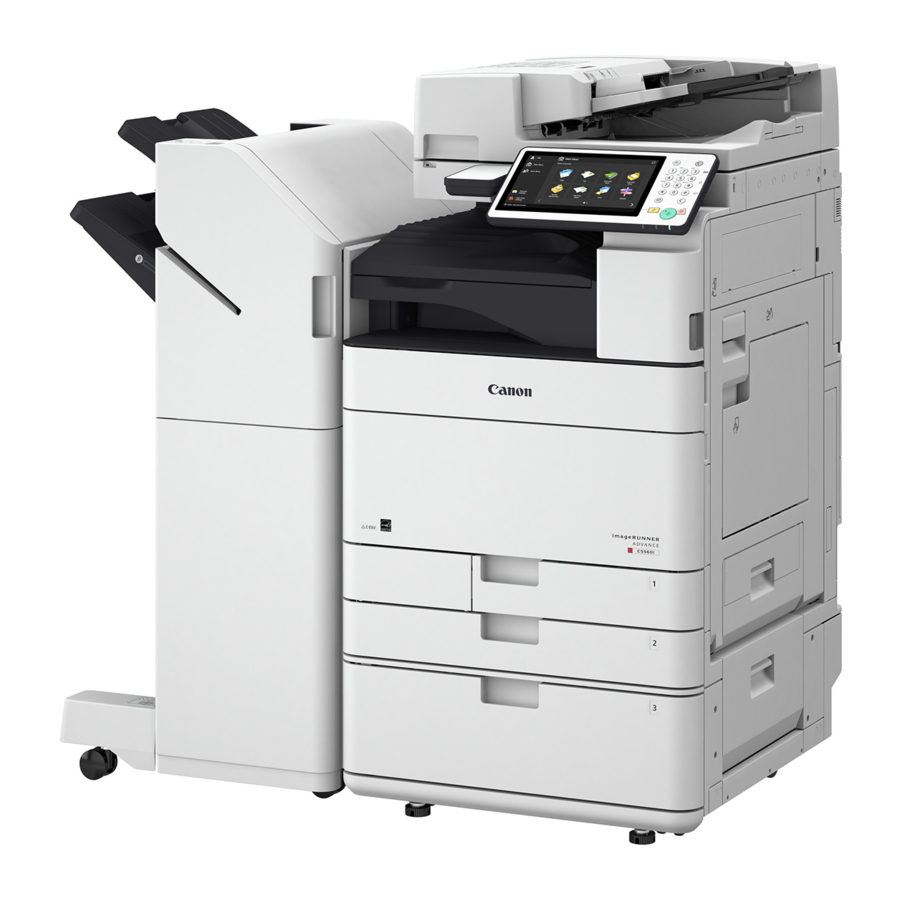
1. Product Overview Product Lineup Host machine imageRUNNER ADVANCE C5560 / C5550 / C5540 / C5535 The underlined numerical value indicates the print speed (ppm: print per minute). C5560 C5550 C5540 C5535 Print speed 60/60 ppm 50/50 ppm 40/40 ppm 35/35 ppm (BW/Color) Positioning... -
Page 21: Options
1. Product Overview Options ■ Pickup/Delivery System Options [10] [11] Product name Condition Copy Tray-J2 Paper Deck Unit-F1 Paper Deck Heater Unit-C1 2-cassette Pedestal-AM1 High Capacity Cassette Feeding Unit-A1 Cassette Heater Unit-41 FL Cassette-AZ1 FL Cassette-BA1 Tab Paper Attachment-F1 Inner 2-way Tray-J1 Buffer Path Unit-L1 Inner Finisher-H1 Inner 2/3 Hole Puncher-B1... - Page 22 1. Product Overview Product name Condition Inner 4 Hole Puncher-B1 [10] Saddle Finisher-Y1 [11] Staple Finisher-Y1 2/3 Hole Puncher Unit-A1 2/4 Hole Puncher Unit-A1 4 Hole Puncher Unit-A1 Power Supply Cable-U1 Power Supply Cable-W1 ■ Image Reading System Options Product name Condition Copyboard Cover Type W Cannot be installed with the DADF.
- Page 23 1. Product Overview ■ Function expansion system options [20] [19] [9],[10] [11],[12] Licence option [15],[16] [13],[14] [17],[18] Hardware Products Product name Condition NFC Kit-B1 (Flat Control Panel) IC Card Reader Box-C1 Connection Kit-A1 for Bluetooth LE Utility Tray-B1 Cannot be installed with Voice Guidance Kit-G1. Cannot be installed with Voice Operation Kit-D1.
- Page 24 1. Product Overview Product name Condition [14] Super G3 FAX Board-AS2 [15] Super G3 2nd Line Fax Board-AS1 Super G3 FAX Board-AS1 is required. [16] Super G3 2nd Line Fax Board-AS2 Super G3 FAX Board-AS2 is required. [17] Super G3 3rd/4th Line Fax Board-AS1 Super G3 FAX Board-AS1 is required.
-
Page 25: Features
1. Product Overview Features Product Features Improved business productivity Low initial cost /usability Reader/ADF Option - Adoption of double feed detection - Support of staple-free stapling / Support of high speed scanning - Support of manual stapling Improved operability Toner Container - Prevention of toner soiling by new toner supply mechanism High image quality... -
Page 26: Setup Guide
1. Product Overview Setup Guide Setup Guide is designed to improve the workability during the installation by enabling to implement the series of necessary setting items at installation of a device in the format of a navigation. The items that can be set are as follows: Display Setting screen Remarks... -
Page 27: Limiting Of Color Printing
1. Product Overview < Category > [SITUATION MODE] Detail Installation Items related to installation Troubleshooting Items related to troubleshooting Parts Replacement Items performed at parts replacement Major Adjustment Major items of adjustment Sensor Check Operation Check of Electrical Components Parts Check Limiting of Color Printing Even if an error attributed to the Developing Unit or drum of any of the Y/M/C colors has occurred, B&W printing and copying remain possible without entering the limited printer function mode where the entire printing function stops. - Page 28 1. Product Overview...
-
Page 29: Specifications
1. Product Overview Specifications Product Specifications Item Specification/Function Machine installation method Desktop type Light source Photosensitive medium OPC (30 mm dia.) Image reading sensor CMOS Exposure method Laser exposure Charging method Roller charging Developing method Dry, 2-component development Transfer method Intermediate Belt transfer (Primary transfer: Roller transfer, Secondary transfer: Roller transfer) Separation method Curvature separation + Static Eliminator... - Page 30 1. Product Overview Item Specification/Function Paper type Cassette: Thin paper (52 to 63 g/m ), Plain paper (64 to 105 g/m ), Recycled paper (64 to 105 g/m ), Heavy paper (106 to 256 g/m ), Colored paper, Pre-punched paper, Transparency, Clear film, Bond paper, Tab paper*2, Letterhead, Envelope Multi-purpose Tray: Thin paper (52 to 63 g/m...
-
Page 31: Weight And Size
1. Product Overview Weight and Size Product name Width (mm) Depth (mm) Height (mm) Weight: Approx. (kg) imageRUNNER ADVANCE C5560/C5550/ C5540/C5535 Platen Cover Model : Platen Cover Model : Platen Cover Model : 2-cassette Pedestal-AM1 22.5 High Capacity Cassette Feeding Unit-A1 Paper Deck Unit-F1 Inner Finisher-H1 Staple Finisher-Y1... - Page 32 1. Product Overview Size Feeding direction (mm) Width direction (mm) Custom paper size 4-5 216 to 269.9 195 to 209.9 Custom paper size 4-6 270 to 431.8 195 to 209.9 Custom paper size 4-7 216 to 269.9 210 to 256.9 Custom paper size 4-8 270 to 431.8 210 to 256.9...
- Page 33 1. Product Overview Paper size Pickup position Multi-pur- Cassette 1 Cassette 2 Cassette 3 Cassette 4 Paper Deck High Capaci- pose Tray Unit-F1 ty Cassette Feeding Unit- A-LTRR GLTR-R GLTR GLGL AFLS 16KR I-LGL Free Free (Long length) Custom size A* Custom size B* Custom size C* Custom size D*...
- Page 34 1. Product Overview Paper size Pickup position Multi-pur- Cassette 1 Cassette 2 Cassette 3 Cassette 4 Paper Deck High Capaci- pose Tray Unit-F1 ty Cassette Feeding Unit- LTRR STMTR STMT SRA3 12x18 EXEC OFFICIO E-OFFICIO B-OFFICIO M-OFFICIO A-OFFICIO A-LTR A-LTRR GLTR-R GLTR GLGL...
- Page 35 1. Product Overview Paper size Pickup position Multi-pur- Cassette 1 Cassette 2 Cassette 3 Cassette 4 Paper Deck High Capaci- pose Tray Unit-F1 ty Cassette Feeding Unit- 11x17 LTRR STMTR STMT SRA3 12x18 EXEC OFFICIO E-OFFICIO B-OFFICIO M-OFFICIO A-OFFICIO A-LTR A-LTRR GLTR-R GLTR...
- Page 36 1. Product Overview ■ Pickup Specifications (4/11) Type (paper weight: g/m2) • 1-Sided Coated 1 (106 to 163), 1-Sided Coated 2 (164 to 220), 1-Sided Coated 3 (221 to 256) • 2-Sided Coated 1 (106 to 163), 2-Sided Coated 2 (164 to 220), 2-Sided Coated 3 (221 to 256) •...
- Page 37 1. Product Overview • Custom paper size B: Custom paper size 1-4, Custom paper size 1-5, Custom paper size 1-6, Custom paper size 1-7, Custom paper size 2-1, Custom paper size 2-2, Custom paper size 2-3, Custom paper size 2-4, Custom paper size 2-5, Custom paper size 2-6, Custom paper size 2-7, Custom paper size 2-8, Custom paper size 3-1, Custom paper size 3-2, Custom paper size 3-3, Custom paper size 3-4, Custom paper size 4-1, Custom paper size 4-2, Custom paper size 4-3, Custom paper size 4-4, Custom paper size 4-5, Custom paper size 4-6, Custom paper size 4-7, Custom paper size 4-8, Custom...
- Page 38 1. Product Overview Paper size Pickup position Multi-pur- Cassette 1 Cassette 2 Cassette 3 Cassette 4 Paper Deck High Capaci- pose Tray Unit-F1 ty Cassette Feeding Unit- ■ Pickup Specifications (8/11) Type (paper weight: g/m2) • Bond paper (82 to 99) Paper size Pickup position Multi-pur-...
- Page 39 1. Product Overview Paper size Pickup position Multi-pur- Cassette 1 Cassette 2 Cassette 3 Cassette 4 Paper Deck High Capaci- pose Tray Unit-F1 ty Cassette Feeding Unit- COM10_R Monarch_R ISO-C5_R DL_R Nagagata 3_R Yougatanaga Kakugata 2_R COM10 Monarch ISO-C5 Nagagata 3 Yougatanaga 3 Free Free (Long...
-
Page 40: Parts Name
1. Product Overview Parts Name External View ■ Front side of the machine Name Name Motion Sensor Right Lower Cover Control Panel Right Lower Door Cassette Right Door USB Port (Right Front) Cassette 1 Right Upper Cover Cassette 2 USB Port (Right Rear) Waste Toner Cover USB Connector Toner Identification Mark... - Page 41 1. Product Overview Name Name Glass Cleaning Sheet Storage Box Toner Replacement Cover Delivery Tray Push-out Stopper Front Cover ■ Rear side of the machine Name Name Extension phone line terminal (LINE 4/LINE 3/LINE 2 Handset connection terminal (Handset) from above) Phone line terminal (LINE 1) External phone terminal (EXT.)
- Page 42 1. Product Overview ■ Inside of the host machine Name Name Dustproof Glass Cleaning Tool Waste Toner Container Toner Container...
- Page 43 1. Product Overview ■ ADF/Reader Name Name Document Set Lamp Document Read Area Cover ADF Upper Cover Copyboard Glass Slide Guide Document Delivery Extension Tray Document Pickup Tray Document Stopper Document Pickup Extension Tray Document Delivery Tray Document Read Area Unremoved Document Lamp ■...
- Page 44 1. Product Overview ■ Cassette Cassette 1 Cassette 2 Name Name Trailing Edge Guide Plate Side Guide Plate...
-
Page 45: Cross Section View
1. Product Overview Cross Section View [18] [16] [17] [15] [10] [11] [12] [13] [14] Name Name Cassette 1 [10] ITB Unit Cassette 2 [11] ITB Cleaner Unit Cassette 1 Pickup Unit [12] Developing Assembly + Drum Unit Cassette 2 Pickup Unit [13] Laser Scanner Unit Multi-purpose Tray Pickup Unit... -
Page 46: Control Panel
1. Product Overview Control Panel [1] [2] [3] [16] [15] [14] [13] [12] [11] [10] Name Name [Settings/Registration] key [Start] key Numeric keys [10] Main Power indicator [Energy Saver] key [11] Error indicator [Counter/Device Information] key [12] Processing/Data indicator Brightness Adjustment key [13] [Reset] key Settings key... -
Page 47: Technology
Technology Basic Configuration......34 Original Exposure System....35 Controller System........61 Laser Exposure System...... 67 Image Formation System....75 Fixing System........118 Pickup Feed System......129 External Auxiliary System....150... -
Page 48: Basic Configuration
2. Technology Basic Configuration Functional Configuration The machine may broadly be divided into the following functional system blocks; document exposure system block, controller system block, laser exposure system block, image formation system block, fixing system block and pickup/feed system block. Document exposure system Reader Exposure Lamp... -
Page 49: Original Exposure System
2. Technology Original Exposure System Overview ■ Features ● Reader Assembly • Productivity has been increased by improving the original reading speed. ● ADF • Low energy consumption by adopting a new Scanner Unit • Realization of a compact Scanner Unit by adopting a new lens unit •... - Page 50 2. Technology Item Specification/Function Remarks Horizontal scanning direction Horizontal scanning direction Image processing by the Main Controller PCB Vertical scanning direction Vertical scanning direction Image processing by the Main Controller PCB Partially processed by the Reader Controller Number of lines of the 4 lines (R, G, B, B/W) Reading Sensor Original size detection...
- Page 51 2. Technology Item Specifications Remarks Mixed paper func- Mix of the same configuration Load the originals on the rear side. tions Guaranteed combinations with a mix of dif- Available ferent configurations: AB configuration: Mix of different configurations A3/B4, B4/A4R, A4/B5, B5R/A5R Available Original size detec- Available...
- Page 52 2. Technology Key No. Name Code Function/Specification Reader Controller PCB UN_BO1 Overall Reader control, digital image processing Original Size Sensor 1 PS_R1 Size detection in the vertical scanning direction (AB configuration) Original Size Sensor 2 PS_R2 Size detection in the vertical scanning direction (Inch configuration) Scanner Motor STM1 2-phase Pulse Motor: Pulse control...
- Page 53 2. Technology The Reading Sensor has 4 lines (R, G, B, and B/W). At 600 dpi B&W reading, 1 line (B/W) is used. At color reading, 3 lines (R, G, and B) are used. Related Error Code Light intensity error •...
- Page 54 2. Technology Parts Configuration Key No. Name Code ADF Stamp Solenoid Scanner Unit ADF Pickup Clutch ADF Registration Motor STM1 ADF Pickup Motor STM2 ADF Read Motor STM3 ADF Cooling Fan FAN_A1 ADF Driver PCB UN_BO1 Drive Configuration List This equipment is a document feeder for stream reading only. This equipment has 3 motors, 1 clutch, and 1 solenoid as drive load.
- Page 55 2. Technology Code Name Role STM2 ADF Pickup Motor Drive of Registration Roller, paper feed STM3 ADF Read Motor Lead Roller, Delivery Roller drive, Glass shift ADF Pickup Clutch ON/OFF of Pickup Roller Unit lifting operation ADF Stamp Solenoid Stamp drive List of Rollers [8] [9] [10]...
- Page 56 2. Technology Code Name Detection description Jam Detection Delay Sta- Others tion- PS_A1 Arch Sensor Pullout Roller arch formation timing PS_A2 Delivery Tray Sensor Existence of originals in the Original Output Tray PS_A3 LTR-R/ LGL Sensor Identifying LTR-R/LGL paper PS_A4 AB/ Inch Sensor Identifying A4R/LTRR and A5R/STMTR paper PS_A5...
-
Page 57: Magnification Ratio
2. Technology NOTE: The Scanner Unit is connected to the Reader Controller PCB. Magnification Ratio ■ Changing the Magnification Ratio in the Horizontal Scanning Direction When using the reading mode of the reader / When using the ADF Reading in the horizontal scanning direction is performed at 100% size. Changes to the magnification ratio are processed by the Main Controller PCB. -
Page 58: Dust Detection Control
2. Technology AB type Original sensor 1 Original detection position 1 Original detection position 2 Original detection position 3 Original detection position 4 Original detection position 5 Original detection position 6 CCD original detection position Inch type Original sensor 2 Original detection STMTR position 1... -
Page 59: Image Processing
2. Technology [Control description] • At job completion (dust detection) The Reading Sensor detects presence/absence of dust at the reading position A, B, and C in that order, and the position where dust is least present becomes the reading position for the next job. •... - Page 60 2. Technology • Scanner Unit PCB Scanner Unit drive, analog image processing, A/D conversion Image processing is performed by the Reader Controller PCB for each line of the images. The main functions are indicated below. 1. Reader Controller PCB • Shading correction •...
- Page 61 2. Technology Red(R)line Green(G)line Blue(B)line Black/White(B/W)line Enlarged Light-receiving section Output ……… ■ Gain correction of the Reading Sensor output, Offset correction The analog video signal output from the Reading Sensor has its amplification ratio aligned with a fixed value (gain correction) and has its output voltage when there is no incident light aligned with a fixed value (offset correction).
-
Page 62: Color Displacement Correction Processing In Vertical Scanning Direction
2. Technology Color displacement correction processing in vertical scanning direction Color displacement correction control in vertical scanning direction is a processing to correct the displacement in RGB by shifting pixels in the vertical direction (up to 1 pixel) to align GREEN with RED and BLUE images when RGB cannot be read such that they are accurately overlapped at color scanning. - Page 63 2. Technology • E490 - 0001: A wrong Scanner Unit was installed. • E490 - 0101: A wrong DADF was installed. ■ Overview The operation modes of this machine are categorized as indicated below. Name of opera- Duplex reading Operation overview Supported print mode tion mode method...
- Page 64 2. Technology ■ 1-Sided Original (Small Size) 1) 1st sheet pickup 2) 1st sheet arch creation 1 (Pullout Roller) 3) 1st sheet arch creation 1 (Registration Roller) 4) 1st sheet scanning 5) 1st sheet delivery & 2nd sheet pickup and arch creation 1 (Pullout Roller) 6) 2nd sheet scanning...
-
Page 65: Scanner Unit
2. Technology Scanner Unit ■ Configuration of the Scanner Unit The Scanner Unit has the same mechanism as that of the reader. For details, refer to "Scanner Unit" in "Basic Configuration" in the section "Reader Technology". Note that there is a difference in their externals due to the shapes of the locations where the units are installed. For this reason, the unit for the ADF and that for the reader cannot be exchanged. -
Page 66: Pickup Feed System
2. Technology ADF Driver PCB PS_A9 Scanning Glass The shift timing for the Reading Glass is indicated below. Condition Reading Glass shift operation Wait Standby At recovery from sleep mode At 1-sided reading At 2-sided reading At last rotation Related Error Code Scanner HP error •... - Page 67 2. Technology When an original is placed in the Document Pickup Tray, the detection lever of the LTR-R/ LGL Sensor (PS_A3) operates with the Lightproof Plate and the Lightproof Plate blocks the Photo Interrupter. At the same time, the reflective Large Size/ Small Size Sensor (PS_R3) detects whether the original has reflecting light. The size of a paper in the Document Pickup Tray is estimated based on the signal (LGL_S) of the LTR-R/ LGL Sensor (PS_A3), the signal (LGL_S2) of the Large Size/ Small Size Sensor (PS_R3), and the original width.
- Page 68 2. Technology ■ Detection when Feeding ● Detection in the Feed Direction The original size in the feed direction is calculated using the detection signals of the Post-separation Sensor (PS_R1) and Lead Sensor 1 (PS_A6). ADF Driver PCB PS_A6 PS_R1 ●...
- Page 69 2. Technology ADF Driver PCB UN_BO4 PS_N1 PS_A5 ■ Pickup Operation The pickup operation is performed by the Pickup Roller, Separation Roller, and Feed Roller. The Pickup Roller and Feed Roller are driven by the Pickup Motor (M1). By turning ON the Pickup Clutch (CL1) after completion of the pickup operation, the Pickup Roller Unit is lifted up.
- Page 70 2. Technology ADF Driver PCB PS_A1 ADF Driver PCB PS_R2 ■ Jam Detection This equipment detects original jams using the sensors indicated in the diagram. The check timing to detect jam is already stored in the ROM of the Reader Controller PCB, which determines the occurrence of a jam by the presence of an original in the areas of corresponding sensors.
- Page 71 2. Technology ■ Double Feed Detection Control This equipment has Double Feed Sensor PCBs (Transmission/Reception) (UN_BO7/UN_BO8) to detect double feeding of paper. The Double Feed Sensor PCBs (Transmission/Reception) (UN_BO7/UN_BO8) located between the Pullout Roller and the Registration Roller use an ultrasonic method to perform double feed detection. Once it is judged that a double feed has occurred, the machine stops operation due to a jam.
- Page 72 2. Technology Name UN_BO7 Double Feed Sensor PCB (transmission) UN_BO8 Double Feed Sensor PCB (reception) NOTE: The Double Feed Sensor PCB uses an ultrasonic sensor. With the ultrasonic method, the oscillation portion emits ultrasonic wave to the paper surface. In the result, new ultrasonic wave is generated as the paper vibrates, and the reception side reads the ultrasonic wave.
-
Page 73: Fan
2. Technology Location Jam code Sensor name Sensor number Jam type Delay Stationary Residual ADF Registration Sensor PS_R2 0006 0046 0007 ADF Lead Sensor 1 PS_A6 0047 0008 0048 0009 ADF Lead Sensor 2 PS_A7 0049 0010 0050 0094 Entire Feed System Sen- ●... -
Page 74: Power Supply Assembly
2. Technology Code Name Function FAN_A1 ADF Cooling Fan Cooling the ADF Driver PCB (UN_BO1) and 3 motors Power Supply Assembly An overview of the power supply is indicated below. With this equipment, 4 types of power (24V, 12V, 6V, and 5V) are received from the Reader Unit. The 24V power is mainly used for the motor, solenoid, fan, and the LED Lamp Unit. -
Page 75: Controller System
2. Technology Controller System Specifications / Configuration ■ Configuration/Function Item Function Main Controller PCB System Control/Memory Control/Printer Output Image Processing Control, Reader Image Input Pro- cessing, Card Reader Connection I/F, Fax Image Processing, USB Extension HUB Connection I/F, Temporarily storage of image data: Capacity of 2 GB (for controller control) + 1 GB (for image pro- cessing) USB port USB2.0 Device I/F, USB3.0 Host I/F... - Page 76 2. Technology ■ Main Controller PCB Image Analysis Internal I/F External I/F J6001 Voice OP J2010 J2000 J2040 J2020 USB(H) USB(D) J1010 J1020 J1050 Terminal FLASH J6000 CC-VI CARD Riser Counter Board Functions and specifications Functions and specifications TPM PCB Copy Card Reader USB I/F (device) J1010...
- Page 77 2. Technology ■ Riser PCB Internal I/F External I/F J4021 Control Panel I/F DC Controller J4031 Reader J4022 Control Panel I/F J4023 DC Controller USB(H) J4202 WiFi FAX (2/3/4 Lines) Main Controller FAX (1 Line) Laser Driver All-Night Power PCB / Relay PCB Functions and specifications Functions and specifications J1 / J17 Fax (1-Line)
-
Page 78: Motion Sensor
2. Technology ■ Function Expansion System Options Main Controller PCB Voice Operation/ Image Analysis PCB Voice Guidance PCB Open I/F PCB Name Functions, specifications and features Voice Recognition PCB Voice Operation Kit, Voice Guidance Kit (for models outside Japan) Open I/F PCB imagePASS-P1 ColorPASS-GX500 (for models outside Japan) Image Data Analyzer PCB... -
Page 79: Shutdown Sequence
2. Technology Settings / Registration Preferences > Timer / Energy Settings > Use Motion Sensor In Settings / Registration, you can disable the sensor and select the sensor sensitivity. Shutdown Sequence Before shutting down the power supply, it is necessary to perform the HDD completion process (Purpose: to prevent damage on the HDD) and execute the fixing disengagement operation. -
Page 80: Startup Sequence
2. Technology Startup Sequence Name in bracket [ ]: Location where program is stored Power Supply Switch ON • Initializing process of hardware • Starting BIOS [Main Controller PCB] • Starting IPL (boot program) and OS system software [Flash PCB] •... -
Page 81: Laser Exposure System
2. Technology Laser Exposure System Overview Because this machine supports high-speed operations, two Laser Scanner Units are employed and the Laser Driver for each color performs laser scanning with four beams. UN15 UN14 Laser A UN13 Laser B UN12 Laser C Laser D Name Name... - Page 82 2. Technology UN12 UN13 UN14 UN15 UN12 UN13 UN14 UN15 Name Name Laser Scanner Unit 1 UN12 Laser Driver PCB (M) Laser Scanner Unit 2 UN13 Laser Driver PCB (Y) Imaging Lens UN14 Laser Driver PCB (Bk) Reflection Mirror UN15 Laser Driver PCB (C) Scanner Mirror ■...
-
Page 83: Laser On/Off Control
2. Technology Item Description List of Controls BD Correction Control Laser Shutter Control Image Skew Correction Control Laser ON/OFF Control Purpose Turns the laser beam ON and OFF according to the combination of laser control signals. Execution timing After turning ON the power Control description The DC Controller performs the register setting of the Laser Polygon Control ASIC on the Laser Driver PCB. -
Page 84: Vertical Scanning Synchronization Control
2. Technology Control description 1. The Main Controller forcibly activates the laser diode of the M Laser Driver PCB by setting the M laser control signal to APC mode. Similarly, the Main Controller forcibly activates the laser diode of the Bk Laser Driver PCB by setting the Bk laser control signal to APC mode. -
Page 85: Apc (Auto Power Control)
2. Technology APC (Auto Power Control) Purpose Ensures constant laser beam light intensity for each line. Execution timing For each line (before writing the image) Control description 1. The DC Controller outputs the laser control signal to the Laser Driver IC of each Y/C Laser Driver PCB. 2. -
Page 86: Bd Correction Control
2. Technology Laser Scanner Unit 1 Laser Driver Scanner Motor PCB (M) (YM) Scanner BD Sensor Motor (YM) Control Signal ACC1 DEC1 Laser Driver PCB (Y) DC Controller (UN1) Laser Scanner Unit 2 Laser Driver Scanner Motor PCB (Bk) (CBk) BD Sensor (CBk) Scanner... -
Page 87: Laser Shutter Control
2. Technology Laser Shutter Control Purpose Prevents residual toner getting attached on the Dustproof Glass. Also, prevents exposure of laser light in the machine when the Front Cover/Right Cover is open. Execution timing After turning ON the power Control description Opens the Laser Shutter while the Laser Scanner Motor is operating. -
Page 88: Image Skew Correction Control
2. Technology Related Error Code • E0112-0000: Home position of the Laser Shutter was not detected. • E0112-0001: Home position was not detected although the Laser Shutter was closed. • E0112-0002: Change in home position was not detected while the Laser Shutter was open. Image Skew Correction Control Purpose This control is performed to prevent displacement in laser exposure. -
Page 89: Image Formation System
2. Technology Image Formation System Overview ■ Specifications Item Function/Method Photosensitive Drum Material OPC (Organic Photoconductor) Cleaning Cleaning Blade Process speed imageRUNNER ADVANCE C5560 series: 264 / 222 / 132 mm/s imageRUNNER ADVANCE C5550/5540 series: 222 /132 mm/s imageRUNNER ADVANCE C5530 series: 145 / 132 mm/s Drum Heater Provided for all colors as standard Developing Assembly... - Page 90 2. Technology ■ Parts Configuration [10] [11] Parts name Toner Bottle ITB Unit ITB Cleaner Unit Primary Transfer Roller Secondary Transfer Inner Roller Secondary Transfer Outer Roller Patch Sensor Unit/Registration Sensor Unit Developing Unit Drum Unit 10 Laser Scanner Unit 11 Waste Toner Container...
-
Page 91: Charging Control
2. Technology ■ Print Process Delivery Fixing block 7.Fixing ITB cleaning block Transfer block 6.Separation 8.ITB cleaning 5.Secondary transfer 4.Primary 4.Primary 4.Primary 4.Primary transfer transfer transfer transfer 3.Developing Photosensitive Photosensitive Photosensitive Photosensitive Developing block drum drum drum drum 2.Laser exposure 9.Pre-exposure 10.Drum cleaning 1.Primary charging... - Page 92 2. Technology Note that since this machine has the high voltage circuits independent for each color, different biases can be applied for each color. DC Controller PCB UN77 Charging High-Voltage PCB (YMC) Photosensitive Drum Charging Roller Charging control superimposes an AC bias in addition to the primary charging DC bias using the Charging Roller adjacent charging method.
- Page 93 2. Technology Related Service Mode Adjustment of each color charging AC voltage (at high speed): COPIER > Adjust > HV-PRI > OFSTAC-Y COPIER > Adjust > HV-PRI > OFSTAC-M COPIER > Adjust > HV-PRI > OFSTAC-C COPIER > Adjust > HV-PRI > OFSTAC-K Adjustment of each color charging AC voltage (at low speed): COPIER >...
- Page 94 2. Technology NOTE: Detection of presence/absence of a Drum Unit may not be executed at times such as at recovery from sleep mode (of less than 8 hours). ■ Drum Unit Detection (New/Old) This machine reads information recorded in the Drum Unit Memory and detects whether the drum is new or old based on the information, when the power is turned on.
- Page 95 2. Technology ■ Drum Unit Life Detection This machine measures the film thickness on the drum based on the application data and calculates the Drum Unit life from the measured data. The calculated life is recorded in the Drum Memory as information specific to the drum. The recorded information can be seen in service mode.
-
Page 96: Developing Control
2. Technology Developing Control In this machine, charging is performed on the Developing Cylinder the same as the Charging Roller, and imaging is performed using a 2-component developing method for all colors. The bias applied to the cylinder is calculated from the data calculated based on the absolute moisture content obtained from the Environment Sensor. -
Page 97: Primary Transfer Control
2. Technology Related Error Code ATR output error: E020-01A8/ E020-01A9 E020-02A8/ E020-02A9 E020-03A8/ E020-03A9 E020-04A8/ E020-04A9 E020-01B8/ E020-01B9 E020-02B8/ E020-02B9 E020-03B8/ E020-03B9 E020-04B8/ E020-04B9 E020-0124/ E020-0134 E020-0224/ E020-0234 E020-0324/ E020-0334 E020-0424/ E020-0434 Primary Transfer Control ■ Basic Control Primary transfer control refers to control to apply a primary transfer bias to the Primary Transfer Roller and transfer the toner on the Photosensitive Drum to the ITB. - Page 98 2. Technology • Since the ease with which current can flow changes between the state where the Primary Transfer Roller is engaged on the ITB and the state where it is disengaged, conventional models performed primary transfer ATVC each time when performing black and white printing after color printing.
- Page 99 2. Technology Related Service Mode Execution of the primary transfer ATVC control: COPIER > Function > MISC-P > 1ATVC-EX Display of the primary transfer current (each color): ( Level 2 ) COPIER > Display > HV-STS > 1ATVC-Y ( Level 2 ) COPIER > Display > HV-STS > 1ATVC-M ( Level 2 ) COPIER >...
- Page 100 2. Technology ■ Primary Transfer Bias Control In order to transfer the toner on the Photosensitive Drum onto the ITB, the voltage calculated by the primary transfer ATVC control is applied to the Primary Transfer Roller. The primary transfer bias (DC), which has been generated by the HVT2 (UN17), is applied to the Primary Transfer Roller. The bias values are corrected by using the measurement values of the Environment Sensor 1 (UN22).
- Page 101 2. Technology ■ Primary Transfer Roller Disengagement Control The color Primary Transfer Rollers are disengaged in the single color Bk mode in order to increase the life of image formation parts (Photosensitive Drum, ITB). The cam mechanism provides 2 phases, which correspond to the 2 states of Bk mode and CL mode. Furthermore, they are disengaged from all the drums by operating the ITB Pressure Release Lever.
-
Page 102: Secondary Transfer Control
2. Technology Related Error Code Error in Primary Transfer Engagement/Disengagement operation E074-0001 (ITB HP time-out error) E074-0002 (ITB HP time-out error) E074-0003 (Primary Transfer Detachment Sensor error) Status of each mode/timing to enter each mode Mode Condition Operation status Bk mode Only the Bk Primary Transfer Roller is engaged At standby Detected by the Primary Transfer Detachment Sensor 1 (PS22) - Page 103 2. Technology Behavior Image Parts name Role Secondary Transfer Outer Roller As well as attracting toner on the ITB to the paper, paper is fed. Secondary Transfer Inner Roller Paper is fed while the tension of the ITB is maintained. Separation Static Eliminator Static charge is eliminated from the paper.
- Page 104 2. Technology Related Service Mode Collective adjustment of the secondary transfer ATVC paper allotted voltage: (Level 2) COPIER > Adjust > HV-TR > 2TR-OFF Display of the secondary transfer ATVC target current: (Level 2) COPIER > Display > HV-STS > 2ATVC Setting of the secondary transfer bias correction table: COPIER >...
- Page 105 2. Technology 2. If the Steering Roller is lower than the steering home position, the Steering Cam is rotated in the clockwise direction by the ITB Displacement Control Motor, or if it is higher, it is rotated counterclockwise. The Steering Arm Plate swings due to the rotation of the Steering Cam, and tilts the Steering Roller. 3.
- Page 106 2. Technology Related Error Code ITB displacement control error: E075-0002 E075-0003 E075-0004 E075-0005 E075-0006 E075-0103 Related Service Mode Initial adjustment of the ITB standard position: COPIER > Function > MISC-P > ITB-INIT Display of the ITB standard position (B&W mode): COPIER >...
- Page 107 2. Technology Control timing: • At warm-up rotation • At last rotation • After executing the image stabilization control (generation of patch image on the ITB) • When service mode is executed Control description: The secondary transfer cleaning bias, which has been generated on the Secondary Transfer High-Voltage PCB (UN18), is applied to the Secondary Transfer Outer Roller.
- Page 108 2. Technology ■ Separation This control separates paper from the ITB by elastic force of the paper. (Curvature separation method) In the case of thin paper which has low elastic force, the Static Eliminator removes positive potential at the back of the paper. This reduces electrostatic absorption force of the paper so that paper can be easily separated.
-
Page 109: Pre-Exposure Control
2. Technology Pre-exposure Control In order to reduce ghosting due to residual charge, this machine performs pre-exposure to return the drum potential to 0V to prevent unevenness in the primary transfer. Note that this machine does not control the light intensity of the pre-exposure according to environmental and other factors. (The output current can be adjusted by using service mode.) Name Roll... -
Page 110: Image Stabilization Control
2. Technology Image Stabilization Control ■ Overview Purpose: To control to prevent image failure due to change of the environment or deterioration of parts to ensure stabilized print image Various controls are performed to form patch pattern [1] on the ITB and read the patch pattern using the Registration Sensor Unit (Rear/Front/Center) (UN47/48/49). - Page 111 2. Technology ■ Registration Patch Sensor Adjustment The correction of the Registration Patch Sensor light intensity and sampling of the ITB background are performed. Configuration of the Registration Patch Sensor The light produced by the LED is reflected from the patch image and detected by the light-receiving element. There are two types of waves that are P wave (regular reflection) and S wave (diffuse reflection), and the light intensity is detected by the light-receiving element.
- Page 112 2. Technology (Level 2) COPIER > Adjust > DENS > DMAX-M (Level 2) COPIER > Adjust > DENS > DMAX-C (Level 2) COPIER > Adjust > DENS > DMAX-K Adjustment of the D-max target density of each color: If the density of the solid part of the image is not suitable despite executing auto gradation adjustment, adjust the D-max control target density.
- Page 113 2. Technology ■ Color Displacement Correction Control Read the patch formed on the ITB and correct color displacement caused by uneven exposure (skew/bent) from the Laser Scanner Unit or uneven rotation of the drum/ITB. Control description: Color displacement is corrected by forming a patch for color displacement on the ITB and reading the amount of color displacement by the Patch Sensor.
- Page 114 2. Technology Fine adjustment of the image write start position in the horizontal scanning direction for each color: COPIER > Adjust > IMG-REG > REG-HS-K COPIER > Adjust > IMG-REG > REG-HS-C COPIER > Adjust > IMG-REG > REG-HS-M COPIER > Adjust > IMG-REG > REG-HS-Y Rough adjustment of the image write start position in the vertical scanning direction for each color: COPIER >...
- Page 115 2. Technology ■ Control Timing List Execution items for image stabilization control differ according to the environment and condition of image formation parts. Following shows the control items at each sequence. Timing Conditions for execution Real-time multi- D-max Color Con- ple tone control Control dis-...
-
Page 116: Toner Supply Control
2. Technology Toner Supply Control ■ Parts / Drive Configuration Toner is supplied from the Toner Container to the Hopper Unit. The toner level in the Toner Container is detected at the same time. PS60, 61, 62, 63 PS64, 65, 66, 67 UN66 M9, 10, 11, 12 UN67... - Page 117 2. Technology ■ Opening/Closing of Toner Container Shutter The Toner Container Shutter is opened or closed. Toner Head Assembly Toner Container Claw Shutter Lever ■ Bottle State Detection Purpose: To detect the state of the Toner Container Detection timing: • At power-on •...
- Page 118 2. Technology Screen display: A message shown below is displayed according to the condition detected from the memory. Message Condition ---- The correct Toner Container is loaded. Wrong cartridge color may be inserted. The incorrect color Toner Container is inserted. Cartridge with wrong item no.
- Page 119 2. Technology ■ Toner Container Detection This machine detects the presence/absence of the Toner Bottle by checking whether the cover is opened or closed. The bottle cover employs a mechanism where the bottle cover closes when a bottle is inserted. Therefore, the cover closed state is judged as "Bottle present"...
- Page 120 2. Technology M9, 10, 11, 12 CL2, 3, 4, 5 TS5, 6, 7, 8 M5, 6, 7, 8 DC Controller PCB Main Controller PCB Developing Assembly supply count Video Count Value ATR Sensor result Related Error Code ATR output error: E020-01A8 / -01A9 / -01B8 / -01B9 E020-02A8 / -02A9 / -02B8 / -02B9 E020-03A8 / -03A9 / -03B8 / -03B9...
- Page 121 2. Technology Setting of the ATR Sensor (each color) gain value offset: ( Level 2 ) COPIER > Option > IMG-DEV > DVTGT-Y ( Level 2 ) COPIER > Option > IMG-DEV > DVTGT-M ( Level 2 ) COPIER > Option > IMG-DEV > DVTGT-C ( Level 2 ) COPIER >...
- Page 122 2. Technology Expansion Contraction Small toner supply mouth M9, 10, 11, 12 PS64, 65, 66, 67 Shrunk Main Controller PCB Video Count Value DC Controller PCB Developing Assembly supply count ATR Sensor result CL2, 3, 4, 5 TS5, 6, 7, 8 M5, 6, 7, 8 Control timing: When toner supply is determined necessary by the result of ATR control, toner is supplied.
- Page 123 2. Technology Flag Flag < ON > < OFF > Toner Bottle Toner Bottle Toner Supply Toner Supply Sensor Sensor Cut-off Cut-off Toner Supply Control Parts name Flag Toner Bottle Cut-off Bottle semicircule Bottle Motor Toner Supply Sensor Toner Supply Sensor Related Error Code Toner Bottle Motor error: E025-0100: Y...
- Page 124 2. Technology ■ Toner Level Detection Toner Level Detection outputs alarms and messages with "Bottle Remaining Toner Low", "Bottle Empty", or "Output Stop" depending on the detection result. Condition Bottle Remaining Toner Low Bottle Empty Output Stop Bottle Replacement Completion Toner Status Toner Container: 0 to 40% *1 *2 Toner Container: 0%...
- Page 125 2. Technology Detection timing: When a replacement of Toner Container is detected Detected to (location): Bottle New/Old Sensor (Y/M/C/Bk) (UN66 to 69) Related Service Mode Setting of the Toner Container counter display: (Level 2) COPIER > Option > USER > TNRB-SW Related Error Code Toner Bottle Inner Door open detection error for each color: E025-01C0: Y...
- Page 126 2. Technology NOTE: When the following service mode is set, the toner container counter and premature removal counter are displayed on the counter check screen on the control panel. • ( Level2 ) COPIER > Option > USER > TNRB-SW Setting value 0: Hide 1: Display (Toner Container counter 70/870s)
-
Page 127: Waste Toner Feed Control
2. Technology Waste Toner Feed Control ■ Parts / Drive Configuration Waste toner in the Drum Unit and ITB Cleaning Unit is fed to the Waste Toner Container. M5,6,7,8 SW10 UN75 Parts name Role ITB Cleaning Screw Collected toner is fed to the ITB Cleaning Unit. Drum Unit Cleaning Screw Residual toner in the Drum Unit is fed. - Page 128 2. Technology Drum Motor error: E012-0101 E012-0401 ITB Motor error: E012-1000 E012-1001 ■ Waste Toner Container Detection The Waste Toner Container Detection Switch (SW10) is used to detect the presence/absence of the Waste Toner Container. SW10 ■ Waste Toner Container Full Level Detection Toner level accumulated in the Waste Toner Container is detected.
-
Page 129: Other Controls
2. Technology Related Alarm Codes Waste toner alarm: 11-0001: Waste toner alarm 11-0010: Near-full state of the Waste Toner Container ■ Detection of Completion of Waste Toner Replacement The completion of Waste Toner Container replacement is detected by the following timing/conditions. Item Details Detection timing... - Page 130 2. Technology Control timing During a job: Each 10 sheets of transparency At job completion: Each 5 sheets of transparency Related Service Mode Setting of the number of transparency to execute ITB cleaning (Level 2) COPIER > Option > CLEANING > OHP-PTH ●...
- Page 131 2. Technology ■ Behavior when color printing is limited or there is no color toner If an error occurs caused by the Y/M/C Developing Assembly or a Y/M/C toner runs out, this machine ensures that black and white printing and copying are allowed without stopping the entire printing function. Applicable Error Codes •...
-
Page 132: Fixing System
2. Technology Fixing System Overview ■ Features This machine uses an on-demand fixing method. Name Name Fixing Inlet Guide Separation Guide Pressure Roller Inner Delivery Roller Fixing Film Fixing Delivery Roller Fixing Heater 1. Energy saving Power consumption during standby is reduced by quick startup in low heat capacity 2. - Page 133 2. Technology Item Function/Method Heater Ceramic Heater The Main Heater (heat distribution: high at center) and the Sub Heater (heat distribution: high at edges) are individually driven. The heater activation rate changes according to the paper size. Purpose: To control temperature increase at the edge Control temperature Target temperature at printing (Plain Paper 1 (64 to 75 g/m 60 ppm machine: 162 to 191 deg C 50/40 ppm machine: 157 to 183 deg C...
-
Page 134: Overview Of Fixing Temperature Control
2. Technology Name Function/Method Shutter Opens and operates at seven different positions according to the size of paper to be fed. Fixing Heater Ceramic Heater Main Thermistor Fixing Heater (Center) This is engaged with Heater. Temperature is controlled and abnormal temperature increase is detected. Fixing Film (Center) This is engaged with the inside surface of Film. -
Page 135: Standby Temperature Control
2. Technology Standby temperature control Fixing temperature STBY INTR PRNT Flaying start control temperature 15 sec Time Command for flying start ■ Flying start temperature control Purpose: To execute temperature control of the Fixing Unit before starting a job in order to reduce time to print the first sheet (FPOT). Startup conditions: •... -
Page 136: Print Temperature Control
2. Technology Print temperature control Fixing temperature STBY INTR PRNT Startup During print Sheet-to (warm-up control -sheet rotation) temperature control control temperature temperature Time Command for Command for Flying start print start ■ Startup (warm-up rotation) temperature control To increase fixing temperature to be ready for printing once the print-start command is received. ■... -
Page 137: Down Sequence Control
2. Technology Set the fixing control temperature • COPIER > OPTION > IMG-FIX > TEMP-TBL (Plain paper 1) • COPIER > OPTION > IMG-FIX > TMP-TBL7 (Plain paper 2) • COPIER > OPTION > IMG-FIX > TMP-TB04 (Plain paper 3) •... - Page 138 2. Technology Model Print speed (ppm) The content inside the parentheses after paper type is paper weight (g/m 50/40 ppm ma- 18 to 4 Plain paper 1 (64 to 75) / Plain paper 2 (76 to 90) / Recycled paper 1 (64 to 75) / Recycled chine paper 2 (76 to 90) Color paper (64 to 81) / Pre-punched paper (64 to 81) / Washi (JPN paper) (93)
-
Page 139: Fixing Film Edge Cooling Control
2. Technology Startup conditions: When switching to paper that is wider than the preceding sheet while printing and the detected temperature of the Main Thermistor (front/rear edge of the Fixing Heater) and Sub Thermistor (front/rear edge of the Fixing Film) at that time exceeds the designated temperature Operation: The paper interval is increased to decrease temperature, and feeding the succeeding sheet and power supply to the Heater are... -
Page 140: Fixing Unit Detection
2. Technology Execution condition/timing (engagement): PS30 Sensor Flag Pressure Plate Film Unit Pressure Roller Engaged • When the unit is disengaged at power-on • At recovery after jam removal • When closing the Front Cover/Right Cover Execution condition/timing (disengagement): PS30 Sensor Flag Pressure Plate Film Unit... -
Page 141: Detection Of New Fixing Film Unit
2. Technology Detection of New Fixing Film Unit The Fixing Memory PCB (UN79) detects whether the Fixing Film Unit is new at power-on/recovery from sleep mode/closing of the cover. When a new part is detected, the parts counter (COPIER > COUNTER> DRBL-1 > FX-UP-FR) is cleared and the Fixing Film Unit replacement completion alarm (alarm code: 43-0076) is generated. - Page 142 2. Technology Code Description Clearing of error E002 0011 The Fixing Film Thermistor (Rear) detected error in temperature increase. Required*1 E003 Detection of low temperature 0001 The Fixing Main Thermistor detected an abnormally low temperature during print control. Required*1 0002 The Fixing Sub Thermistor (Front) detected an abnormally low temperature during print control.
-
Page 143: Pickup Feed System
2. Technology Pickup Feed System Overview Reverse /Duplex Assembly Fixing/ Registration Assembly Multi-purpose Tray Pickup Assembly Cassette 1 Cassette 2 ■ Features • Enhanced productivity The registration control has been improved and the pre-registration control has been abolished, thereby improving the productivity. - Page 144 2. Technology Item Description Stacking capacity Cassette 1/2 550 sheets (80 g/m paper), 640 sheets (64 g/m paper) Multi-purpose Tray 106 sheets (80 g/m paper), 120 sheets (64 g/m paper) Paper size Cassette 1: A4, B5, A5, A5R, LTR, STMTR, EXEC, 16K, Envelope (COM10 No.10, DL, ISO-C5, Nagagata 3, Youga- tanaga 3), Custom Size (Width: 98.0 to 297.0 mm, Length: 148.0 to 215.9 mm) Cassette 2: A3, B4, A4, A4R, B5, B5R, A5R, 11"...
- Page 145 2. Technology ■ Parts Configuration ● Layout Drawing of Rollers [24] [25] [23] [22] [26] [21] [20] [19] [18] [27] [17] [16] [15] [14] [28] [10] [11] [12] [13] [1] [2] [3] [4] [5] Name Name Cassette 1 Pickup Roller [15] Secondary Transfer Outer Roller Cassette 1 Feed Roller...
- Page 146 2. Technology ● Sensors Layout Drawing PS39 PS42 PS57 PS43 PS40 PS41 PS37 PS34 PS33 PS38 PS72 PS55 PS76 PS56 Name Name PS33 Registration Sensor PS42 Second Delivery Sensor PS34 Fixing Inlet Sensor PS43 Third Delivery Sensor PS37 Inner Delivery Sensor PS55 Cassette 1 Pullout Sensor PS38...
- Page 147 2. Technology ● Diagram of Load Drives Name Name ITB Motor Cassette 1,2 Pickup Motor Multi-Purpose Pickup Motor Cassette 1 Pullout Motor Registration Motor Cassette 2 Pullout Motor Duplex Feed Motor Pre-Registration Motor Fixing Motor First Delivery Flapper Solenoid First & Second Delivery Motor Second Delivery Flapper Solenoid Reverse Motor Third Delivery Flapper Solenoid...
- Page 148 2. Technology ■ Paper Path Acceleration section Reverse Mouth Third Delivery Second Delivery First Delivery Multi-purpose Tray Pickup Cassette 1 Pickup Cassette 2 Pickup Option Cassette Pickup...
-
Page 149: Cassette Pickup Assembly
2. Technology Cassette Pickup Assembly ■ Parts Configuration PS68 PS49 PS55 PS76 PS51 PS74 PS52 PS53 PS69 PS50 PS54 PS75 PS56 Name Name Cassette 1 Pullout Roller PS49 Cassette 1 Paper Sensor Cassette 2 Pullout Roller PS50 Cassette 2 Paper Sensor Cassette 1 Pickup Roller PS51 Cassette 1 Paper Level Sensor A... - Page 150 2. Technology ■ Drive Configuration Name Name Cassette 1 Pickup Roller Cassette 1,2 Lifter Motor Cassette 1 Feed Roller Cassette 1,2 Pickup Motor Cassette 1 Separation Roller Cassette 1 Pullout Motor Cassette 1 Pullout Roller Cassette 2 Pullout Motor Cassette 2 Pickup Roller Cassette 2 Feed Roller Cassette 2 Separation Roller Cassette 2 Pullout Roller...
- Page 151 2. Technology • 04-0012: Cassette 2 Pickup Retry Error ■ Cassette paper size detection Size detection is performed to paper set in the cassette, and paper size is determined according to the setting of Paper Size Group for Auto Recognition in Drawer (All sizes, A/B size, Inch size, A/K size). Result of size detec- Paper Size Group for Auto Recognition in Drawer*1 tion in each cassette...
- Page 152 2. Technology Name Name Trailing Edge Guide Plate Cassette 1 Size Switch Side Guide Plate Cassette 2 The paper size in the Cassette 2 is automatically detected by the Cassette 2 Size Switch A/B after the position of the Guide Plate is adjusted.
- Page 153 2. Technology Name Name Trailing Edge Guide Plate Cassette 2 Size Switch A Link Arm Cassette 2 Size Switch B Side Guide Plate Side Detection Plate ■ Cassette Detection Cassette is detected by the Cassette Size Switch. When none of the following microswitches of the Cassette Size Switch is pressed, "no cassette"...
- Page 154 2. Technology Level display Level Paper Level Sen- Paper Level Sen- Paper Sensor Paper Surface sor A sor B Sensor 10 to 0 % PS49 PS68 PS49 PS51 PS49 PS52 PS49 Name Name Paper PS49 Cassette 1 Paper Sensor PS51 Cassette 1 Paper Level Sensor A PS52 Cassette 1 Paper Level Sensor B...
- Page 155 2. Technology Cassette 1 PS68 PS49 PS51 PS52 Name Name Lifter Gear PS49 Cassette 1 Paper Sensor Paper Detection Lever PS51 Cassette 1 Paper Level Sensor A Lifting Plate PS52 Cassette 1 Paper Level Sensor B PS68 Cassette 1 Paper Surface Sensor Cassette 2 PS69 PS50...
-
Page 156: Multi-Purpose Tray Pickup Assembly
2. Technology Multi-Purpose Tray Pickup Assembly ■ Parts / Drive Configuration PS71 PS70 PS73 PS78 UN52 PS72 PS47 Name Name MP Pickup Roller PS47 Multi-Purpose Tray Paper Sensor MP Feed Roller PS70 Multi-purpose Tray Paper Length Sensor 1 MP Separation Roller PS71 Multi-Purpose Tray Paper Length Sensor 2 Multi-purpose Tray Pullout Roller... - Page 157 2. Technology ■ Multi-purpose Tray Automatic Size Detection Size detection is performed to paper set in the Multi-purpose Tray, and paper size is determined according to the setting of Paper Size Group for Auto Recognition in Drawer (A/B size, Inch size, A/K size). Result of size detection Paper Size Group for Auto Recognition in Drawer*1 A/B Size...
-
Page 158: Fixing/Registration Assembly
2. Technology CAUTION: For copy jobs, paper with up to 630 mm in length can be used.By setting the following service mode (Lv.2) to "1", the Long Original button appears on the Copy > Options screen, and long length paper becomes available for use. - Page 159 2. Technology ■ Registration Control Purpose: To correct paper skew / align the leading edges of image and paper After performing skew correction control, the leading edge of paper is aligned with the leading edge of image for feed control. ●...
- Page 160 2. Technology feed speed on the fixing side becomes faster than the feed speed on the secondary transfer side. Therefore the Fixing Arch Sensors 1 and 2 are used to change the speed of the Fixing Motor depending on the status of the arch. [Large loop detection] PS34 PS36...
-
Page 161: Duplex / Delivery Assembly
2. Technology Duplex / Delivery Assembly ■ Parts / Drive Configuration Name Name Vertical Path Roller 1 Duplex Feed Motor First Delivery Roller First & Second Delivery Motor Vertical Path Roller 2 Reverse Motor Second Delivery Roller Third Delivery Motor Duplex Reverse Roller First Delivery Flapper Solenoid Third Delivery Roller... -
Page 162: Jam Detection
2. Technology Duplex Reverse Roller [Reverse stop position] [Duplex upper standby position] Duplex Feed Upper Roller Registration Roller Duplex pickup standby position ■ Delivery Control This machine executes face-down delivery (delivers paper to the Delivery Tray with the print side down). When face-up delivery (paper is delivered to the Delivery Tray with the print side up) is specified for a job, an image is created on the 1st side, and then the paper is passed through the duplex path and delivered with no image created on the 2nd side. - Page 163 2. Technology Jam code Sensor Name Code 01: Delay jam 02: Stationary jam 0A: Power-on jam XX0F Deck Pickup Sensor*4 XX14 Pre-Reverse Sensor PS57 XX15 Between-Cassette 1/2 Sensor PS76 *1: Including size mismatch (large) *2: When the 2-cassette Pedestal is installed *3: When the High Capacity Cassette Pedestal is installed *4: When the Side Paper Deck is installed Other Jams...
-
Page 164: External Auxiliary System
2. Technology External Auxiliary System Counter Control This machine has software counters which count the number of prints/copies according to the job type. Various counters are displayed by pressing the [Check Counter key] on the Control Panel. The default counters for each country (model) are listed below. - Page 165 2. Technology Target Number displayed for each counter (in service mode)/Item Location code Counter 1 Counter 2 Counter 3 Counter 4 Counter 5 Counter 6 Counter 7/8 GER model Total Total Total Total Scan Print Type 1 (Black/Large) (Black/Small) (Full Color + (Full Color + (Total 1) (Total 1)
-
Page 166: Fan Control
2. Technology ■ Count-up timing Count-up timing differs according to the following: • Print mode (1-sided/2nd side of 2-sided print, 1st side of 2-sided print) • Delivery position (Finisher) Delivery position Print mode 1-sided print/2nd side of 2-sided print 1st side of 2-sided print Count-up timing Host machine First Delivery Tray... - Page 167 2. Technology Circuit Name Role Error/Alarm code code FM10 Process Cartridge Fan (Front) Heat exhaust around the Process Cartridge E807-0001 FM11 Controller Fan To cool the Main Controller PCB E880-0003 Airflow Operation Warm-up Standby When a job During a job After a job ERR/JAM Reader op-...
-
Page 168: Environment Heater Control
2. Technology Warm-up Standby When a job During a job After a job ERR/JAM Reader op- Sleep rotation starts eration Stopped Stopped Stopped Full speed/ Stopped Stopped Stopped Stopped Secondary Half speed/ Transfer Ex- Stopped*2 haust Fan (FM8) *1: The state of the fan (full speed/half speed/stopped) differs depending on the detection status of the Internal Temperature Sensor (UN22) and the Environment Sensor (UN50). -
Page 169: Power Supply
2. Technology Power Supply ■ Power Supply Configuration inside the Host Machine Main SW 12V IL DC Controller PCB 24V IL 5V All-night Power Supply Main Controller PCB OUTLET UN10 12V Power Supply AC Driver PCB UN11 Finisher 24V Power Supply DC Controller PCB Laser Environment Switch... -
Page 170: Power-Saving Function
2. Technology UN17 UN18 UN22 UN50 UN10 UN76 UN11 UN77 Name DC Controller PCB Feed/Drum Driver PCB Front Driver PCB Relay PCB AC Driver PCB All-night Power Supply PCB UN10 24V Power Supply PCB UN11 12V Power Supply PCB UN17 Primary Transfer/Bk Developing Charging High-Voltage PCB UN18 Secondary Transfer High-Voltage PCB... - Page 171 2. Technology Further, "Sleep" mode is divided into the following: "Sleep Standby", "Sleep 1", "Sleep 1 (when [Conpensate Connected Sleep] is on)", "Sleep Exit", and "Deep Sleep". Reader Control panel State of power supply ON Standby Energy Saving State of power supply OFF Engine Main Controler...
- Page 172 2. Technology When any of the following "Conditions for Not Entering Deep Sleep" applies, transition to this mode does not occur. ■ Conditions for Not Entering Deep Sleep Mode (Check Items) Settings of Settings/Registration Preferences > Timer/Energy Settings Sleep Mode Energy Use > High Within the time specified in Auto Sleep Time Preferences >...
-
Page 173: Quick Startup
2. Technology Quick Startup To realize faster startup, power configuration has been changed to always supply power to the AC Driver PCB and Main Controller PCB. Consequently, the Touch Panel can be operated after 4 seconds from turning ON the Main Power Switch. Even when the Main Power Supply Switch is OFF, power is supplied to the following PCBs: ... - Page 174 2. Technology At first startup after the power plug is connected to the outlet After entering service mode or Settings/Registration screen of the RUI After changing an item in Settings/Registrations that requires restart After changing a service mode setting value that require restart The machine is shut down from RUI When an error has occurred When a jam has occurred...
-
Page 175: Periodical Service
Periodical Service Consumable Parts List...... 162 Cleaning/Check/Adjustment Locations ............169 Compatibility of Consumable Parts... 171... -
Page 176: Consumable Parts List
3. Periodical Service Consumable Parts List Host machine Category Name Parts Quan- Esti- Work Parts counter Alarm number *1 tity mated (Service mode) code at marks life *2 scrip- counter Intermedi- Sub item tion clear ate item Dustproof Glass FL2-9476 150,000 Cleaning Pad pages... - Page 177 3. Periodical Service Category Name Parts Quan- Esti- Work Parts counter Alarm number *1 tity mated (Service mode) code at marks life *2 scrip- counter Intermedi- Sub item tion clear ate item Fixing Sys- 360,000 DRBL-1 FX-UP-FR 43-0076 Fixing Film Unit (230 FM1-N255 For 230 pages...
- Page 178 3. Periodical Service *1: The parts number may be changed due to engineering change. *2: All the values described in this column are estimated replacement timing in A4 size. The replacement timing is a reference value in the case of usage in general offices, and the actual value differs depending on the customer environment, operation conditions in the field, etc.
-
Page 179: Cassette Feeding Unit-Am1
3. Periodical Service [52] [51] [50] [17,18,19] [11] [10] [12] [14] [16] [13] [15] [25] [26] [27] [49] [8] [4] [9] [5] [22] [23] [24] [22] [23] [24] Cassette Feeding Unit-AM1 Parts counter (Service mode) Parts name Parts number Q'ty Estimated life Remarks Intermediate... -
Page 180: High Capacity Cassette Feeding Unit-A1
3. Periodical Service High Capacity Cassette Feeding Unit-A1 Parts counter (Service mode) Parts num- Parts name Q'ty Estimated life Remarks Intermediate Sub item item High Capacity Cassette FL0-4002 500,000 sheets DRBL-2 HCCPU-RL Replaced based on Pickup Roller the number of actually fed paper High Capacity Cassette FL0-2885... -
Page 181: Booklet Finisher-Y1
3. Periodical Service Booklet Finisher-Y1 Parts counter (Service mode) Parts name Parts number Q'ty Estimated life Remarks Intermediate Sub item item Stapler FM1-L281 500,000 times DRBL-2 FIN-STPR Stitcher Unit FL0-6966 100,000 times DRBL-2 SDL-STP Staple-free Staple Unit FM1-K422 30,000 times DRBL-2 FR-STPL Stacking Tray Torque... - Page 182 3. Periodical Service Parts counter (Service mode) Parts name Parts number Q'ty Estimated life Remarks Intermediate Sub item item Staple-free Staple Unit FM1-C429 30,000 times DRBL-2 FR-STPL...
-
Page 183: Cleaning/Check/Adjustment Locations
3. Periodical Service Cleaning/Check/Adjustment Locations Category Name Timing Work Cleaning method descrip- tion Host ma- Dustproof Glass Whenever needed Cleaning Clean with the Dustproof Glass chine Cleaning Tool Both sides of the Copy Board Glass Whenever needed Cleaning (Large) (including the back side White Plate) Both sides of the Document Reading Whenever needed... - Page 184 3. Periodical Service Category Name Timing Work Cleaning method descrip- tion Host ma- Whenever needed Registration Patch Sensor Inspec- Check at replacement of the chine (Perform as needed basis tion drum. If necessary, wipe approx. during a service visit for 3 times in one direction with a parts replacement) cotton swab moistened with wa-...
-
Page 185: Compatibility Of Consumable Parts
3. Periodical Service Compatibility of Consumable Parts The following consumable parts are compatible with both this machine and the conventional model (iR-ADV C5200 series). Parts number Category Parts name Remarks Conventional This machine model Primary Transfer Roller (Y, M, C, K) FC0-0257 FC0-0257 ITB Cleaning Blade... -
Page 186: Disassembly/Assembly
Disassembly/ Assembly Preface..........173 List of Parts........174 Original Exposure System....224 Main Controller System.....252 Laser Control System......278 Image Formation System....283 Fixing System........360 Pickup Feed System......372... -
Page 187: Preface
4. Disassembly/Assembly Preface Outline This chapter describes disassembly and reassembly procedures of the printer. The service technician is to identify the cause of printer failures according to follow the disassembly procedures of each part to replace the defective parts or the consumable parts. Note the following precautions when working on the printer. -
Page 188: List Of Parts
4. Disassembly/Assembly List of Parts List of Cover [20] [10] [19] [11] [15] [18] [12] [13] [17] [16] [14] [15] Name Name Control panel upper Cover [11] Front Cover Control panel side Cover [12] Cassette 1 Control panel Lower Cover [13] Cassette 2 Control panel conector Cover... - Page 189 4. Disassembly/Assembly [10] [11] [12] [13] [14] [15] [16] Name Name Inner Lower Cover Unit Reverse Backend Guide Pushing Stopper [10] Inner Output Cover Inner Delivery Cover (left rear) [11] Toner Bottel Right Inner Cover Delivery Frame [12] ITB Cover Bias PCB Cover [13] Process Unit Front Cover...
- Page 190 4. Disassembly/Assembly [21] [20] [19] [18] [14] [17] [15] [13] [16] [22] [12] [11] [10] Name Name Rear Upper Cover [12] Right Front Cover Rear Lower Cover [13] Right Handle Cover (Front) Filter Cover [14] MP Pickup Tray Unit Connector Cover [15] Multi-purpose Tray Pickup Sub Tray Right Rear Cover 1...
- Page 191 4. Disassembly/Assembly [10] Name Name Reader Front Cover Reader Right Retaining Cover Reader Front Cover (Small) Reader Hinge Lower Cover (Left) / Reader Hinge Lower Cover (Right) Reader Left Cover Reader PCB Cover Reader Left Retaining Cover Reader Rear Cover Reader Glass Support Cover [10] Reader Right Cover...
- Page 192 4. Disassembly/Assembly [10] Name Name ADF Front Cover Document supply tray extension ADF Left Cover Document output tray extension ADF Upper Cover Hinge Cover Slide Guide ADF Rear Cover Document supply tray [10] Document output tray...
-
Page 193: List Of Electrical Parts
4. Disassembly/Assembly List of Electrical Parts ■ Drum Unit / Developing Unit UN46 UN45 UN59 UN44 UN43 UN58 UN57 UN56 Name Refarence UN43 Developing Sub Bias PCB (Y) UN44 Developing Sub Bias PCB (M) UN45 Developing Sub Bias PCB (C) UN46 Developing Sub Bias PCB (Bk) UN56... - Page 194 4. Disassembly/Assembly ■ Process Unit UN71 UN30 UN72 UN28 UN25 UN73 UN27 UN26 UN29 UN24 UN23 UN70 UN20 Name Refarence Waste Toner Feed Motor UN20 Process Unit Relay PCB UN23 Y Pre-Exposure Led PCB (Front) UN24 Y Pre-Exposure Led PCB (Rear) UN25 M Pre-Exposure Led PCB (Front) UN26...
- Page 195 4. Disassembly/Assembly ■ Hopper Unit PS63 PS67 PS66 PS62 UN66 UN39 UN67 UN40 UN68 UN41 UN69 UN42 PS65 PS60 PS61 PS64 Name Refarence Toner Supply Sensor (Y) Toner Supply Sensor (M) Toner Supply Sensor (C) Toner Supply Sensor (Bk) PS60 Bottle Rotation Sensor (Y) PS61 Bottle Rotation Sensor (M)
- Page 196 4. Disassembly/Assembly ■ Main Drive Unit Name Refarence Drum Motor (YMC) Drum Motor (Bk) Developing Motor (Y) Developing Motor (M) Developing Motor (C) Developing Motor (Bk) Toner Supply Clutch (Y) Toner Supply Clutch (M) Toner Supply Clutch (C) Toner Supply Clutch (Bk)
- Page 197 4. Disassembly/Assembly ■ ITB Unit PS22 PS23 PS24 UN60 Name Refarence ITB Motor ITB Displacement Control Motor Primary Transfer Roller Disengagement Motor PS22 Primary Transfer Detachment Sensor 1 PS23 Primary Transfer Detachment Sensor 2 PS24 ITB Steering Sensor UN60 ITB Displacement Sensor PCB...
- Page 198 4. Disassembly/Assembly ■ Laser Scanner Unit UN15 UN14 UN13 UN12 Name Refarence Laser Scanner Motor (YM) Laser Scanner Motor (CK) Image Skew Correction Motor (Y) Image Skew Correction Motor (M Image Skew Correction Motor (C) Image Skew Correction Motor (Bk) UN12 Laser Driver PCB (M) UN13...
- Page 199 4. Disassembly/Assembly ■ Bottle Cover / Waste Toner Container SW14 SW13 SW10 SW12 UN75 SW11 Name Refarence Recycle Toner Stirring Motor UN75 Waste Toner Sensor PCB SW10 Waste Toner Container Detection Switch SW11 Bottle Cover Open/Close Switch (Y) SW12 Bottle Cover Open/Close Switch (M) SW13 Bottle Cover Open/Close Switch (C) SW14...
- Page 200 4. Disassembly/Assembly ■ Cassette Lifter Drive Assembly PS51 PS52 PS53 PS54 Name Refarence Cassette 1,2 Lifter Motor PS51 Cassette 1 Paper Level Sensor A PS52 Cassette 1 Paper Level Sensor B PS53 Cassette 2 Paper Level Sensor A PS54 Cassette 2 Paper Level Sensor B Cassette 1 Size Switch Cassette 2 Size Switch A Cassette 2 Size Switch B...
- Page 201 4. Disassembly/Assembly ■ Pickup Unit PS55 PS76 PS74 PS68 PS56 PS49 PS75 PS69 PS50 Name Refarence PS49 Cassette 1 Paper Sensor PS50 Cassette 2 Paper Sensor PS55 Cassette 1 Pre-Registration Sensor PS56 Cassette 2 Pre-Registration Sensor PS68 Cassette 1 Paper Surface Sensor PS69 Cassette 2 Paper Surface Sensor PS74...
- Page 202 4. Disassembly/Assembly ■ Registration Unit UN48 UN49 UN47 PS77 PS33 Name Reference Registration Shutter Solenoid UN47 Registration Patch Sensor (Front) UN48 Registration Patch Sensor (Rear) UN49 Registration Patch Sensor (Middle) PS33 Registration Sensor PS77 Transparency Sensor...
- Page 203 4. Disassembly/Assembly ■ Right Door Unit UN61 PS34 PS35 PS36 PS38 PS19 Name Refarence UN61 Right Door Relay PCB PS19 Right Lower Door Sensor PS34 Fixing Inlet Sensor PS35 Fixing Arch Sensor 1 PS36 Fixing Arch Sensor 2 PS38 Duplex Paper Sensor...
- Page 204 4. Disassembly/Assembly ■ Multi-purpose Tray Pickup Assembly PS71 PS70 PS78 PS73 UN52 PS72 PS47 Name Refarence PS47 Multi-Purpose Tray Paper Sensor PS70 Multi-Purpose Tray Paper Length Sensor 1 PS71 Multi-Purpose Tray Paper Length Sensor 2 PS72 Multi-Purpose Tray Pullout Sensor PS73 Multi-Purpose Tray HP Sensor PS78...
- Page 205 4. Disassembly/Assembly ■ Fixing Unit PS30 PS37 PS31 PS32 UN78 UN79 Name Refarence PS30 Fixing Pressure Sensor PS31 Shutter HP Sensor PS32 Shutter Position Sensor PS37 Inner Delivery Sensor UN78 Fixing Relay PCB UN79 Fixing Memory PCB Fixing Heater Main Thermistor (Fixing Heater (Center) / Fixing Film (Center) / Fixing Heater (Front Edge) / Fixing Heater (Rear Edge)) Sub Thermistor (Fixing Film (Front Edge) / Fixing Film (Rear Edge)) Thermoswitch...
- Page 206 4. Disassembly/Assembly ■ 2/3 Delivery Unit PS40 PS43 PS45 PS57 PS42 PS39 Name Refarence First & Second Delivery Motor Reverce Motor Third Delivery Motor First Delivery Flapper Solenoid Second Delivery Flapper Solenoid Third Delivery Flapper Solenoid PS39 Reverse Sensor PS40 Duplex Inlet Sensor PS42 Second Delivery Sensor...
- Page 207 4. Disassembly/Assembly ■ Motor (Others) Name Refarence Bottle Motor (Y) Bottle Motor (M) Bottle Motor (C) Bottle Motor (Bk) Multi-Purpose Pickup Motor Registration Motor Duplex Feed Motor Fixing Motor Fixing Shutter Motor Laser Shutter Motor Cassette 1,2 Pickup Motor Cassette 1 Pullout Motor Cassette 2 Pullout Motor Pre-Registration Motor...
- Page 208 4. Disassembly/Assembly ■ Fan (Others) FM11 FM10 Name Refarence Fixing Heat Exhaust Fan 1 Fixing Heat Exhaust Fan 2 Power Supply Cooling Fan Process Cartridge Fan (Rear) Fixing Cooling Fan (Front) Fixing Cooling Fan (Rear) Delivery Fan 1 Secondary Transfer Exhaust Fan Delivery Fan 2 FM10 Process Cartridge Fan (Front)
- Page 209 4. Disassembly/Assembly ■ Sensor / Switch (Others) PS20 PS41 PS21 PS44 PS17 PS18 PS29 Name Refarence PS17 Toner Container Outer Cover Sensor PS18 Front Door Sensor PS20 Right Door Sensor PS21 Second & Third Delivery Door Sensor PS29 Laser Shutter Sensor PS41 First Delivery Sensor PS44...
- Page 210 4. Disassembly/Assembly ■ PCB (Others) UN17 UN18 UN22 UN50 UN10 UN76 UN11 UN77 Name Refarence DC Controller PCB Feed/Drum Driver PCB Front Driver PCB Relay PCB AC Driver PCB All-Night Power PCB UN10 24V Power Supply PCB UN11 12V Power Supply PCB UN17 Primary Transfer/Bk Developing Charging High-Voltage PCB UN18...
- Page 211 4. Disassembly/Assembly ■ Reader STM1 HTR1 UN_BO1 HTR3 HTR2 HTR4 PS_N2 PS_N1 PS_R2 PS_A1 PS_R1 UN_BO2 UN_BO3 Name Refarence STM1 Scanner Motor PS_A1 Scanner Unit HP Sensor PS_N1 Copyboard Cover Open/Closed Sensor (Front) PS_N2 Copyboard Cover Open/Closed Sensor (Rear) PS_R1 Original Size Sensor (AB) PS_R2 Original Size Sensor (Inch)
- Page 212 4. Disassembly/Assembly ■ ADF FAN_A1 STM3 STM2 STM1 Name Refarence Separation Clutch Stamp Solenoid STM1 Registration Motor STM2 Pickup Motor STM3 Read Motor FAN_A1 Cooling Fan...
- Page 213 4. Disassembly/Assembly PS_R3 PS_N1 PS_A3 PS_A5 PS_A4 UN_SNS1 PS_R1 UN_BO8 UN_BO7 PS_A9 PS_R2 PS_A1 PS_A6 PS_A2 PS_A7 UN_BO6 Name Refarence PS_A1 Arch Sensor PS_A2 Delivery Tray Sensor PS_A3 LTR-R/ LGL Sensor PS_A4 AB/ Inch Sensor PS_A5 Cover Open/Closed Sensor PS_A6 Lead Sensor 1 PS_A7 Lead Sensor 2...
- Page 214 4. Disassembly/Assembly UN_BO1 UN_BO5 UN_BO4 UN_BO2 UN_BO3 Name Refarence UN_BO1 ADF Driver PCB UN_BO2 CMOS PCB UN_BO3 LED PCB UN_BO4 Original Display LED UN_BO5 Delivery Display LED...
-
Page 215: List Of Connectors
4. Disassembly/Assembly List of Connectors ■ Main Unit UN46 UN45 J6118 J6120 UN44 UN43 J6116 J6114 J6150 J6149 J6803 J6117 J6119 J6148 J6802 J6804 J6147 J6121 J6111 J600 J606 J6115 J604 J605 J6801 J608 J609 J603 J607 J601 J602 J306... - Page 216 4. Disassembly/Assembly J No. Sym- Name Relay connector J No. Sym- Name marks J601 UN20 Process Unit Relay PCB J6115 UN23 Y Pre-Exposure Led PCB (Front) J602 UN20 Process Unit Relay PCB J6147 UN24 Y Pre-Exposure Led PCB (Rear) J602 UN20 Process Unit Relay PCB J6148...
- Page 217 4. Disassembly/Assembly J1400(Y) J1401(Y) J1410(M) J1411(M) J1420(C) J6044 J6153 J1421(C) J1430(Bk) (Bk) (Bk) J6052 J1431(Bk) J6452 J6041 J6033(Y) J6034(Y) J6036(M) J6037(M) J6039(C) J6040(C) J6042(Bk) J6043(Bk) J6151 J6035 J6038 J6154 J367 J366 J365 J364 J302 J212 J173 J No. Sym- Name Relay connector J No.
- Page 218 4. Disassembly/Assembly J No. Sym- Name Relay connector J No. Sym- Name marks J212 Feed/Drum Driver PCB J502 J502 J1430 UN42 Toner Sensor Relay PCB (Bk) - J302 Front Driver PCB J364 SW11 Bottle Cover Open/Close Switch (Y) J302 Front Driver PCB J365 SW12 Bottle Cover Open/Close...
- Page 219 4. Disassembly/Assembly J6059 J6060 J6084 J2114 J2177 J2113 J213 J2112 J2176 J2111 J215 J211 J2171 J2172 J217 J226 J2223 J225 J222 J224 J2224 J2225 J2262 J2261 J6008 J6007 J6006 J6011 J6005 J6012 J6013 J6015 J No. Sym- Name Relay connector J No.
- Page 220 4. Disassembly/Assembly J No. Sym- Name Relay connector J No. Sym- Name marks J217 Feed/Drum Driver PCB J2176 Duplex Feed Motor J217 Feed/Drum Driver PCB J2172 Pre-Registration Motor J222 Feed/Drum Driver PCB J222 J2225 Cassette 1,2 Pickup Motor J222 Feed/Drum Driver PCB J222 J2223 Cassette 1 Pullout Motor...
- Page 221 4. Disassembly/Assembly J7010 J3032 J7011 J3031 J7013 J700 J3030 J701 J824 J823 J802 J862 J823 J802 J801 J6205 J861 J824 J822 J451 J821 J822 J851 J830 J821 J801 J6244 J303 J171 J416 J224 J No. Sym- Name Relay connector J No. Sym- Name marks...
- Page 222 4. Disassembly/Assembly J No. Sym- Name Relay connector J No. Sym- Name marks J224 Feed/Drum Driver PCB J620 J451 UN75 Waste Toner Sensor PCB J224 Feed/Drum Driver PCB J620 J6205 SW10 Waste Toner Container Detec- tion Switch J303 Front Driver PCB J3030 ITB Motor J303...
- Page 223 4. Disassembly/Assembly J1254 J1253 J1252 J6064 J6095 J6094 J6132 J6237 J6201 J6200 J6129 J6137 J6203 J6202 J6214 J6134 J6234 J6130 J6135 J6414 J6236 J6415 J6235 J305 J125 J218 J220 J221 J224 J No. Sym- Name Relay connector J No. Sym- Name marks J125...
- Page 224 4. Disassembly/Assembly J No. Sym- Name Relay connector J No. Sym- Name marks J125 DC Controller PCB J125 J1253 UN49 Patch Sensor J218 Feed/Drum Driver PCB J6095 PS33 Registration Sensor J218 Feed/Drum Driver PCB J6094 PS77 Transparency Sensor J220 Feed/Drum Driver PCB J621 J6129 PS49...
- Page 225 4. Disassembly/Assembly J6087 J6227 J6226 J6085 J6086 J1101 J6077 J6223 J1100 J6225 J1102 J751 J5100 J6224 J6222 J219 J No. Sym- Name Relay connector J No. Sym- Name marks J219 Feed/Drum Driver PCB J621 J1100 UN61 Right Door Relay PCB J219 Feed/Drum Driver PCB J621...
- Page 226 4. Disassembly/Assembly J No. Sym- Name Relay connector J No. Sym- Name marks J1101 UN61 Right Door Relay PCB J623 J6225 PS73 Multi-Purpose Tray HP Sensor - J1101 UN61 Right Door Relay PCB J610 J6223 PS78 Multi-purpose Tray Pickup Roll- er HP Sensor J1101 UN61...
- Page 227 4. Disassembly/Assembly J6076 J6075 J6140 J6065 J6141 J6073 J6092 J6074 J6142 J6078 J6089 J6090 J6104 J6103 J721 J6101 J6102 J720 J722 J6492 J5007 J6491 J122 J214 J215 J216 J502 J No. Sym- Name Relay connector J No. Sym- Name marks J122 DC Controller PCB J122...
- Page 228 4. Disassembly/Assembly J No. Sym- Name Relay connector J No. Sym- Name marks J122 DC Controller PCB J122 J501 J649 UN79 Fixing IC PCB J122 DC Controller PCB J122 J501 J6491 Fixing Heater (Center) J122 DC Controller PCB J122 J501 J6491 Fixing Film (Center) J122...
- Page 229 4. Disassembly/Assembly J6067 J6066 J301 J3012 J6061 J6069 J213 J6071 J224 J6068 J217 J412 J6124 J6123 J6122 J No. Sym- Name Relay connector J No. Sym- Name marks J213 Feed/Drum Driver PCB J6068 Fixing Cooling Fan (Front) J213 Feed/Drum Driver PCB J6069 Fixing Cooling Fan (Rear) J213...
- Page 230 4. Disassembly/Assembly J6439 J5060 J5004 J6088 J6091 J3011 J301 J305 J300 J1092/J1091 J302 J109 J213 J6046 J409 J217 J6096 J224 J510 J6097 J506 J No. Sym- Name Relay connector J No. Sym- Name marks J109 DC Controller PCB J1092 Main Power Supply Switch J109 DC Controller PCB J1091...
- Page 231 4. Disassembly/Assembly J101 J109 J1020 J1002 J1021 J1006 J1008 J1001 J1005 J1022 J1007 J1300 J304 J301 J675 J611 J610 J810 J640 J645 J641 J110 J160 J111 J622 J100 J122 J621 J121 J101 J2000 J620 J120 J630 J172 J657 J2010 J173 J123 J1020 J171...
- Page 232 4. Disassembly/Assembly J No. Sym- Name Relay connector J No. Sym- Name marks J120 DC Controller PCB J622 UN17 Primary Transfer/Bk Develop- ing Charging High-Voltage J121 DC Controller PCB J621 UN17 Primary Transfer/Bk Develop- ing Charging High-Voltage J402 Relay PCB J620 UN17 Primary Transfer/Bk Develop-...
- Page 233 4. Disassembly/Assembly J No. Sym- Name Relay connector J No. Sym- Name marks J508 AC Driver PCB J2018 OUTLET J508 AC Driver PCB J2018 OUTLET J404 Relay PCB J644 J2000 Option Cassette J403 Relay PCB J6440 Inner Finisher J223 Feed/Drum Driver PCB J640 J2001 Option Cassette...
- Page 234 4. Disassembly/Assembly ■ Reader J5015 J108 J107 J106 J8013 J110 J101 J102 J5005 J5003 J5004 J5001 J5002 J8014 J401 J509 J No. Symbol Name Relay connector J No. Symbol Name Remarks UN_BO3 LED PCB(Reader) J401 UN_BO2 CMOS PCB(Reader) UN_BO3 LED PCB(Reader) J401 UN_BO2 CMOS PCB(Reader)
- Page 235 4. Disassembly/Assembly J No. Symbol Name Relay connector J No. Symbol Name Remarks J509 AC Driver PCB J510 J800 J8014 HTR2 Reader Heater 1...
- Page 236 4. Disassembly/Assembly ■ ADF J701 J460 J451 J458 J459 J457 J473 J471 J468 J634 J472 J474 J467 J462 J466 J635 J478 J452 J461 J454 J463 J407 J408 J410 J401 J404 J402 J409 J405 J101 J465 J464 J401 J103 J104 J105 J No.
- Page 237 4. Disassembly/Assembly J No. Symbol Name Relay connector J No. Symbol Name Remarks J101 UN_BO2 CMOS PCB(ADF) J110 J105 UN_BO1 Reader Controlle PCB J401 UN_BO1 ADF Driver PCB J104 - J103 UN_BO1 Reader Controlle PCB J402 UN_BO1 ADF Driver PCB J104 UN_BO1 Reader Controlle PCB...
-
Page 238: Original Exposure System
4. Disassembly/Assembly Original Exposure System Removing the ADF Pre-separation Unit / ADF Separation Roller ■ Procedure 1. Open the Feeder Cover [1]. 2. Remove the Pre-separation Unit [2]. • 2 Claws [3] 3. Remove the ADF Separation Roller Shaft [1]. 4. -
Page 239: Removing The Adf Pickup Roller Unit
4. Disassembly/Assembly Removing the ADF Pickup Roller Unit ■ Procedure CAUTION: Be sure not to touch the ADF Pickup Roller and the ADF Feed Roller. 1. Remove the Feeder Inner Cover (Front) [1] and the Feeder Inner Cover (Rear) [2]. •... -
Page 240: Removing The Adf Pickup Roller And The Adf Feed Roller
4. Disassembly/Assembly 4. Remove the ADF Pickup Roller Unit [1]. Removing the ADF Pickup Roller and the ADF Feed Roller ■ Preparation 1. Remove the ADF Pickup Roller Unit.“Removing the ADF Pickup Roller Unit” on page 225 ■ Procedure CAUTION: Be sure not to touch the ADF Pickup Roller and the ADF Feed Roller. - Page 241 4. Disassembly/Assembly 3. Remove the ADF Pickup Roller [1] and the ADF Feed Roller [2]. • 1 Claw [3] CAUTION: Be sure to install the ADF Pickup Roller [1] with the protrusion [2] on the front side and install the ADF Feed Roller [3] with the bearing [4] on the rear side.
-
Page 242: Installing The Adf Pickup Roller Unit
4. Disassembly/Assembly CAUTION: Installing the Roller Holder (Front) and the Parallel Pin 1. Pass the Roller Holder (Front) [1] through the shaft of the ADF Pickup Roller Unit, and slide it until it comes to the hole for the Parallel Pin [2]. 2. - Page 243 4. Disassembly/Assembly 3. Place the 2 flags [1] of the ADF Pickup Roller Unit on the 2 guides [2] of the feeder, and insert the Pickup Roller Unit side from above. 4. Move the shaft [2] of the ADF Pickup Roller Unit under the 2 flags [1] on the feeder side. Shift the bushing [3] while compressing the spring, and insert the shaft [2] into the Shaft Support [4] of the feeder.
-
Page 244: Removing The Adf
4. Disassembly/Assembly Removing the ADF ■ Procedure 1. Open the 2 Hinge Covers [1], and remove the 2 Hinge Open/Close Guide Plates [2]. • 4 Screws [3] 2. Open the ADF. 3. Remove the Reader Cable Cover [1]. • 2 Rubber Caps [2] •... -
Page 245: Installing The White Plate
4. Disassembly/Assembly 5. Remove the ADF [1]. • 4 Screws [2] CAUTION: • Be careful not to damage the white sheet [1] of the ADF. • Be careful not to damage the Reader Communication Cable Guide [2] when placing the ADF. Installing the White Plate ■... - Page 246 4. Disassembly/Assembly 2. Place the White Plate on the Copyboard Glass while placing "Rear" on the plate on the rear side, and "Front" on the front side. Be sure to align the Index Sheet with the left side of the White Plate. 3.
-
Page 247: Removing The Adf Scanner Unit
4. Disassembly/Assembly 5. Pull the lever [1] on the upper side of the ADF, and open the cover [2] of the document reading area. Hold down the 8 areas indicated with circles shown in the figure below, and secure the White Plate and the cover of the ADF document reading area in place. - Page 248 4. Disassembly/Assembly ■ Procedure 1. Remove the Upper Inner Cover [1]. • 1 Screw [2] 2. Remove the connector [1] and the round shape terminal [2]. • 1 Screw [3] • 1 Harness Guide [4] 3. Free the spring [1] from the hook [2].
- Page 249 4. Disassembly/Assembly 4. While opening the Pickup Tray [1], remove the Delivery Guide [2]. • 4 Screws [3] • 2 Claws [4] CAUTION: Holding the ADF Scanner Unit • Be sure to hold the handle [1] and the plate [2]. •...
-
Page 250: Cleaning The Paper Back Reading Glass
4. Disassembly/Assembly Cleaning the Paper Back Reading Glass ■ Procedure 1. Open the Feeder Cover [1]. 2. Remove the 2 screws [3] of the Front Cover [2]. 3. Open the ADF [1], and remove the 2 screws [3] of the Front Cover [2]. 4. -
Page 251: Removing The Rear Cover
4. Disassembly/Assembly 6. Clean the front surface [1] and the back surface [2] of the Paper Back Reading Glass with wet and tightly-wrung lint- free paper [3]. Removing the Rear Cover ■ Procedure 1. Open the Feeder Cover [1]. 2. Remove the 3 screws [3] of the Rear Cover [2]. NOTE: The figure below shows the 3 claws [1] and the 2 protrusions [2] of the Rear Cover. -
Page 252: Cleaning The Lead Roller 1/2/3
4. Disassembly/Assembly 3. While opening the Pickup Tray [1], remove the Rear Cover [2]. • 3 Claws [3] • 2 Protrusions [4] 4. Remove the parts on the rear side of the ADF as needed. Cleaning the Lead Roller 1/2/3 ■... - Page 253 4. Disassembly/Assembly 3. Open the ADF [1], and remove the 2 screws [3] of the ADF Front Cover [2]. 4. Remove the ADF Rear Cover. “Procedure” on page 237 5. Remove the ADF Left Cover [1]. • 2 Screws [2]...
- Page 254 4. Disassembly/Assembly 6. Remove the screws [2] one each on the front and rear of the Pressure Plate [1] of the Lead Roller 1. • 1 Screw [3] (P Tightening) • 1 Screw [4] (RS Tightening) 7. Release the 2 hooks [2] on the front and rear of the Pressure Plate [1], and gently remove the Pressure Plate [1]. CAUTION: Be careful not to drop the 6 Compression Springs used inside.
- Page 255 4. Disassembly/Assembly 8. Clean the Lead Roller 1 [1] with lint-free paper moistened with alcohol. CAUTION: When installing the Pressure Plate, check that the 6 Compression Springs are correctly set in the holder on the Lead Roller side. NOTE: Opening the ADF Upper Cover releases the pressure and makes it easier to perform the work. 9.
-
Page 256: Removing The Adf Driver Pcb
4. Disassembly/Assembly 10. When cleaning the Lead Roller 3 [1], lift up the ADF Document Pickup Tray, and clean the Lead Roller 3 from the original delivery outlet side with lint-free paper moistened with alcohol. Removing the ADF Driver PCB ■... -
Page 257: Removing The Reader Controller Pcb
4. Disassembly/Assembly Removing the Reader Controller PCB ■ Procedure 1. Lift up the hinge part [1] of the ADF to set it to the book original mode. 2. Open the ADF. 3. Remove the Reader Cable Cover [1]. • 2 Rubber Caps [2] •... - Page 258 4. Disassembly/Assembly 4. Disconnect the connector [1] and the 2 Flat Cables [2] from the Reader Controller PCB. • 2 Connectors (with a hook) [3] 5. Remove the Reader Rear Cover [1]. • 4 Screws [2] • 3 Rubber Caps [3] 6.
-
Page 259: Cleaning The Reader Scanner Unit Scanner Mirror
4. Disassembly/Assembly 8. Remove the Reader Controller PCB Unit. • 5 Connectors [3] • 2 Edge Saddles [4] • 4 Screws [5] • 1 Video Cable [6] 9. Remove the Reader Controller PCB [1]. • 1 Screw [2] • 4 Screws [3] NOTE: When installing the Reader Controller PCB [1], tighten the screw [2] first. - Page 260 4. Disassembly/Assembly 2. Remove the Glass Retainer (Right) [1] and then remove the Copyboard Glass [2]. • 2 Screws [3] CAUTION: Grease is applied on the 2 Rail Shafts [1] of the Reader Scanner Unit. If you have touched the grease, be careful not to put it to other parts.
- Page 261 4. Disassembly/Assembly 5. Remove the 2 screws [2] securing the LED Unit. 6. Move the Reader Scanner Unit in the direction of the arrow while paying attention not to make it contact with the frame of the Reader, and place it as shown in the figure below. 7.
-
Page 262: Removing The Reader Scanner Unit
4. Disassembly/Assembly 9. Clean the mirror [1] with lint-free paper. The following 4 mirrors can be cleaned. NOTE: The rearmost mirror [2] cannot be cleaned. However, it is a dustproof mirror, so there is no need to clean it. Removing the Reader Scanner Unit ■... - Page 263 4. Disassembly/Assembly 2. Remove the Glass Retainer (Right) [1] and then remove the Copyboard Glass [2]. • 2 Screws [3] CAUTION: Grease is applied on the 2 Rail Shafts [1] of the Reader Scanner Unit. If you have touched the grease, be careful not to put it to other parts.
- Page 264 4. Disassembly/Assembly 4. Loosen the screw [1] to release the tension applied on the belt. After that, remove the belt [3] from the Reader Scanner Unit [2]. CAUTION: Holding the Reader Scanner Unit • Be sure to hold both edges [1]. •...
- Page 265 4. Disassembly/Assembly 6. Disconnect the Flat Cable [1] (with Protection Sheet [2]) from the Reader Scanner Unit. • 1 Connector (with a hook) [3] • Guide [A] CAUTION: When installing the Reader Scanner Unit, be sure to insert the 4 protrusions [2] of the Flat Cable Protection Sheet [1] into the guide [A].
-
Page 266: Main Controller System
4. Disassembly/Assembly Main Controller System Removing the HDD ■ Procedure CAUTION: Actions before Replacement:“Before Replacing” on page 430 1. Open the Right Rear Cover [1]. 2. Open the HDD Cap [2]. • 1 Screw [3] 3. Remove the HDD Unit [1]. -
Page 267: Removing The Main Controller Pcb
4. Disassembly/Assembly 4. Remove the HDD [1] from HDD Support Plate [2]. • 4 Screws [3] CAUTION: Actions after Replacement:“Aftter Replacement” on page 432 Removing the Main Controller PCB ■ Preparation 1. Open the Right Lower Cover and the Right Upper Cover. 2. - Page 268 4. Disassembly/Assembly ■ Procedure 1. Hold the handle [1] and remove the Main Controller PCB [2]. • 1 Screw [3] • 1 Board-to-Board Connector [4] 2. Remove the 2 connectors [1], Wire Saddle [2], and Harness Guide [3] from the PCB. 3.
-
Page 269: Removing The Riser Pcb
4. Disassembly/Assembly 4. Be sure to remove the parts from the old PCB to the new PCB. CAUTION: Do not transfer the following parts to another model (which has a different serial number). If you fail to do so, the Main Body does not activate normally and this might cause to fail the restoration. •... - Page 270 4. Disassembly/Assembly 4. Removing the Rear Upper Cover • 1 Rubber Cap • 4 Screws • 1 Claw 5. Removing the Main Controller PCB“Removing the Main Controller PCB” on page 253 ■ Procedure 1. Remove the Shield Plate [1]. • 1 Screw [2] •...
- Page 271 4. Disassembly/Assembly 2. If the Fax Unit is installed, disconnect the 3 connectors [1] from the Fax Unit. CAUTION: When there are 2 to 4 additional Fax lines, remove them beforehand. 3. Remove the Connector Cover [1] avoiding the harness. •...
-
Page 272: Opening The Controller Box
4. Disassembly/Assembly 5. Remove the Riser PCB [1]. • 4 Connectors [2] • 7 Screws [3] NOTE: If the Fax Unit is installed, connect the connectors. Opening the Controller Box ■ Preparation 1. Open the Right Lower Cover and the Right Upper Cover. 2. -
Page 273: Removing The Dc Controller Pcb
4. Disassembly/Assembly ■ Procedure 1. Open the Controller Box [1]. • 2 Screws [2] Removing the DC Controller PCB ■ Preparation CAUTION: Actions before Replacement:“Processing before replacing the parts” on page 428 1. Open the Right Lower Cover and the Right Upper Cover. 2. - Page 274 4. Disassembly/Assembly 4. Removing the Rear Upper Cover. • 1 Rubber Cap • 4 Screws (Binding) • 1 Claw 5. Open the Controller Box.“Opening the Controller Box” on page 258 ■ Procedure 1. Remove the DC Controller PCB [1]. • 18 Connectors [2] •...
-
Page 275: Removing The Primary Transfer/Bk Developing Charging High-Voltage Unit
4. Disassembly/Assembly Removing the Primary Transfer/Bk Developing Charging High- Voltage Unit ■ Preparation 1. Open the Right Lower Cover and the Right Upper Cover. 2. Removing the Right Rear Cover 3. Removing the Left Rear Cover 4. Removing the Rear Upper Cover •... -
Page 276: Removing The Rear Lower Cover
4. Disassembly/Assembly 2. Avoiding the harness [1], remove the Primary Transfer/Bk Developing Charging High-Voltage Unit [2]. • 3 Screws [3] • 3 Hooks [4] Removing the Rear Lower Cover ■ Procedure 1. Remove the Connector Cover [1]. • 1 Screw [2] 2. -
Page 277: Removing The Power Supply Unit (12 V/24 V)
4. Disassembly/Assembly 3. Remove the Rear Lower Cover [1]. • 2 Screws [2] • 1 Claw [3] • 1 Hook [4] Removing the Power Supply Unit (12 V/24 V) ■ Preparation 1. Removing the Rear Lower Cover“Removing the Rear Lower Cover” on page 262 ■... -
Page 278: Removing The Feed/Drum Driver Pcb
4. Disassembly/Assembly CAUTION: When pulling out the Power Supply Unit, be careful not to pull it forcedly because the connector [1] is connected. 2. Remove the Fan Duct [1]. • 2 Screws [2] 3. Remove the Power Supply Unit [1]. •... -
Page 279: Removing The Relay Pcb
4. Disassembly/Assembly 3. Removing the Left Rear Cover 4. Removing the Rear Upper Cover • 1 Rubber Cap • 4 Screws (Binding) • 1 Claw ■ Procedure 1. Remove the connector on the PCB and then remove the Feed/Drum Driver PCB [1]. •... -
Page 280: Removing The Secondary Transfer High Voltage Unit
4. Disassembly/Assembly 4. Removing the Rear Upper Cover • 1 Rubber Cap • 4 Screws (Binding) • 1 Claw ■ Procedure 1. Remove the connector on the PCB and then remove the Relay PCB [1]. • 14 Connectors [2] • 4 Screws [3] Removing the Secondary Transfer High Voltage Unit ■... - Page 281 4. Disassembly/Assembly 4. Removing the Rear Upper Cover • 1 Rubber Cap • 4 Screws (Binding) • 1 Claw 5. Open the Controller Box.“Opening the Controller Box” on page 258 6. Removing the Rear Lower Cover“Removing the Rear Lower Cover” on page 262 ■...
-
Page 282: Removing The Ac Driver Pcb
4. Disassembly/Assembly 1. Open the Feed/Drum Driver PCB [1]. • 11 Wire Saddles [2] • 11 Connectors [3] • 2 Screws [4] 2. Remove the Secondary Transfer High Voltage Unit [1]. • 2 Connectors [2] • 1 Fasten Terminal [3] •... -
Page 283: Removing The Control Panel
4. Disassembly/Assembly ■ Procedure 1. Remove all of the connectors on the AC Driver PCB [1]. • 6 Wire Saddles [2] • 10 Connectors [3] (9 for outside Japan) 2. Remove the AC Driver PCB [1]. • 4 Screws [2] Removing the Control Panel ■... - Page 284 4. Disassembly/Assembly 2. Remove the Reader Front Cover [1]. • 2 Rubber Caps [2] • 2 Screws [3] (RS Tightening; M3) • 2 Hooks [4] • 1 Boss [5] 3. Remove the Control Panel Arm Cover [1]. • 2 Rubber Caps [2] •...
- Page 285 4. Disassembly/Assembly 5. Place the paper [1] on the Copy Board Glass to prevent damage on the Control Panel. 6. Free the Control Panel Cable [1] from the 4 Cable Guides [2]. 7. Pull out the Control Panel [1]. 8. Remove the Control Panel Connector Cover [2]. •...
- Page 286 4. Disassembly/Assembly 10. Turn over the Control Panel [1] on the Copy Board Glass. CAUTION: Be careful not to drop the Control Panel when turning it over. 11. Remove the Cable Holder [1]. • 1 Connector [2] • 3 Hooks [3] •...
- Page 287 4. Disassembly/Assembly 13. Remove the 6 screws [2] securing the Control Panel Rear Cover [1]. • 4 Rubber Caps [3] CAUTION: The Control Panel is still connected with the Grounding Wire. 14. Remove the Control Panel Right Hinge [1]. • 1 Screw [2] •...
-
Page 288: Removing The All-Night Power Supply Pcb
4. Disassembly/Assembly Removing the All-night Power Supply PCB ■ Preparation 1. Removing the Rear Lower Cover “Removing the Rear Lower Cover” on page 262 2. Removing the AC Driver Unit 1. Disconnect all the connectors from the PCB, and remove the AC Driver Unit [1]. •... -
Page 289: Removing The Developing High-Voltage Pcb (Ymc)/Charging High-Voltage Pcb (Ymc)
4. Disassembly/Assembly 2. Remove the All-night Power Supply PCB [1]. • 2 Connectors [2] • 4 Screws [3] Removing the Developing High-Voltage PCB (YMC)/Charging High- Voltage PCB (YMC) ■ Preparation 1. Pull out the Cassette 2. 2. Open the Waste Toner Container Cover. 3. - Page 290 4. Disassembly/Assembly ■ Procedure 1. Move the guide [1] with the harness attached so that it does not disturb the work. • 4 Connectors [2] • 4 Claws [3] NOTE: • To remove the Developing High-Voltage PCB (YMC), perform step 2. •...
- Page 291 4. Disassembly/Assembly 3. Remove the Charging High-Voltage PCB (YMC) [1]. • 1 Connector [2] • 2 Screws [3] • 3 Hooks [4]...
-
Page 292: Laser Control System
4. Disassembly/Assembly Laser Control System Cleaning the Dustproof Glass ■ Preparation 1. Open the Front Cover [1]. ■ Procedure 1. Remove the Dustproof Glass Cleaning Tool [1]. 2. Clean the Dustproof Glass from the 4 holes [A] on the Process Unit Front Cover using the Dustproof Glass Cleaning Tool [1]. -
Page 293: Removing The Dustproof Glass Cleaning Pad
4. Disassembly/Assembly Removing the Dustproof Glass Cleaning Pad ■ Preparation 1. Open the Front Cover [1]. ■ Procedure 1. Remove the Dustproof Glass Cleaning Tool [1]. 2. Remove the Dustproof Glass Cleaning Pad [1]. • 1 Claw [2] Removing the Laser Scanner Unit ■... - Page 294 4. Disassembly/Assembly ■ Procedure CAUTION: Before removing the Laser Scanner Unit, be sure to check the serial numbers on the 2 units and the location where the unit is installed. Before installing the units, be sure to refer to the serial numbers described above and install each unit to the same location as that before installation.
- Page 295 4. Disassembly/Assembly 3. Slide and remove the Left Upper Cover [1] toward the front. • 5 Screws [2] • 4 Hooks [3] 4. Remove the Left Duct Unit [1]. • 1 Connector [2] • 1 Edge Saddle [3] • 2 Screws [4] 5.
- Page 296 4. Disassembly/Assembly 6. Remove the Laser Scanner Unit [1]. • 4 Connectors [2] CAUTION: Do not disassemble the Laser Scanner Unit because it requires adjustment. CAUTION: When installing the Laser Scanner Unit [1], be sure to insert its protrusion [2] into the hole [2] of the Rear Plate and fit the boss on the front side with the hole on the plate.
-
Page 297: Image Formation System
4. Disassembly/Assembly Image Formation System Removing the Toner Filter ■ Procedure 1. Remove the Toner Filter Cover [1]. • 1 Claw [2] 2. Remove the Fan Protection Plate [1] and Toner Filter [2]. Removing the ITB Unit ■ Preparation 1. Open the Front Cover, Right Lower Cover, and Right Upper Cover. - Page 298 4. Disassembly/Assembly 2. Removing the ITB Cover [1] • 2 Screws [2] (to loosen) CAUTION: • Do not touch the surface of the ITB. • When installing the ITB Cover, be sure to push it to the left. If the pushing is insufficient, the plate is not inserted to the slit of the ITB Cover, which may cause the damage of the sensor.
- Page 299 4. Disassembly/Assembly 2. Turn the ITB Pressure Release Lever [1] in the direction of the arrow until the protrusion [2] on the handle is aligned with the triangle mark on the plate to release the pressure. CAUTION: When operating the ITB Pressure Release Lever, be sure to check that the Right Lower Cover is opened before the operation.
- Page 300 4. Disassembly/Assembly 4. Pull out the ITB Unit [1] to the stop label position [2]. • 2 Screws [3] CAUTION: When pulling out the ITB Unit, be sure not to lift it up as this may cause the unit not to click at the stop position and fall.
-
Page 301: Cleaning The Registration Patch Sensor
4. Disassembly/Assembly 5. Hold the ITB Unit [1] as shown in the figure and remove it in the direction of the arrow. Put the ITB Unit on paper to prevent scattering of toner from the ITB Cleaning Unit. CAUTION: • When the ITB Unit is removed even if it is not replaced, execute COPIER > FUNCTION > MISC-P > ITB-INIT. •... -
Page 302: Removing The Registration Patch Sensor (Front), (Middle), (Rear)
4. Disassembly/Assembly ■ Procedure 1. While pressing the shutter [1], clean the surface [2] of the Registration Patch Sensor in a single direction with a wet and tightly-wrung cotton swab. After cleaning, check that there is no soiling caused by toner on the surface of the sensor. - Page 303 4. Disassembly/Assembly 2. Remove the shutter [1] of the sensor. • 2 Claws [2] 3. Remove the Pre-secondary Transfer Guide [1]. Take care to not apply too much force to the Pre-secondary Transfer Guide. • 2 Screws [2] • 1 Grounding Wire [3] 4.
-
Page 304: Removing The Itb Cleaning Unit
4. Disassembly/Assembly 5. Pull out the Registration Patch Sensor Unit [1], and remove the Cover [2]. (Example of the Registration Patch Sensor (Rear)) 6. Pull out the sensor [1], disconnect the connector, and remove the sensor you want to replace. (Example of the Registration Patch Sensor (Rear)) •... - Page 305 4. Disassembly/Assembly ■ Procedure CAUTION: When installing/removing, be sure to keep the ITB Cleaning Unit [1] from coming in contact with the ITB [2]. NOTE: Moving the ITB [1] away from the ITB Cleaning Unit [2] will generate a clearance, making the work easier. 1.
-
Page 306: Removing The Itb Cleaning Blade Unit
4. Disassembly/Assembly 2. Put the removed ITB Cleaning Unit [1] on the paper [2]. CAUTION: Actions after Replacement:“Adjustment Procedure” on page 433 Removing the ITB Cleaning Blade Unit ■ Preparation 1. Removing the ITB Unit“Removing the ITB Unit” on page 283 2. -
Page 307: Installing The Itb Cleaning Blade Unit
4. Disassembly/Assembly 1. Remove the ITB Cleaning Blade Unit [1] and put it on paper. • 1 Stepped Screw [2] • 1 Wave Washer [3] • 1 Blade Alignment Plate [4] NOTE: The ITB Cleaning Blade Unit can be removed easily by holding the ends of the 2 screws [1] of the unit. CAUTION: Actions after Replacement:“Adjustment Procedure”... - Page 308 4. Disassembly/Assembly ■ Procedure CAUTION: Be sure not to touch the ITB Cleaning Blade [1]. 1. Insert a sheet of A4 size paper [2] between the Blade Unit installation position of the ITB Cleaning Unit and the sheet [1]. 2. Install the Blade Alignment Plate, and then install the ITB Cleaning Blade Unit [1]. At this time, be sure to move the paper [2] inserted in step 1 toward the direction shown in the figure to prevent the sheet [3] from flipping in advance.
-
Page 309: Removing The Itb
4. Disassembly/Assembly 3. While paying attention not to bend the Protection Sheet [1], lift the sheet using a screwdriver. After that, check that the sheet that is being lifted is above the pad [2]. 4. Apply Tospearl [1] to a whole area [A] shown in the figure below. CAUTION: When applying Tospearl, be careful not to scatter it inside the ITB or on the Drive Roller or Secondary Transfer Inner Roller. - Page 310 4. Disassembly/Assembly 2. Removing the ITB Cleaning Unit“Removing the ITB Cleaning Unit” on page 290 CAUTION: Do not touch the surface of the ITB. (When you touch the ITB, touch the areas within 10mm from each edge of the belt.) ■...
- Page 311 4. Disassembly/Assembly 5. Remove the pin [1] on the rear side. • 1 Screw [2] NOTE: Put the ITB Cover with its upside down at the location where you are going to stand the ITB Unit. 6. Lift up the ITB Unit [1], and stand it on the ITB Cover [2]. CAUTION: •...
- Page 312 4. Disassembly/Assembly 7. Remove the pin [1] on the front side. NOTE: Hold the ITB Unit with a hand while removing the pin to lock the pressure. • 1 Screw [2] 8. Bend the Secondary Transfer Inner Roller Unit [1] at 90 degrees, and secure it with the pin [2] removed in step 7. 9.
-
Page 313: Removing The Primary Transfer Roller (Bk)
4. Disassembly/Assembly 10. Hold the area within 10mm from the edges of the ITB, and remove it upward. 10mm 10mm CAUTION: Do not touch the surface of the ITB Drive Roller [1], Secondary Transfer Inner Roller [2], and Primary Transfer Roller [3]; otherwise, it can cause an image failure. - Page 314 4. Disassembly/Assembly ■ Procedure CAUTION: Do not touch the surface of the Drive Roller [1], Secondary Transfer Inner Roller [2] and Primary Transfer Roller [3]; otherwise, it can cause an image failure. 1. Pull out the pin [1] and straighten the Secondary Transfer Inner Roller Unit [2]. 2.
- Page 315 4. Disassembly/Assembly 3. Remove the ITB Unit [1] from the ITB Cover [2], install it to the plate (outer frame) and place it on the paper [3] with the roller side facing up. • 2 Claws [4] CAUTION: Be sure to check that the shaft [1] is attached to the Fixation Member [2]. 4.
- Page 316 4. Disassembly/Assembly 5. Remove the Primary Transfer Roller (Bk) [1]. • 1 Shaft Support (Front) [2] • 1 Spring [3] NOTE: There is no specified direction for the installation of the Primary Transfer Roller. CAUTION: • Be sure to wrap it in paper [2] as shown in the figure below to avoid touching the surface of the Primary Transfer Roller [1].
-
Page 317: Removing The Primary Transfer Roller (C, M, Y)
4. Disassembly/Assembly CAUTION: After installing the Primary Transfer Roller, hold down the Stopper [1] lightly with fingers to check that the claw is fitted properly. CAUTION: Actions after Replacement:“Adjustment Procedure” on page 433 Removing the Primary Transfer Roller (C, M, Y) ■... - Page 318 4. Disassembly/Assembly 2. Install the pin removed in step 1 back into place. 3. Remove the ITB Unit [1] from the ITB Cover [2], install it to the plate (outer frame) and place it on the paper [3] with the roller side facing up. •...
- Page 319 4. Disassembly/Assembly 4. Turn the ITB Sub Pressure Release Lever [1] to raise the Primary Transfer Roller (C, M, Y). 5. While holding down the Shaft Support (Front) [1], remove the Engagement/Disengagement Arm by pinching it with your fingers [2]. CAUTION: If the Engagement/Disengagement Arms for the Primary Transfer Rollers of different colors (Y and C/M) are mixed, refer to the table shown below.
- Page 320 4. Disassembly/Assembly 7. Remove the Primary Transfer Roller (C) [1]. • 1 Shaft Support (Front) [2] • 1 Spring [3] NOTE: There is no specified direction for the installation of the Primary Transfer Roller. CAUTION: • Be sure to wrap it in paper [2] as shown in the figure below to avoid touching the surface of the Primary Transfer Roller [1].
-
Page 321: Removing The Secondary Transfer Inner Roller
4. Disassembly/Assembly CAUTION: • After installing the Primary Transfer Roller (C, M, Y), turn the ITB Sub Pressure Release Lever [1] to check that the Primary Transfer Roller (C, M, Y) moves up and down. • After performing the check, lower the Primary Transfer Roller (C, M, Y). CAUTION: Actions after Replacement:“Adjustment Procedure”... - Page 322 4. Disassembly/Assembly 2. Install the pin removed in step 1 back into place. 3. Remove the ITB Unit [1] from the ITB Cover [2], and place it on the paper [3] with the roller side facing up. • 2 Claws [4] 4.
-
Page 323: Installing The Itb
4. Disassembly/Assembly 5. Remove the Secondary Transfer Inner Roller [1]. 6. Apply grease to both ends of the Secondary Transfer Inner Roller [1] by spreading a rice-grain sized grease (FY9-6006: Super Lubu) in the circumferential direction of the shaft. CAUTION: Be sure to install the Secondary Transfer Inner Roller [1] in the correct direction. - Page 324 4. Disassembly/Assembly 3. Removing the ITB“Removing the ITB” on page 295 ■ Procedure CAUTION: Be careful not to make mistakes when installing the ITB Unit and ITB since there is no compatibility with the existing products (iR-ADV-C52XX series / iR-ADV-C50XX series). 1.
- Page 325 4. Disassembly/Assembly 3. Place paper [1] on the ITB Cover to prevent bending of the ITB because pressure is applied to a point when installing the ITB. 4. Hold the area within 10mm from the edges of the ITB, and temporarily place the ITB using the marking line [2] as a guide.
- Page 326 4. Disassembly/Assembly 6. Put the ITB [1] under the Belt Retainer Sheet [2] (on the left side of the figure), bring the ITB Displacement Sensor Flag [3] into contact with the ITB edge (at the center of the figure), and then, align the marking line [4] (on the right side of the figure) with the position of the ITB.
- Page 327 4. Disassembly/Assembly 8. Remove the ITB Unit [1] from the ITB Cover [2], and align it with the 2 hooks [3] of the ITB Unit to install it to the plate (outer frame). • 2 Claws [4] 9. Install the pin [1] on the rear side. •...
- Page 328 4. Disassembly/Assembly 10. Press the ITB Pressure Release Lever [1] and install the Bush Slider [2] to the boss [3]. • 1 E-ring [4] CAUTION: Be sure that there is no gap between the ITB Pressure Release Lever [1] and the plate [2]. CAUTION: Be sure to check that the shaft [1] is attached to the Fixation Member [2].
- Page 329 4. Disassembly/Assembly CAUTION: Be sure to check that the hooks [1] are hooked to the plates [2]. 11. Install the harness [1]. • 3 Wire Saddles [2] • 1 Edge Saddle [3] 12. Turn over the ITB Unit.
- Page 330 4. Disassembly/Assembly 13. Install the ITB Cleaning Unit. CAUTION: • When replacing the ITB with a new one, install the ITB Cleaning Unit to the ITB Unit and then apply lubricant to the whole area shown in the figure below. •...
-
Page 331: Removing The Waste Toner Container
4. Disassembly/Assembly Removing the Waste Toner Container ■ Procedure 1. Open the Waste Toner Container Cover [1]. 2. Remove the Waste Toner Container [1]. CAUTION: Do not tilt the Waste Toner Container. (To prevent false recognition of the Waste Toner Sensor.) Pulling out the Process Unit ■... - Page 332 4. Disassembly/Assembly 2. Removing the ITB Cover [1] • 2 Screws [2] (to loosen) CAUTION: • When pulling out the Process Unit, be sure that the ITB Unit is not pulled out because it will make the clearance smaller. • Do not touch the surface of the ITB. •...
- Page 333 4. Disassembly/Assembly 2. Turn the ITB Pressure Release Lever [1] in the direction of the arrow until the protrusion [2] on the handle is aligned with the triangle mark on the plate to release the pressure. CAUTION: When operating the ITB Pressure Release Lever, be sure to check that the Right Lower Cover is opened before the operation.
-
Page 334: Removing The Process Unit
4. Disassembly/Assembly CAUTION: Do not touch the surface of the Drum. 5. Place 5 or more sheets of paper [1] on the Process Unit to block the light to the Drum Unit. Removing the Process Unit ■ Preparation 1. Pull out the Process Unit.“Pulling out the Process Unit”... -
Page 335: Installing The Process Unit
4. Disassembly/Assembly 2. Hold the front and rear of the Process Unit [1] and remove it horizontally. 3. Slide the 2 rails [1] of the Process Unit back into the host machine. NOTE: When installing the Process Unit, if the Laser Dustproof Shutter is opened and blocks to install the unit, turn ON and then OFF the power. - Page 336 4. Disassembly/Assembly ■ Procedure 1. Be sure to check that the arrow on the ITB Sub Pressure Release Lever [1] is aligned with the triangle mark [2] on the plate. (If not, align the arrow on the lever with the triangle mark on the plate.) 2.
- Page 337 4. Disassembly/Assembly 4. Install the Process Unit by aligning the Positioning Pins [1] of the rails with the 4 grooves [2] of the Process Unit. 5. Secure the rails on the right and left side and the Process Unit with the 4 Stepped Screws [1]. 6.
- Page 338 4. Disassembly/Assembly 7. Slowly slide the Process Unit [1] back into the host machine, and secure it with the 2 screws [2]. CAUTION: After closing the Process Unit, press the 8 grips [1] of Drum Units from the top as shown in the figure below. If the Drum Unit [2] is not installed properly, it may cause color displacement.
-
Page 339: Removing The Drum Unit
4. Disassembly/Assembly 9. Turn the ITB Pressure Release Lever in the direction of the arrow to apply pressure. CAUTION: • When operating the ITB Pressure Release Lever, be sure to check that the Right Lower Cover is opened before the operation. -
Page 340: Installing The Drum Unit
4. Disassembly/Assembly 1. Hold the handles [2] of the Drum Unit [1] with both hands, and pull it out vertically. CAUTION: When removing the Drum Unit [1], do not pull only one of the grips. CAUTION: Be sure to cover the removed Drum Unit [1] with 5 or more sheets of paper [2] to block light. Installing the Drum Unit ■... - Page 341 4. Disassembly/Assembly ■ Procedure CAUTION: • Do not touch the surface of the Drum. • Be sure to refer to the following NOTE when installing the Drum at the Bk position. CAUTION: Be sure to install it straight from above. Installing it from an oblique direction may cause damage to the shutter. 1.
-
Page 342: Removing The Developing Unit
4. Disassembly/Assembly 2. Align the guide [1] of the Developing Unit with the guide [2] of the Drum Unit, and install the Drum Unit [3]. CAUTION: Be sure to check that the shutter [2] slides along the rail [1] and is located in the correct position as shown in the figure below to prevent the rail [1] from being damaged. - Page 343 4. Disassembly/Assembly ■ Procedure NOTE: Perform the following procedure to remove the Developing Unit for Bk. Repeat the same procedure to remove the Developing Units for Y, M, and C. CAUTION: • Be sure not to touch the Developing Cylinder during installation/removal. 1.
- Page 344 4. Disassembly/Assembly 3. Remove the Developing Unit [2] upward while pulling the stopper [1]. CAUTION: Fit the 2 pins [1] of the Developing Unit into the holes [2] of the Process Unit, and insert the 2 pins [3] of the stopper in the holes [4] of the Developing Unit when assembling.
-
Page 345: Installing A New Developing Unit
4. Disassembly/Assembly Installing a New Developing Unit ■ Preparation 1. Pulling out the Process Unit“Pulling out the Process Unit” on page 317 2. Removing the Drum Unit“Removing the Drum Unit” on page 325 ■ Procedure 1. Install the Developing Unit to the Process Unit in the reverse order of "Removing the Developing Unit". - Page 346 4. Disassembly/Assembly 2. Hold down the Developing Unit, hold the grip [1] of the Developing Unit Seal, and pull out the Developing Unit Seal [2] upward. Repeat this step for each color. CAUTION: Be sure to hold down the top of each Developing Unit. If the Developing Unit is held down insufficiently, the cover may get loose when pulling out the seal.
-
Page 347: Removing The Waste Toner Feed Unit
4. Disassembly/Assembly CAUTION: If the Developing Unit Seal [1] tears by accident, pull out the end of the torn seal in the direction of the arrow. Be sure that the torn seal does not remain inside the Developing Unit. CAUTION: •... - Page 348 4. Disassembly/Assembly ■ Procedure 1. Remove the Process Unit Shutter Lever [1]. • 1 E-ring [2] • 1 Parallel Pin [3] 2. Remove the Process Unit Front Cover [1]. • 3 Screws [2] • 2 Claws [3] 3. Remove the Waste Toner Feed Unit Upper Cover [1]. •...
- Page 349 4. Disassembly/Assembly 4. Disconnect the 6 connectors from the PCB. • 6 Connectors [1] • 2 Wire Saddles [2] • 1 Harness Guide [3] 5. Remove the Frame Front Holder [1]. • 5 Screws [2] 6. Remove the Waste Toner Feed Motor [1]. •...
- Page 350 4. Disassembly/Assembly 7. Remove the Shutter Cover [1]. • 2 Screws [2] • 4 Hooks [3] • 1 Hook [4] • 4 Bosses [5] CAUTION: When installing the Shutter Cover, check that the hook [1] on the back side is hooked to the plate [2] and that the Shutter Cam Link [3] is joined to the Shutter Cam [4].
-
Page 351: Removing The Secondary Transfer Roller/Secondary Transfer Separation Guide Unit
4. Disassembly/Assembly 8. Remove the Waste Toner Feed Unit [1]. • 3 Screws [2] Removing the Secondary Transfer Roller/Secondary Transfer Separation Guide Unit ■ Preparation 1. Open the Right Lower Cover and the Right Upper Cover. ■ Procedure CAUTION: Do not touch the surface of the Secondary Transfer Roller [1]. 1. - Page 352 4. Disassembly/Assembly 2. Remove the stopper [1] on the rear side. • 1 Claw [2] 3. Hold the claws [1] of the Shaft Support Holder on both sides, and remove the Secondary Transfer Roller Unit [2]. • 4 Claws [1] 4.
-
Page 353: Installing The Secondary Transfer Roller/Secondary Transfer Separation Guide Unit
4. Disassembly/Assembly 5. Remove the Secondary Transfer Roller [1]. • 2 Shaft Support Holders [2] • 2 Bearings [3] Installing the Secondary Transfer Roller/Secondary Transfer Separation Guide Unit ■ Preparation 1. Removing the Secondary Transfer Roller/Secondary Transfer Separation Guide Unit“Removing the Secondary Transfer Roller/Secondary Transfer Separation Guide Unit”... - Page 354 4. Disassembly/Assembly 3. Install the springs [3] to the protrusions [4] on both sides. CAUTION: Be sure to check that the springs [1] on the side of the Duplex Unit are not installed askew. 4. Align the protrusions [1] on the Shaft Support Holders of the Secondary Transfer Roller Unit with the springs [2] on the side of the Duplex Unit, and install them alternately, one side at a time.
-
Page 355: Removing The Main Drive Unit
4. Disassembly/Assembly Removing the Main Drive Unit ■ Preparation NOTE: Pulling out the Process Unit for about 5cm in advance will make installation of the Main Drive Unit easier. 1. Open the Right Lower Cover and the Right Upper Cover. 2. - Page 356 4. Disassembly/Assembly 5. When the Cassette Pedestal is installed, remove the connector. • 5 Connectors [1] • 4 Harness Guides [2] 6. Remove the Rear Lower Cover. • 2 Screws (RS Tightening; M4) • 1 Claw • 1 Hook 7. Remove the Rear Upper Cover. •...
- Page 357 4. Disassembly/Assembly CAUTION: Be sure to hook up the harness [1] freed in step 2 to the 2 hooks [2]. 2. Open the Feed/Drum Driver PCB [1]. • 11 Wire Saddles [2] • 11 Connectors [3] • 2 Screws [4]...
- Page 358 4. Disassembly/Assembly 3. Open the Relay PCB [1]. • 1 Fan Relay Connector [2] • 1 Edge Saddle [3] • 2 Wire Saddles [4] • 3 Connectors [5] • 1 Screw [6] (Binding; M4) 4. Remove the Fan Duct [1]. •...
- Page 359 4. Disassembly/Assembly 5. Remove the Main Drive Unit [1]. • 7 Screws [2] (RS Tightening) CAUTION: Be sure to fit the 2 holes [1] of the Main Drive Unit to the shafts [2] of the host machine, and fit the 4 couplings [3] into the holes [4] of the host machine when installing.
-
Page 360: Removing The Toner Container Front Inner Cover
4. Disassembly/Assembly Removing the Toner Container Front Inner Cover ■ Preparation 1. Removing the ITB Unit“Removing the ITB Unit” on page 283 2. Removing the Process Unit“Removing the Process Unit” on page 320 ■ Procedure 1. Pull up the Control Panel [1] and remove the Right Front Cover [2]. •... - Page 361 4. Disassembly/Assembly 3. Remove the Right Upper Cover [1]. • 1 Screw [2] (P Tightening) • 1 Screw [3] (RS Tightening) 4. Remove the Front Upper Right Cover [1]. 5. Remove the Inner Delivery Cover (Left Rear) [1]. • 1 Boss [2]...
- Page 362 4. Disassembly/Assembly 6. Remove the Delivery Tray [1]. • 4 Hooks [2] • 2 Protrusions [3] 7. Remove the Inner Delivery Cover (Left) [1]. • 4 Hooks [2] 8. Remove the Inner Delivery Middle Cover [1]. • 2 Bosses [2]...
-
Page 363: Removing The Hopper Unit (M)
4. Disassembly/Assembly 9. Open the 4 Small Covers [1] and remove the 4 Toner Containers [2]. 10. Remove the Toner Container Front Inner Cover [1]. • 2 Connectors [2] • 4 Screws [3] Removing the Hopper Unit (M) ■ Preparation 1. - Page 364 4. Disassembly/Assembly 2. Remove the Hopper Unit [1]. • 1 Connector [2] • 3 Screws [3] • 4 Protrusions [4] CAUTION: Be sure to gently place the Hopper Unit [1] on its side on paper [2] as shown in the figure below to prevent scattering of toner inside the hopper.
-
Page 365: Removing The Hopper Unit (Y)
4. Disassembly/Assembly Removing the Hopper Unit (Y) ■ Preparation 1. Open the Front Cover, Right Lower Cover, and Right Upper Cover. 2. Removing the Toner Container Front Inner Cover“Removing the Toner Container Front Inner Cover” on page 346 3. Remove the Left Cover. ■... - Page 366 4. Disassembly/Assembly 2. Remove the Rail Retainer Plate [1]. • 3 Screws [2] 3. Remove the Left Middle Stay [1]. • 4 Screws [2] 4. Remove the Toner Tray [1]. • 1 Screw [2] • 5 Hooks [3]...
- Page 367 4. Disassembly/Assembly 5. Remove the Hopper Unit [1]. • 1 Connector [2] • 3 Screws [3] • 4 Protrusions [4] CAUTION: Be sure to gently place the Hopper Unit [1] on its side on paper [2] as shown in the figure below to prevent scattering of toner inside the hopper.
-
Page 368: Removing The Hopper Unit (C)
4. Disassembly/Assembly Removing the Hopper Unit (C) ■ Preparation 1. Open the Front Cover, Right Lower Cover, and Right Upper Cover. 2. Removing the Toner Container Front Inner Cover“Removing the Toner Container Front Inner Cover” on page 346 ■ Procedure 1. - Page 369 4. Disassembly/Assembly 2. Remove the Rail Retainer Plate [1]. • 3 Screws [2] (Binding; M4) 3. Remove the Toner Tray [1]. • 1 Screw [2] (Binding; M4) • 5 Hooks [3]...
- Page 370 4. Disassembly/Assembly 4. Remove the Hopper Unit [1]. • 1 Connector [2] • 3 Screws [3] • 4 Protrusions [4] CAUTION: Be sure to gently place the Hopper Unit [1] on its side on paper [2] as shown in the figure below to prevent scattering of toner inside the hopper.
-
Page 371: Removing The Hopper Unit (Bk)
4. Disassembly/Assembly Removing the Hopper Unit (Bk) ■ Preparation 1. Open the Front Cover, Right Lower Cover, and Right Upper Cover. 2. Removing the Toner Container Front Inner Cover“Removing the Toner Container Front Inner Cover” on page 346 3. Removing the Hopper Unit (C)“Removing the Hopper Unit (C)”... - Page 372 4. Disassembly/Assembly 2. Remove the Hopper Unit [1]. • 1 Connector [2] • 3 Screws [3] • 4 Protrusions [4] • 1 Claw [5] CAUTION: Be sure to gently place the Hopper Unit [1] on its side on paper [2] as shown in the figure below to prevent scattering of toner inside the hopper.
- Page 373 4. Disassembly/Assembly CAUTION: When removing the Main Drive Unit simultaneously, install the Main Drive Unit and Hopper Unit in that order. Toner supply failure may occur.
-
Page 374: Fixing System
4. Disassembly/Assembly Fixing System Removing the Fixing Unit ■ Preparation 1. Open the Right Lower Cover [1] and the Right Upper Cover [2]. ■ Procedure 1. Open the Fixing Rail [1], and loosen the 5 screws [2]. 2. Hold the tabs [2] and pull out the Fixing Unit [1]. -
Page 375: Removing The Film Unit
4. Disassembly/Assembly 3. Hold the handle [2] and remove the Fixing Unit [1]. CAUTION: • When installing the Fixing Unit, be sure to insert it until it stops and then tighten the 5 screws while holding down the [A] parts as shown in the figure below. •... - Page 376 4. Disassembly/Assembly 2. Remove the PCB [2]. • 1 Screw [3] 3. Free the harness. • 4 Connectors [1] • Harness Guide [A] • 4 Wire Saddles [2] 4. Turn over the Shutter Unit [1] so that it does not disturb the work. •...
- Page 377 4. Disassembly/Assembly 5. Rotate the Pressure Gear [1] by hand and make the Pressure Roller engaged. CAUTION: If you leave the Fixing Unit for a long time, rotate the Pressure Gear [1] by hand and make the Pressure Roller disengaged. Do not leave the Fixing Unit with the Pressure Roller engaged for a long time.
- Page 378 4. Disassembly/Assembly 7. Remove the Fixation Plate [1] on the front side. • 1 Screw [2] 8. Free the harness from the Harness Guide [A], and remove the Film Unit [1]. 9. Remove the Separation Guide [2] from the Film Unit [1]. •...
-
Page 379: Cleaning The Fixing Shutter Cover
4. Disassembly/Assembly 10. After replacing the Film Unit, install the Fixing Unit, and then execute "Settings/Registration > Adjustment/ Maintenance > Adjust Image Quality > Auto Adjust Gradation". CAUTION: Be sure to check that the Fixing Separation Guide [1] is installed properly. Examples of improper installation •... -
Page 380: Cleaning The Fixing Separation Guide
4. Disassembly/Assembly ■ Procedure 1. Clean the Fixing Shutter Cover [2] with lint-free paper [1] moistened with alcohol. Cleaning the Fixing Separation Guide ■ Preparation 1. Open the Right Lower Cover and the Right Upper Cover. 2. Removing the Fixing Unit“Removing the Fixing Unit”... -
Page 381: Cleaning The Fixing Inlet Guide
4. Disassembly/Assembly 3. Free the harness. • 3 Connectors [1] • 1 Wire Saddle [2] • Harness Guide [A] 4. Remove the Shutter Unit [1]. • 4 Screws [2] 5. Clean the Fixing Separation Guide [2] with lint-free paper [1] moistened with alcohol. Cleaning the Fixing Inlet Guide ■... -
Page 382: Removing The Pressure Roller And Pressure Roller Bearing
4. Disassembly/Assembly ■ Procedure 1. Change the direction of the Fixing Unit. (Place it so that the Drawer Connector is on the top side.) 2. Clean the Fixing Inlet Guide with lint-free paper moistened with alcohol. Removing the Pressure Roller and Pressure Roller Bearing ■... - Page 383 4. Disassembly/Assembly 2. In order to prevent damage to the Pressure Roller [1] during installation or removal, insert paper [2] (approx. 5 mm in thickness) between the roller and the Fixing Delivery Lower Guide to create clearance between the Inner Delivery Guide [3] and the Pressure Roller [1].
-
Page 384: Removing The 27T Gear
4. Disassembly/Assembly 5. Remove the Pressure Roller [1] and the 2 Pressure Roller Bearings [2] from the Pressure Roller Unit. • 2 Bearing Holders [3] CAUTION: Actions at Replacement In order to prevent abnormal noise, be sure to apply a small amount (20 mg on each side) of grease to the bearing fitting part of the Fixing Pressure Roller Shaft shown in the figure below when replacing the Fixing Pressure Roller Unit. - Page 385 4. Disassembly/Assembly ■ Procedure 1. Remove the E-ring [1] and then remove the 27T Gear [2].
-
Page 386: Pickup Feed System
4. Disassembly/Assembly Pickup Feed System Cleaning the Secondary Transfer Guide ■ Preparation 1. Open the Right Lower Cover [1] and the Right Upper Cover [2]. ■ Procedure 1. Clean the Secondary Transfer Guide [2] with lint-free paper [1] moistened with alcohol. -
Page 387: Cleaning The Feed Contact Guide
4. Disassembly/Assembly Cleaning the Feed Contact Guide ■ Preparation 1. Open the Right Lower Cover [1] and the Right Upper Cover [2]. ■ Procedure 1. Clean the Feed Contact Guide [2] with lint-free paper [1] moistened with alcohol. Cleaning the Registration Roller ■... -
Page 388: Cleaning The Pre-Registration Guide Unit
4. Disassembly/Assembly ■ Procedure 1. Clean the Registration Roller [2] on the inner side with lint-free paper [1] moistened with alcohol. 2. Clean the Registration Roller [2] on the outer side with lint-free paper [1] moistened with alcohol. Cleaning the Pre-registration Guide Unit ■... -
Page 389: Cleaning The Registration Sensor
4. Disassembly/Assembly 1. Clean the Secondary Transfer Guide [2] (area covered by black sheet) and the inside of the Pre-registration Guide [3] with lint-free paper [1] moistened with alcohol. 2. Clean the outside of the Pre-registration Guide [2] (area covered by black sheet) with lint-free paper [1] moistened with alcohol. -
Page 390: Cleaning The Between-Cassette 1/2 Sensor
4. Disassembly/Assembly ■ Procedure 1. Clean the Registration Sensor [1] in a single direction with lint-free paper [2] moistened with water. 2. Clean the prism [1] in a single direction with lint-free paper [2] moistened with water. Cleaning the Between-Cassette 1/2 Sensor ■... - Page 391 4. Disassembly/Assembly ■ Procedure 1. Remove the E-rings [1] on the front side and rear side, and disengage the Arm [2]. 2. Remove the wire [1] from the machine and further open the Right Lower Cover [2]. 3. Clean the Between-Cassette 1/2 Sensor [1] with dry lint-free paper [2].
-
Page 392: Cleaning The Fixing Delivery Guide
4. Disassembly/Assembly Cleaning the Fixing Delivery Guide ■ Preparation 1. Open the Right Lower Cover [1] and the Right Upper Cover [2]. ■ Procedure 1. Open the Fixing Delivery Guide. 2. Clean the Fixing Delivery Guide [2] on the inner side with lint-free paper [1] moistened with alcohol. 3. -
Page 393: Cleaning The Fixing Rear Roller
4. Disassembly/Assembly Cleaning the Fixing Rear Roller ■ Preparation 1. Open the Right Lower Cover [1] and the Right Upper Cover [2]. ■ Procedure 1. Open the Fixing Delivery Guide. 2. Clean the Fixing Rear Roller [2] on the inner side with lint-free paper [1] moistened with alcohol. 3. -
Page 394: Cleaning The Fixing Delivery Roller
4. Disassembly/Assembly Cleaning the Fixing Delivery Roller ■ Preparation 1. Open the Right Lower Cover [1] and the Right Upper Cover [2]. ■ Procedure 1. Open the Fixing Delivery Guide. 2. Clean the Fixing Delivery Roller [2] on the inner side with lint-free paper [1] moistened with alcohol. 3. -
Page 395: Removing The Duplex Feed Upper Rollers
4. Disassembly/Assembly Removing the Duplex Feed Upper Rollers ■ Preparation 1. Open the Right Lower Cover [1] and the Right Upper Cover [2]. ■ Procedure 1. Clean the Duplex Feed Upper Roller [2] and Roller [3] with lint-free paper [1] moistened with alcohol. -
Page 396: Removing The Duplex Feed Lower Roller
4. Disassembly/Assembly Removing the Duplex Feed Lower Roller ■ Preparation 1. Open the Right Lower Cover [1] and the Right Upper Cover [2]. ■ Procedure 1. Clean the Duplex Feed Lower Roller [2] and Roller [3] with lint-free paper [1] moistened with alcohol. -
Page 397: Cleaning The Second/Third Delivery Roller, Roller And First, Second, And Third Delivery Rollers
4. Disassembly/Assembly Cleaning the Second/Third Delivery Roller, Roller and First, Second, and Third Delivery Rollers ■ Preparation 1. Open the Right Lower Cover [1] and the Right Upper Cover [2]. - Page 398 4. Disassembly/Assembly ■ Procedure 1. Clean the Second/Third Delivery Roller [2], Roller [3], First Delivery Roller [4], and Second Delivery Roller [5] with lint-free paper [1] moistened with alcohol.
-
Page 399: Removing The Right Rear Cover 1
4. Disassembly/Assembly 2. Clean the Third Delivery Roller [2] with lint-free paper [1] moistened with alcohol. Removing the Right Rear Cover 1 ■ Procedure 1. Open the Right Lower Cover [1] and the Right Upper Cover [2]. - Page 400 4. Disassembly/Assembly 2. Remove the Right Rear Cover 1 [1]. • 1 Screw (RS Tightening; M4) • 2 Screws (TP; M3) • 1 Claw...
-
Page 401: Removing The Front Right Cover
4. Disassembly/Assembly Removing the Front Right Cover ■ Procedure 1. Remove the Front Right Cover [1]. • 1 Rubber Cap • 1 Screw (to remove) • 1 Screw (to loosen) • 1 Claw... -
Page 402: Removing The Reverse Backend Guide And Inner Output Cover
4. Disassembly/Assembly Removing the Reverse Backend Guide and Inner Output Cover ■ Procedure 1. Remove the Reverse Backend Guide [1] and Inner Output Cover [2]. • 1 Screw • 2 Hooks Removing the Second/Third Delivery Unit ■ Preparation 1. Removing the Right Rear Cover 1“Removing the Right Rear Cover 1”... - Page 403 4. Disassembly/Assembly 3. Remove the Right Front Cover 1 [3]. • 2 Screws [4] • 2 Hooks [5] 4. Remove the Second/Third Delivery Unit [1]. • 4 Screws [2] CAUTION: After installing the Second/Third Delivery Unit [1], be sure to check that the Sensor Flag [2] works. •...
-
Page 404: Removing The First Delivery Unit
4. Disassembly/Assembly Removing the First Delivery Unit ■ Preparation 1. Open the Right Lower Cover [1] and the Right Upper Cover [2]. 2. Removing the Right Rear Cover 1“Procedure” on page 385 3. Removing the Front Right Cover“Procedure” on page 387 4. - Page 405 4. Disassembly/Assembly 3. Open the Fixing Unit [1], and remove the Fixing Gear Cover [2]. • 1 Screw [3]...
- Page 406 4. Disassembly/Assembly 4. Remove the First Delivery Unit [1]. • 2 Screws [2] • 1 Stepped Screw [3] CAUTION: At the time of installation, be sure to align the First Delivery Sensor [1] and First Delivery Tray Full Sensor [2] with the Sensor Flags [3].
-
Page 407: Removing The Duplex Unit
4. Disassembly/Assembly Removing the Duplex Unit ■ Preparation 1. Open the Right Lower Cover [1] and the Right Upper Cover [2]. ■ Procedure 1. Remove the Front Cover [1] of the Right Unit. • 1 Screw [2] • 1 Claw [3] 2. -
Page 408: Removing The Multi-Purpose Tray/Feed/Separation Roller
4. Disassembly/Assembly 3. Remove the Duplex Unit [1] while holding its sides. CAUTION: Take care when removing the Duplex Unit, as the Right Door Rotation Hinge [1] and spring [2] easily become disassembled. Removing the Multi-purpose Tray/Feed/Separation Roller ■ Procedure 1. - Page 409 4. Disassembly/Assembly 3. Maintaining the situation of step 2, remove the Multi-purpose Tray Pickup Roller Cover [1]. • 1 Hook [2] • 3 Claws [3] 4. Remove the Multi-purpose Tray Pickup Roller [1] and the Feed Roller [2]. 5. Remove the Multi-purpose Tray Separation Roller Guide [1]. •...
- Page 410 4. Disassembly/Assembly 6. Pull out the MP Separation Roller [1] from the shaft with the shaft as the center. NOTE: If you have accidentally removed the shaft together with the roller, install it from the front side. NOTE: Parts counter: COPIER > COUNTER > DRBL-1 > M-PU-RL / M-SP-RL / M-FD-RL...
-
Page 411: Removing The Pickup/Delivery/Separation Roller (Cassette 1/2)
4. Disassembly/Assembly CAUTION: Points to Note at Installation: 1. Because a jam may occur when the MP Separation Roller Guide [1] is not inserted properly, be sure to insert it all the way to the correct position. 2. When installing the Multi-purpose Tray Pickup Roller Cover, be sure to align (2) with the 3 bosses and 1 claw after aligning (1) with the boss. -
Page 412: Removing The Right Door
4. Disassembly/Assembly ■ Procedure 1. Move the Pickup Guide Holder [1]. 2. Pull out the Pickup Roller [2]/Feed Roller [3]/Separation Roller [4] while holding down the claw [1]. • 3 Claws [1] NOTE: Pickup Roller parts counter (Cassette 1/Cassette 2): •... - Page 413 4. Disassembly/Assembly ■ Procedure 1. Free the harness [1]. • 1 Connector [2] • 2 Reuse Bands [3] • 1 Wire Saddle [4]...
- Page 414 4. Disassembly/Assembly 2. Turn the 2 Fixation Members [1] toward the front. • 2 Screws [2] • 2 Protrusions [3] 3. Remove the 2 E-rings [1] on the front side and rear side. 4. Remove the wire [1] from the host machine.
-
Page 415: Removing The Cassette 1/2 Pickup Unit
4. Disassembly/Assembly 5. While pressing the Right Door [1], release the 2 arms [2]. 6. Remove the Right Door [1]. CAUTION: The Right Door [1] is heavy, so be careful not to drop it when removing it. Removing the Cassette 1/2 Pickup Unit ■... - Page 416 4. Disassembly/Assembly ■ Procedure 1. Remove the Connector Cover [1]. • 2 Screws [2]...
-
Page 417: Removing The Transparency Sensor/Registration Sensor
4. Disassembly/Assembly NOTE: For the following procedure, the Cassette 1 Pickup Unit is used as an example in the description. Perform the same procedure for the Cassette 2 Pickup Unit. 2. Remove the Cassette 1 Pickup Unit [1]. • 2 Connectors [2] (1 in the case of the Cassette 2) •... - Page 418 4. Disassembly/Assembly ■ Procedure 1. Remove the E-rings [1] on the front side and rear side, and disengage the Arm [2]. 2. Remove the wire [1] from the machine and further open the Right Lower Cover [2]. 3. Remove the Pre-registration Guide [1]. •...
- Page 419 4. Disassembly/Assembly NOTE: In the following procedure, remove only sensors that require replacement. • Registration Sensor [1] (4 Claws, 1 Connector) • Transparency Sensor [2] (5 Claws, 1 Connector) 4. Disconnect the 2 connectors [1] of the sensor. 5. Turn over the holder [2]. •...
-
Page 420: Adjustment
Adjustment Pickup Feed System......407 Original Exposure System....415 Actions at Parts Replacement...428... -
Page 421: Pickup Feed System
5. Adjustment Pickup Feed System Image Position Adjustment CAUTION: By making an adjustment on the 1st side, the margin on the 2nd side is also changed. If the difference between the 1st and the 2nd sides is +/- 0.5 mm or less, do not adjust the 2nd side. - Page 422 5. Adjustment 2. Check the value of the scale [1] on the Adjustment Plate. 3. Loosen the Fixation Screw. 4. Move the Adjustment Plate left or right according to the scale [1] value checked in step 2. (As the Adjustment Plate is moved toward the left of the machine by 1 tooth [2], the left edge margin is increased by 0.5 mm.)
- Page 423 5. Adjustment 5. Tighten the Fixation Screws. NOTE: If you move the Adjustment Plate, it may cause the difference in level of the cassettes. If you are concerned with the difference in level of the cassettes, adjust it by loosening the 2 screws on the side. 6.
-
Page 424: Geometric Characteristics Adjustment
5. Adjustment 7. Output and check that the margin is within the standard values. ■ Software adjustment Use the following service mode to make an adjustment. 1. Leading edge Service Mode > COPIER > ADJUST > FEED-ADJ > Service Mode Items Description of adjustment REGIST 1/1 speed... - Page 425 5. Adjustment 3. Fixing alignment adjustment Applicable image error Adjustable maximum value Adjustment order Pre-secondary transfer guide Fan-shaped distortion +/- 0.7 mm *1 adjustment Registration pressure adjust- Distortion on the trailing edge +/- 0.3 mm *1 ment Fixing alignment adjustment Distortion on the trailing edge +/- 0.3 mm *1 *1: The maximum adjustable value is a reference in case of using paper which paper weight is 81 g/m...
- Page 426 5. Adjustment • When the left side of image is distorted Push out the rear side. Loosen Feed direction ■ Registration Roller Pressure Adjustment Adjustment is possible by turning the screw located as shown in the figure below. Check the position of the Adjustment Plate before adjustment.
- Page 427 5. Adjustment • When the left side of the trailing edge of image is distorted Turn the screw counterclockwise. Feed direction • When the right side of the trailing edge of image is distorted Turn the screw clockwise. Feed direction ■...
- Page 428 5. Adjustment Evaluation Objective Adjustment Plate NOTE: This procedure cannot be performed correctly when the Fixing Unit is installed. Be sure to remove the Fixing Unit before making adjustments. • When the right side of the trailing edge of image is distorted Move the Adjustment Plate up.
-
Page 429: Original Exposure System
5. Adjustment Original Exposure System Reader Assembly ■ Service Mode Backup Adjustment is made to every machine at the time of shipment to write the adjustment value in the service label. Be sure to adjust the value in the field, and in the case of changing the service mode value, be sure to write down the changed value in the service label. -
Page 430: Adf
5. Adjustment • When backup is not performed normally Enter the values written on the service label (on the back of the Reader Front Cover) to the following service mode items. Service Mode > COPIER > ADJUST > ADJ-XY Service Mode > COPIER > ADJUST > CCD Service Mode >... - Page 431 5. Adjustment Create a test chart using a A4 or LTR size paper, by drawing a rectangle 10 mm smaller than the paper at four corners. 10 mm 10 mm 10 mm 10 mm NOTE: Write a character or a symbol to indicate the orientation of the printed image. ■...
- Page 432 5. Adjustment 4. Highlight the service mode item in the following service mode. • FEEDER > FUNCTION > TRY- A5R 5. Align the Slide Guide with "A5R". 6. Press the OK key and register the width of A5R. ● Inch Configuration Adjustment 1.
- Page 433 5. Adjustment Checking the Height of the Height Adjustment Boss on the Front Side 1. Put a sheet of paper [2] on the place where the protrusions touch the Stream Reading Glass [1], and check whether there is any resistance of the paper when closing the ADF. 2.
- Page 434 5. Adjustment ■ Right Angle Adjustment (Slant Adjustment) NOTE: There are two adjustment methods: One for reading the front side (Scanner Unit on the Reader side) and another for reading the back side (Scanner Unit on the DADF side). ● Adjustment of the Paper Front Reading 1.
- Page 435 5. Adjustment 2. Check the A part of the printed paper for the squareness of the image. Make adjustment if it is not at a right angle. Image on test chart Printed image Feed direction 3. Remove the Front Cover. 4.
- Page 436 5. Adjustment 3. Check that the rear side of the printed image is within the standard range. Standard range: A < If the image is displaced toward front > Rear side of printed image Image rear side of...
- Page 437 5. Adjustment 4. If it is not within the standard range, make an adjustment with the following service mode • COPIER > ADJUST > ADJ-XY > ADJY-DF2 If the printed image is displaced toward the front side: Increase the value (by moving the image toward the rear side). If the printed image is displaced toward the rear side: Decrease the value (by moving the image toward the front side).
- Page 438 5. Adjustment 3. Check that the leading edge of the printed image is within the standard range. Standard range: A < If the image is displaced toward leading edge > Leading edge of Image leading edge of Image leading edge of...
- Page 439 5. Adjustment 4. Check that the trailing edge of the image on the Print 2 is within the standard range. Standard range: A < If the image of print 2 is shorter > Trailing edge of Trailing edge of print 1...
- Page 440 5. Adjustment 5. If it is not within the standard range, make an adjustment with the following service mode • FEEDER > ADJUST > LA-SPD2 If the image on the Print 2 is longer: Make the numeric value larger (by making the vertical scanning length of the image shorter).
- Page 441 5. Adjustment 3. If the height is not within the standard range, execute the following adjustments. If the height is 19 cm or less: Turn the hexagon wrench counterclockwise. NOTE: Service Tool: Hexagon wrench (2.5 mm) 4. Check that the "height adjustment boss" does not contact with the Stream Reading Glass after adjustment.
-
Page 442: Actions At Parts Replacement
5. Adjustment Actions at Parts Replacement MP Pickup Tray Unit ■ Actions after Parts Replacement 1. Remove the Wire Cover [1] on the rear side of the MP Pickup Tray Unit [1]. • 1 Hook [2] 2. Enter the values shown on the label on the rear side of the MP Pickup Tray Unit in service mode. •... -
Page 443: Control Panel Cpu Pcb
5. Adjustment 1. Backup of DC Controller PCB SRAM (Lv.2)COPIER > FUNCTION > SYSTEM > DSRAMBUP "ACTIVE" is displayed and then "OK!" is displayed about 2 minutes later. 2. Turn OFF the main power when the above work is complete. NOTE: If necessary,output the servise mode setting values by P-PRINT before execution. -
Page 444: Hard Disk
5. Adjustment 2. While pressing the Reset button [A] on the Control Panel and the button [B] to reduce brightness of the LCD, turn ON the power of the host machine and keep both the buttons [A] and [B] pressed. 3. - Page 445 5. Adjustment Backup target data Backup Method User Service Power OFF (excluding DCM) Printer Settings Yes*1 Yes*9 Yes*10 Set Paper Information Yes*1 Yes*9 Setting items for each menu in Main Menu (Copy, Scan and Send, Fax, Scan and Store, Access Stored Files, Fax/I-Fax Inbox) Favorite Settings Yes*1 Yes*8...
-
Page 446: Laser Scanner Unit
5. Adjustment Backup target data Backup Method User Service Power OFF (excluding DCM) Service Mode setting values (MN-CON) Yes*9 Yes*10 *1: Remote UI > Settings/Registration > Management Settings > Data Management > Import or Export *2: Remote UI > Settings/Registration > Management Settings > User Management > Authentication Management > User Management *3: Remote UI >... -
Page 447: Itb Unit
5. Adjustment 3. Execute auto color displacement correction. • Settings/Registration > Adjustment/Maintenance > Adjust Image Quality > Auto Correct Color Mismatch 4. Execute uneven density correction. • Settings/Registration > Adjustment/Maintenance > Adjust Image Quality > Correct Shading ITB Unit How to Replace the Parts:“Removing the ITB Unit”... - Page 448 5. Adjustment 2. Remove the ITB Motor [1]. • 4 Screws [3] • 1 Connector [2] 3. Use the scale (0.5 mm) at the location shown in the figure below as the reference when correcting the position.
-
Page 449: Secondary Transfer Roller
5. Adjustment • When the values are above 350 Rotate the ITB Motor Support Plate clockwise. Moving it by 1 scale mark (0.5 mm) changes the values of ITB-POS and ITB-POS2 by approx. 250. After adjustment, check that the values of the following service modes are both within a range of -350 to 350. •... -
Page 450: Drum Unit
5. Adjustment 2. Execute auto gradation adjustment. • Settings/Registration > Adjustment/Maintenance > Adjust Image Quality > Auto Adjust Gradation Drum Unit How to Replace the Parts:“Removing the Drum Unit” on page 325“Installing the Drum Unit” on page 326 ■ Actions after Parts Replacement 1. - Page 451 5. Adjustment 2. Perform back p in the following service mode (Lv.2). • Service Mode > COPIER > FUNCTION > SYSTEM > RSRAMBUP ■ Actions after Parts Replacement 1. Upgrade the firmware to make the combination of firmware appropriate so that the machine operates normally. * The use of automatic update function is recommended.
-
Page 452: Scanner Unit (Paper Front)
5. Adjustment 6. In the following service mode, output P-PRINT. • Service Mode > COPIER > FUNCTION > MISC-P > P-PRINT Keep the output P-PRINT in service book case. Scanner Unit (Paper Front) ■ Actions after Parts Replacement 1. Enter the values written on the label included with the Scanner Unit. •... -
Page 453: Copyboard Glass
5. Adjustment 3. Place the paper on the Copy Board Glass. • Service Mode > COPIER > FUNCTION > CCD > DF-WLVL3 4. Place the paper on the ADF Document Pickup Tray. • Service Mode > COPIER > FUNCTION > CCD > DF-WLVL4 5. -
Page 454: Troubleshooting
Troubleshooting Initial Check........441 Test Print...........442 Troubleshooting Items.......447 Controller Self Diagnosis....452 Debug Log ........459... -
Page 455: Initial Check
6. Troubleshooting Initial Check Item Detail Check Site Environment The voltage of the power supply is as rated (±10%). The site is not a high temperature / humidity environment (near a water faucet, water boiler, humidifi er), and it is not in a cold place. The machine is not near a source of fi re or dust. -
Page 456: Test Print
6. Troubleshooting Test Print Overview This machine have the following test print TYPE and you can judge the image failure that is checked as “Yes” in the following image check items with each test print. If the image failure occurred on normal output does not reappear on the test print, it may be caused by the PDL input or reader side. -
Page 457: How To Use The Test Print
6. Troubleshooting 4. Enter the desired TYPE number and press OK key. 5. Select the corresponding color (setting 1 means output) in COLOR-Y/M/C/K. 6. Set the density in DENS-Y/M/C/K (this is enabled for TYPE=5 only). 7. Press start key. How to use the test print ■... - Page 458 6. Troubleshooting NOTE: 1. Select: service mode > COPIER > TEST > PG and specify developing color “COLOR-Y/M/C/K” to output the print by developing color. 2. To change the density of test print, select: service mode > TEST > PG > DENS-Y/M/C/K and set the density. Check item Check method Assumed cause...
- Page 459 6. Troubleshooting ■ MCYBk horizontal stripe (TYPE=10) 4.0+1.5/-1.0mm 2.5 +1.5mm/-1.5mm This test print is for mainly checking the dark area density of each color, each color balance and white line on development. Check items Check method Assumed cause Uneven density Check that uneven density does not appear Failure of Laser Scanner Unit on solid area of each color...
- Page 460 6. Troubleshooting Check item Check method Assumed cause White line Check that there is no white line on entire Failure of Developing Assembly image. ■ Full color 16-gradations (TYPE=14) Light areas White White This test print is for mainly checking the gray balance, gradations of YMCBk singe color and fogging. Check item Check method Assumed cause...
-
Page 461: Troubleshooting Items
6. Troubleshooting Troubleshooting Items Fixing Wrinkle/Jams Caused by Deterioration in the Rib of the Fixing Inlet Guide [Location] Fixing Inlet Guide [Cause] When making 2-sided copies of solid image continuously in high temperature & high humidity environment, rib side on the Fixing Inlet Guide is deteriorated and resin part may be scraped. -
Page 462: Display Of "Non-Canon Product" Message
6. Troubleshooting Display of "Non-Canon Product" Message The following shows the remedy to be performed when a "non-Canon product" message is displayed even though Canon-made toner, drums, and Fixing Units are used. Remedy: Perform a remedy according to the instruction of the alarm. -
Page 463: Forcible Stop Of Paper Feed
6. Troubleshooting 3. Fixing Assembly Alarm code: At the same time, 06-0012 occurs. Forcible stop of paper feed [Function Overview] Forcibly stop the paper at a specified position. Next time a job occurs, the paper is forcibly stopped at the stop position (leading edge) shown in the figure [70] [42] [40]... - Page 464 6. Troubleshooting [Points to note when using] • Remove the paper being stopped with the normal jam removal procedure. After jam removal, the job is automatically recovered. • Display of standard jam code indicates that a jam occurs somewhere other than the specified position. •...
- Page 465 6. Troubleshooting Stop position Fold Skew Crease Operation Checking on im- check / Jam age on ITB Outlet of the Second Delivery *1 Reverse Mouth *2 Duplex standby position *2 Inlet of the Fixing Assembly (1st side, for checking image) *1 : Paper may not be stopped depending on the delivery destination setting.
-
Page 466: Controller Self Diagnosis
6. Troubleshooting Controller Self Diagnosis Preface This manual describes operation of the Controller System Error Diagnosis Tool added to the host machine and remedy for errors. This tool can reduce the time it takes to determine the cause of errors occurred in the field and improve the accuracy of specifying error locations. - Page 467 6. Troubleshooting ■ Layout Drawing Layout Drawing of PCBs to Check HDD(Option) HDD(Standard) Open I/F PCB (option) FLASH PCB Riser PCB TPM PCB Counter Memory PCB Main Controller PCB Main Controller PCB Image Analysis Internal I/F External I/F J6001 Voice OP J2010 J2000 J2040...
-
Page 468: Basic Flowchart
6. Troubleshooting Basic Flowchart Basic Check Items Check all the following items. Turn O N the m ain pow er s w itc h. Does the Power Supply LED on the Control Ex ec ute bas ic c hec k. Panel light up? Ex ec ute Controller Sy s tem Does the main body... -
Page 469: Boot Method
6. Troubleshooting Boot Method 1. Turn ON the Main Power Supply Switch while pressing the numeric keys '2' and '4' simultaneously. 2. Keep pressing the numeric keys (for approx. 20 seconds) until the following screen appears on the Control Panel. NOTE: When this tool is not installed correctly, the regular Startup screen is displayed. -
Page 470
6. Troubleshooting The result is displayed on the Control Panel.
Detailed information is displayed under the judgment result. In detailed information, the name of the test where the error was detected is displayed. - Page 471 6. Troubleshooting Test name Detailed test name Presumed failure loca- Remedy Relevant Er- tion ror Code SN-11 RTC Check RTC setting • Main Controller PCB Replacement of the Main Controller PCB CHECK time SN-12 TPM Check TPM PCB de- • Main Controller PCB 1.
-
Page 472: Limitations
6. Troubleshooting Refer to. See below. S.M.A.R.T Check ----- 05: Reallcated Sectors Count:[000000000000] The average transfer speed of a normal C5: Current Pending Sector Count:[000000000000] C6: Uncorrectable Sector Count:[000000000000] HDD displays [80-90MB/s]. If "Performance" is [20 MB/s] or less, Read Performance Check ----- recommend to replace the HDD. -
Page 473: Debug Log
6. Troubleshooting Debug Log Overview ■ Function Overview The debug log is a log that analyzes the program behavior of the machine to enable developers to identify problems. This machine is embedded with this function to collect the history for the behavior of each software module in the debug log and output it as an integrated log for analyzing problems. -
Page 474
6. Troubleshooting ■ Obtaining Logs ● Flow of Determining the Procedure for Obtaining Logs Check the following flow to determine the procedure for obtaining logs according to the type of problem. Service call for trouble
Does the problem See Case A of the "Procedure for Obtaining Logs"... - Page 475 6. Troubleshooting Case Details of Problem DEBUG SRAM Procedure for Obtaining Logs PCB ASS'Y Board Case D When an E code error has Not needed. Collect the log from the HDD with SST, etc. However, if the background of occurred the Control Panel is solid black and an error code is displayed in text, logs cannot be obtained.
- Page 476 6. Troubleshooting Operation Storage destination Collected logs Manual logs Automatic Continuous logs logs Operation with Counter key + numeric key USB flash drive (with USB) Operation in service mode USB flash drive CAUTION: In order to collect all logs for reliable log analysis, execute "Operation with Counter key + numeric key (without USB) (Method 2)"...
-
Page 477: Saving To A Usb Device Using Download Mode (Method 1)
6. Troubleshooting ■ File Name The log file exported to a USB flash drive using Counter key is named by the rule of "date/ time+serial number+MNCONT version +Debuglog@Cnt123(retrieval method).bin". Example: [email protected] NOTE: The date and time added to the file name are the date and time when the log is transferred. When the machine is not correctly running, the time may not become the local time. -
Page 478: Saving To A Usb Device With Counter Key + Numeric Key (Methods 2 And 4)
6. Troubleshooting 5. When a message confirming whether you want to execute the operation is displayed, press [0] key on the Control Panel to execute the operation. 6. Exit download mode, remove the USB device, and collect the logs. Saving to a USB Device with Counter Key + Numeric Key (Methods 2 and 4) ■... -
Page 479: Saving To A Pc Using Sst (Method 3)
6. Troubleshooting ■ Operation Procedure 1. Connect a USB device to the machine to have it recognized. 2. Hold down the Counter key (for 10 seconds or more). 3. Press the numeric keys 1, 2, and 3, in that order. When the processing starts, the message "Storeing System Information..."... - Page 480 6. Troubleshooting 2. Click [Upload Data] button. 3. Select the data to be uploaded, then click [Start] button. When there is no log in the machine, it results in blank option items for "data to upload". When the file name is longer than the frame, it displays that it is a log in the comment column just below. It is displayed as "log"...
- Page 481 6. Troubleshooting 4. Select "Upload Log file and LogList file". The list of logs stored in the log file of the machine (description of LogList files) is displayed. 5. Click the "Save" button. 6. Check that [Saving data complete.] is displayed, and click [OK].
-
Page 482: Saving To A Usb Flash Drive Using Service Mode (Method 5)
6. Troubleshooting 7. Check that the log is stored in the specified location in the PC. The data is saved to the following path by the initial setting. Windows(C:) > ServData > iACXXXX(product name) > XXXXXXXXX(host machine serial number) Saving to a USB Flash Drive Using Service Mode (Method 5) ■... - Page 483 6. Troubleshooting ■ Changing Debug Log Settings (LOG-TRIG) ● Overview LOG-TRIG changes the settings related to the obtaining of debug logs, and starts a log collection operation with the new settings. Available settings include the log level of the debug logs to obtain and the conditions for auto saving. ●...
- Page 484 6. Troubleshooting 2. "OK!" is displayed when the processing is successfully completed. "NG!" is displayed when the processing fails.It is not necessary to restart the device. NOTE: • A value between 0 and 99999 can be set, but make sure to set the value instructed by the Support Dept. of your sales company. Operations are not guaranteed when value other than the above is set.
-
Page 485: Collecting The Log Of Key Operations
6. Troubleshooting ■ Initializing the Debug Log Settings (DEFAULT) Set all debug log-related settings back to the default settings (the state at the time of shipment). • You must perform this measure when you complete troubleshooting and return the device to the customer. (Operations required) •... -
Page 486: Network Packet Capture
6. Troubleshooting 2. Select [ON] and press [OK] to start saving the log of key operations. • ON: The log of key operations starts to be recorded. • OFF: The log of key operations during the period is not recorded. 3. - Page 487 6. Troubleshooting Service Mode Description Setting value PAYLOAD Whether to discard customer information when obtaining data 0: Do not discard, 1: Discard FILE-CLR Delete packet data in the hard disk SIMPFILT Whether to use the filter function 0: Do not use, 1: Use ■...
- Page 488 6. Troubleshooting • When the overwriting setting is OFF • Capturing is stopped. • CAPSTATE of capturing becomes "HDDFULL". Note that STT-STP remains as start state (1). Capturing is started again by changing the value from STT-STP (0) to STT-STP (1). •...
- Page 489 6. Troubleshooting ● Procedure for Setting the Startup Collection Function 1. Set "1" in the following service mode to enable this function. • (Level2) COPIER > Test > NET-CAP > PONSTART • 0: Data is not automatically collected at startup (factory setting value). •...
- Page 490 6. Troubleshooting ■ Disabling This Function Disable this function when the required network packets have been obtained. The procedure for disabling this function is indicated below. 1. Disable the following items. [Settings/ Registration ] > [ Preference ] > [ Network ] > [ Store Network Packet Log] The function is now disabled.
- Page 491 6. Troubleshooting 4. Select target data files to upload. NOTE: When using SST to collect data, you can select both files in encrypted format and clear text format. ● Confirm the network packet capture data 1. Open the following folder and check the capture data. In the case of the default installation destination for SST: C drive >...
- Page 492 6. Troubleshooting 2. Enter download mode. When the machine recognizes the USB memory device, Root Menu (USB) appears on the Control Panel. 3. Select [8] : Download File. 4. Select [5] : Netcap Download, and select [0]: OK. Store all the network packet capture data stored in the machine on the USB flash drive. 5.
- Page 493 6. Troubleshooting ● Collect the network packet capture data 1. Check that the network packet capture files are stored on the USB memory device. Two types of files are collected; a file in clear text format (xxx.cap) and a file in encrypted format (xxx.can). 2.
-
Page 494: Error/Jam/Alarm
Error/Jam/Alarm Overview........... 481 Error Code.........484 Jam Code..........629 Alarm Code........642... -
Page 495: Overview
7. Error/Jam/Alarm Overview This section describes the error codes that are displayed when failure has occurred. The codes are divided into three categories. Code types Description Reference Error Codes This code is displayed when a failure caused by the host machine “Error Code”... - Page 496 7. Error/Jam/Alarm Display Paper Size Display Paper Size LEDGER LDRFB LEDGERFULLBLEED LEGAL LETTER A3FB A3FULLBLEED EXECUTIVE STMT STATEMENT 10x8 10x8 12x18 12x18 13x19 13x19 I-B0 ISOB0 15x11 15x11 I-B1 ISOB1 17x22 17x22 I-B2 ISOB2 18x24 18x24 I-B3 ISOB3 A-FLS Australian-FOOLSCAP I-B4 ISOB4 ALGL...
-
Page 497: Points To Note When Clearing Mn-Con
7. Error/Jam/Alarm Points to Note When Clearing MN-CON • Execution of clearing MN-COM deletes all data in Address Book, Forwarding Settings, Settings/Registration (Adjustment/ Maintenance, Function Settings, Set Destination, Management Settings, TPM Settings), etc. Before execution of this operation, ask user to back up the data and get approval for this operation. •... -
Page 498: Error Code
7. Error/Jam/Alarm Error Code Error Code Details 001-0001-05 Fixing Thermistor high temperature detection error Detection Description The Fixing Main Thermistor detected a high temperature error. Remedy [Related parts] R1.00 - Harness connecting from the Feed/Drum Driver PCB (UN2/J213) to the Fixing Cooling Fan (Front) and (Rear) (FM5/J6068 and FM6/J6069) - Harnesses connecting the DC Controller PCB (UN1/J122), the Drawer Unit (J5012) and the Main Thermistor (TH1/J6492) - Page 499 7. Error/Jam/Alarm 001-0003-05 Fixing Thermistor high temperature detection error Detection Description The Fixing Thermistor (Rear) detected a high temperature error. Remedy [Related parts] R1.00 - Harness connecting from the Feed/Drum Driver PCB (UN2/J213) to the Fixing Cooling Fan (Front) and (Rear) (FM5/J6068 and FM6/J6069) - Harnesses connecting the DC Controller PCB (UN1/J122), the Drawer Unit (J5012) and the Main Thermistor (TH1/J6492) - Fixing Cooling Fan (Front) (FM5)
- Page 500 7. Error/Jam/Alarm 001-0005-05 Fixing Thermistor high temperature detection error Detection Description The Fixing Film Thermistor (Front) detected a high temperature error. Remedy [Related parts] R1.00 - Harness connecting from the Feed/Drum Driver PCB (UN2/J213) to the Fixing Cooling Fan (Front) and (Rear) (FM5/J6068 and FM6/J6069) - Harnesses connecting the DC Controller PCB (UN1/J122), the Drawer Unit (J5012) and the Sub Thermistor (TH2/J6491) - Fixing Cooling Fan (Front) (FM5)
- Page 501 7. Error/Jam/Alarm 001-0007-05 Fixing Thermistor high temperature detection error Detection Description The Fixing Thermistor detected a high temperature error by hardware detection. Remedy [Related parts] R1.00 - Harness connecting from the Feed/Drum Driver PCB (UN2/J213) to the Fixing Cooling Fan (Front) and (Rear) (FM5/J6068 and FM6/J6069) - Harnesses connecting the DC Controller PCB (UN1/J122), the Drawer Unit (J5012) and the Fixing Thermistors (TH2/J6491 and TH1/J6492)
- Page 502 7. Error/Jam/Alarm 002-0002-05 Fixing Thermistor temperature increase detection error Detection Description Startup control was not completed although 60 sec had passed. Remedy [Related parts] R1.00 - Harnesses connecting the DC Controller PCB (UN1/J122), the Drawer Unit (J5012) and the Main Thermistor (TH1/J6492) - Main Thermistor (TH1) - Film Assembly...
- Page 503 7. Error/Jam/Alarm 002-0005-05 Fixing Thermistor temperature increase detection error Detection Description After the Fixing Heater was turned ON, the Fixing Thermistor (Rear) detected error in temperature increase. Remedy [Related parts] R1.00 - Harnesses connecting the DC Controller PCB (UN1/J122), the Drawer Unit (J5012) and the Main Thermistor (TH1/J6492) - Main Thermistor (TH1) - Film Assembly...
- Page 504 7. Error/Jam/Alarm 002-0008-05 Fixing Thermistor temperature increase detection error Detection Description The Fixing Film Thermistor (Rear) detected no temperature increase. Remedy [Related parts] R1.00 - Harnesses connecting the DC Controller PCB (UN1/J122), the Drawer Unit (J5012) and the Sub Thermistor (TH2/J6491) - Sub Thermistor (TH2) - Film Assembly - Fan Shutter...
- Page 505 7. Error/Jam/Alarm 002-0011-05 Fixing Thermistor temperature increase detection error Detection Description The Fixing Film Thermistor (Rear) detected error in temperature increase. Remedy [Related parts] R1.00 - Harnesses connecting the DC Controller PCB (UN1/J122), the Drawer Unit (J5012) and the Sub Thermistor (TH2/J6491) - Sub Thermistor (TH2) - Film Assembly...
- Page 506 7. Error/Jam/Alarm 003-0003-05 Fixing Thermistor low temperature detection error Detection Description The Fixing Sub Thermistor (Rear) detected an abnormally low temperature during print control. Remedy [Related parts] R1.00 - Harnesses connecting the DC Controller PCB (UN1/J122), the Drawer Unit (J5012) and the Main Thermistor (TH1/J6492) - Main Thermistor (TH1) - Film Assembly...
- Page 507 7. Error/Jam/Alarm 003-0006-05 Fixing Thermistor low temperature detection error Detection Description The Fixing Film Thermistor (Rear) detected an abnormally low temperature during print control. Remedy [Related parts] R1.00 - Harnesses connecting the DC Controller PCB (UN1/J122), the Drawer Unit (J5012) and the Sub Thermistor (TH2/J6491) - Sub Thermistor (TH2) - Film Assembly...
- Page 508 7. Error/Jam/Alarm 004-0001-05 Fixing relay welding detection error Detection Description Welding of the fixing relay on the AC Driver PCB was detected. Remedy Perform the following in the order while checking whether the error is cleared. 1. Replace the AC Driver PCB (UN6). 2.
- Page 509 7. Error/Jam/Alarm 012-0101-05 Drum Motor error Detection Description Rotation speed error of the Drum Motor (YMC) was detected. Remedy [Related parts] R1.00 - Harness between the Feed/Drum Driver PCB (UN2/J226) and the Drum Motor (YMC) (M1/J2261) - Drum Motor (YMC) (M1) - Feed/Drum Driver PCB (UN2) [Remedy] Check/replace the related harness/cable, connector and parts.
- Page 510 7. Error/Jam/Alarm 013-0002-05 Waste Toner Feed Motor error Detection Description Rotation error of the Waste Toner Feed Motor was detected consecutively. Remedy [Related parts] R1.00 - Harnesses connecting the Front Driver PCB (UN3/J306), the Drawer Unit (J755) and the Waste Toner Feed Motor (M26/J6111) - Waste Toner Feed Motor (M26) - Waste Toner Container...
- Page 511 7. Error/Jam/Alarm 020-01A9-05 ATR output error Detection Description The ATR Sensor (Y) detected that the output value exceeded the upper limit during printing. Remedy [Related parts] R1.00 - Harnesses connecting the Process Unit Relay PCB (UN20/J609), the Relay Connector (J5093/5P) and the ATR Sensor (Y) (TS5/J6114) - Developing Assembly (Y) [Remedy] Check/replace the related harness/cable, connector and parts.
- Page 512 7. Error/Jam/Alarm 020-02A9-05 ATR output error Detection Description The ATR Sensor (M) detected that the output value exceeded the upper limit during printing. Remedy [Related parts] R1.00 - Harnesses connecting the Process Unit Relay PCB (UN20/J609), the Relay Connector (J5094/5P) and the ATR Sensor (M) (TS6/J6116) - Developing Assembly (M) [Remedy] Check/replace the related harness/cable, connector and parts.
- Page 513 7. Error/Jam/Alarm 020-03A9-05 ATR output error Detection Description The ATR Sensor (C) detected that the output value exceeded the upper limit during printing. Remedy [Related parts] R1.00 - Harnesses connecting the Process Unit Relay PCB (UN20/J609), the Relay Connector (J5095/5P) and the ATR Sensor (C) (TS7/J6118) - Developing Assembly (C) [Remedy] Check/replace the related harness/cable, connector and parts.
- Page 514 7. Error/Jam/Alarm 020-04A9-05 ATR output error Detection Description The ATR Sensor (Bk) detected that the output value exceeded the upper limit during printing. Remedy [Related parts] R1.00 - Harnesses connecting the Process Unit Relay PCB (UN20/J609), the Relay Connector (J5096/5P) and the ATR Sensor (Bk) (TS8/J6120) - Developing Assembly (Bk) [Remedy] Check/replace the related harness/cable, connector and parts.
- Page 515 7. Error/Jam/Alarm 021-0200-05 Developing Motor error Detection Description Lock signal error of the Developing Motor (M) was detected consecutively. Remedy [Related parts] R1.00 - Harness between the Feed/Drum Driver PCB (UN2/J225) and the Developing Motor (M) (M6/ J6013) - Developing Motor (M) (M6) - Developing Assembly (M) - Feed/Drum Driver PCB (UN2) [Remedy] Perform the following in the order while checking whether the error is cleared.
- Page 516 7. Error/Jam/Alarm 021-0400-05 Developing Motor error Detection Description Lock signal error of the Developing Motor (Bk) was detected consecutively. Remedy [Related parts] R1.00 - Harness between the Feed/Drum Driver PCB (UN2/J225) and the Developing Motor (Bk) (M8/ J6011) - Developing Motor (Bk) (M8) - Developing Assembly (Bk) - Feed/Drum Driver PCB (UN2) [Remedy] Perform the following in the order while checking whether the error is cleared.
- Page 517 7. Error/Jam/Alarm 025-0151-05 Hopper Motor error Detection Description The ATR Sensor (Y) consecutively detected that the output (Vsig_ind) was 231 or higher. Remedy [Related parts] R1.00 - Harnesses connecting the Process Unit Relay PCB (UN20/J609), the Relay Connector (J5093/5P) and the ATR Sensor (Y) (TS5/J6114) - Developing Assembly (Y) - Set-on Hopper Assembly - Process Unit Relay PCB (UN20)
- Page 518 7. Error/Jam/Alarm 025-0251-05 Hopper Motor error Detection Description The ATR Sensor (M) consecutively detected that the output (Vsig_ind) was 231 or higher. Remedy [Related parts] R1.00 - Harnesses connecting the Process Unit Relay PCB (UN20/J609), the Relay Connector (J5094/5P) and the ATR Sensor (M) (TS6/J6116) - Set-on Hopper Assembly - Developing Assembly (M) - Process Unit Relay PCB (UN20)
- Page 519 7. Error/Jam/Alarm 025-0351-05 Hopper Motor error Detection Description The ATR Sensor (C) consecutively detected that the output (Vsig_ind) was 231 or higher. Remedy [Related parts] R1.00 - Harnesses connecting the Process Unit Relay PCB (UN20/J609), the Relay Connector (J5095/5P) and the ATR Sensor (C) (TS7/J6118) - Set-on Hopper Assembly - Developing Assembly (C) - Process Unit Relay PCB (UN20)
- Page 520 7. Error/Jam/Alarm 025-0451-05 Hopper Motor error Detection Description The ATR Sensor (Bk) consecutively detected that the output (Vsig_ind) was 231 or higher. Remedy [Related parts] R1.00 - Harnesses connecting the Process Unit Relay PCB (UN20/J609), the Relay Connector (J5096/5P) and the ATR Sensor (Bk) (TS8/J6120) - Set-on Hopper Assembly - Developing Assembly (Bk) - Process Unit Relay PCB (UN20)
- Page 521 7. Error/Jam/Alarm 027-0200-05 Error in supply with M Developing Assembly Detection Description The Toner Supply Screw Rotation Sensor detected rotation error within the specified period of time. Remedy [Related parts] R1.01 - Harness between the Feed/Drum Driver PCB (UN2/J225) and the Developing Motor (M) (M6/ J6013) - Harness between the Feed/Drum Driver PCB (UN2/J212) and the Toner Sensor Relay PCB (M) (UN40/J1410)
- Page 522 7. Error/Jam/Alarm 029-1000-05 Patch Sensor error Detection Description The Patch Sensor detected light intensity error of the LED for B&W printing at initialization of the Developing Assembly. Remedy [Related parts] R1.00 - Harness between the DC Controller PCB (UN1/J125) and the Patch Sensor (UN49/J1253) - Harness between the Front Driver PCB (UN3/J305) and the Registration Shutter Solenoid (SL1/ J6064) - Patch Sensor (UN49)
- Page 523 7. Error/Jam/Alarm 074-0001-05 ITB HP time out error Detection Description The Primary Transfer Detachment Sensor 2 detected home position error during disengagement operation of the ITB. Remedy [Related parts] R1.00 - Harnesses connecting the Front Driver PCB (UN3/J303), the ITB Displacement Sensor PCB (UN60/J700 and J701) and the Primary Transfer Detachment Sensor 2 (PS23/J7011) - Harness between the Front Driver PCB (UN3/J303) and the Primary Transfer Roller Disengagement Motor (M15/J3032)
- Page 524 7. Error/Jam/Alarm 075-0003-05 ITB displacement control error Detection Description The ITB Steering Sensor detected that the ITB was at full displacement position at the rear. Remedy [Related parts] R1.00 - Harnesses connecting the Front Driver PCB (UN3/J303), the ITB Displacement Sensor PCB (UN60/J700 and J701) and the ITB Steering Sensor (PS24/J7013) - Harness between the Front Driver PCB (UN3/J303) and the ITB Displacement Control Motor (M14/J3031)
- Page 525 7. Error/Jam/Alarm 075-0006-05 ITB displacement control error Detection Description The Displacement Control Sensor did not detect equilibrium position although a specified period of time had passed. Remedy [Related parts] R1.00 - Harness between the Front Driver PCB (UN3/J303) and the ITB Displacement Sensor PCB (UN60/J700) - Harness between the Front Driver PCB (UN3/J303) and the ITB Displacement Control Motor (M14/J3031)
- Page 526 7. Error/Jam/Alarm 100-0100-05 Laser Scanner error Detection Description BD signal was not detected although a specified period of time had passed during operation of the Laser Scanner (Y, M). Remedy [Related parts] R1.01 - Small-diameter Coaxial Cable connecting from the Riser PCB (J9) to the Laser Driver PCB (Y) and (M) (UN13/J101 and UN12/J822) - Connector between the Main Controller PCB and the Riser PCB - Harness between the DC Controller PCB (UN1/J171) and the Laser Driver PCB (Y) (UN13/J851)
- Page 527 7. Error/Jam/Alarm 100-0302-05 Laser Scanner error Detection Description Correction in timing of laser exposure to the Polygon Mirror (C, Bk) was not completed within the specified period of time. Remedy [Related parts] R1.00 - Small-diameter Coaxial Cable connecting from the Riser PCB (J9) to the Laser Driver PCB (C) and (Bk) (UN15/J802 and UN14/J822) - Connector between the Main Controller PCB and the Riser PCB - Harness between the DC Controller PCB (UN1/J171) and the Laser Driver PCB (C) (UN15/J862)
- Page 528 7. Error/Jam/Alarm 112-0001-05 Laser Shutter Error Detection Description Home position was not detected although the Laser Shutter was closed. Remedy [Related parts] R1.00 - Harness connecting from the Feed/Drum Driver PCB (UN2/J224) to the Laser Shutter Motor and Laser Shutter Sensor (M28/J6060 and PS29/J6123) - Laser Shutter Sensor (PS29) - Laser Shutter Motor (M28) - Feed/Drum Driver PCB (UN2)
- Page 529 7. Error/Jam/Alarm 197-2000-05 Serial communication error Detection Description A communication error of ASIC (HV_KONA) in the DC Controller PCB was detected. Remedy Replace the DC Controller PCB (UN1). [Reference] Before replacing the DC Controller PCB, back up the service mode data (approx. 2 min) and restore the backup data after the replacement so the data may be able to be protected.
- Page 530 7. Error/Jam/Alarm 197-2005-05 Serial communication error Detection Description A communication error between the DC Controller PCB and the Feed/Drum Driver PCB was detected. Remedy [Related parts] R1.00 - Harness between the DC Controller PCB (UN1/J170 and J172) and the Feed/Drum Driver PCB (UN2/J202 and J203) - Feed/Drum Driver PCB (UN2) - DC Controller PCB (UN1)
- Page 531 7. Error/Jam/Alarm 199-0204-05 Error in high voltage sequence (K) Detection Description Error for collecting log. Remedy [Remedy] Collect debug log and contact to the sales company. [Reference] By setting "COPIER (LEVEL2)> OPTION> FNC-SW> SELF-CHK" to "1", it is handled as an error. 199-0301-05 Error in high voltage sequence (Y) Detection Description...
- Page 532 7. Error/Jam/Alarm 202-0002-04 Reader Scanner Unit HP error Detection Description The Reader Scanner Unit could not detect the home position when completing scanning operation. Remedy [Related parts] R1.00 - Harness between the Reader Controller PCB (UN_BO2/J102) and the Scanner Unit HP Sensor (PS_A1/J5002) - Harness between the Reader Controller PCB (UN_BO2/J108) and the Scanner Motor (STM1/ J5015)
- Page 533 7. Error/Jam/Alarm 202-0102-04 DADF Scanner Unit HP error Detection Description The DADF Scanner Unit could not detect the home position when completing scanning operation. Remedy [Related parts] R1.01 - Harness between the ADF Driver PCB (UN_BO1/J408) and the Glass Movement HP Sensor (PS_A9/J462) - Glass Movement HP Sensor (PS_A9) - Glass Movement Gear 18T...
- Page 534 7. Error/Jam/Alarm 240-0002-05 Controller communication error Detection Description A communication error occurred between the Main Controller PCB and the DC Controller PCB. Remedy [Related parts] R1.00 - Harness between the DC Controller PCB (UN1/J100 and J101) and the Riser PCB (J2 and J10) - Connector between the Main Controller PCB and the Riser PCB - Riser PCB - Main Controller PCB...
- Page 535 7. Error/Jam/Alarm 248-0002-04 EEPROM error Detection Description The Main Controller PCB failed writing of the Reader backup value in the Reader Controller PCB. Remedy Check/replace the Reader Controller PCB (PCB1). [Reference] Before replacing the Reader Controller PCB, back up the service mode data (approx. 2 min) and restore the backup data after the replacement so the data may be able to be protected.
- Page 536 7. Error/Jam/Alarm 280-0001-04 Communication error Detection Description Communication between the Reader Controller PCB and the Reader Scanner Unit was not completed within the specified period of time. Remedy [Related parts] R1.00 - Harness between the Reader Scanner Unit (UN_BO2/J1101 (J2101)) and the Reader Controller PCB (UN_BO1/J105 (J106)) - Reader Scanner Unit (UN_BO2) - Reader Controller PCB (UN_BO1)
- Page 537 7. Error/Jam/Alarm 302-0001-04 Error in paper front white shading Detection Description An access error to the paper front white shading RAM or a paper front white shading value out of specification was detected. Remedy [Related parts] R1.00 - Harness between the Reader Scanner Unit (UN_BO2/J1101 (J2101)) and the Reader Controller PCB (UN_BO1/J105 (J106)) - Reader Scanner Unit (UN_BO2) - Reader Controller PCB (UN_BO1)
- Page 538 7. Error/Jam/Alarm 350-0001-00 System error Detection Description System error Remedy Contact to the sales company. 350-0002-00 System error Detection Description System error Remedy Contact to the sales company. 350-0003-00 System error Detection Description System error Remedy Contact to the sales company. 350-3000-00 System error Detection Description...
- Page 539 7. Error/Jam/Alarm 400-0002-04 Communication error Detection Description A communication error between the Reader Controller PCB and the DADF Driver PCB was detected. Remedy [Related parts] R1.00 - Harness between the Reader Controller PCB (UN_BO1/J4) and the DADF Driver PCB (PCB1/ J401) - Harness between the Reader Controller PCB (UN_BO1/J104) and the DADF Driver PCB (PCB1/ J402)
- Page 540 7. Error/Jam/Alarm 490-0101-04 Different DADF model error Detection Description A wrong DADF was installed. Remedy [Related parts] R1.00 - Flat Cable between the DADF Driver PCB (PCB1/J401) and the Reader Controller PCB (UN_ BO1/J4) - DADF Driver PCB (PCB1) - Reader Controller PCB (UN_BO1) [Remedy] Perform the following in the order while checking whether the error is cleared.
- Page 541 7. Error/Jam/Alarm 503-0022-02 Error in communication between the Finisher and Saddle Unit (Finisher-Y1) Detection Description Communication error between the Finisher Controller PCB and the Saddle Stitcher Controller PCB was detected. (Command reception error) Remedy STAPLE FIN-Y1/BOOKLET FIN-Y1 [Related parts] - Harnesses and connectors from the Finisher Controller PCB to the Saddle Stitcher Controller - Finisher Controller PCB (PCB101) - Saddle Stitcher Controller PCB (PCB201) [Remedy] Perform the following in the order while checking whether the error is cleared.
- Page 542 7. Error/Jam/Alarm 503-0032-02 Error in communication between the Finisher and Puncher Unit (Finisher-H1/Y1) Detection Description Communication error between the Finisher Controller PCB and the Puncher Controller PCB was detected. (Command reception error) Remedy a. INNER FIN-H1 [Related parts] - Harnesses and connectors from the Finisher Controller PCB to the Puncher Controller PCB - Finisher Controller PCB (PCB1) - Puncher Controller PCB (PCB1) b.STAPLE FIN-Y1/BOOKLET FIN-Y1...
- Page 543 7. Error/Jam/Alarm 503-0061-02 Error in communication between the IC of Finisher Controller PCB (Finisher-Y1) Detection Description Communication error between the IC of Finisher Controller PCB was detected. (Command transmission error) Remedy STAPLE FIN-Y1/BOOKLET FIN-Y1 [Related parts] - Finisher Controller PCB (PCB101) [Remedy] Replace the Finisher Controller PCB.
- Page 544 7. Error/Jam/Alarm 514-0002-02 Assist Motor error (Finisher-H1) Detection Description - The Assist HP Sensor was not turned ON although 3 seconds had passed after the Assist Motor operation started. - The Assist HP Sensor was not turned ON when starting operation. Remedy [Related parts] - Harnesses and connectors from the Finisher Controller PCB to the Assist HP Sensor...
- Page 545 7. Error/Jam/Alarm 516-0001-02 Paddle Motor error (Finisher-H1) Detection Description - The Paper Fold HP Sensor was not turned OFF although 3 seconds had passed after the Paddle Motor operation started. - The last paper fold operation is not finished when driving the Paddle Motor. Remedy [Related parts] - Harnesses and connectors from the Finisher Controller PCB to the Paper Fold HP Sensor...
- Page 546 7. Error/Jam/Alarm 530-8002-02 a. Rear Alignment Motor error (Finisher-H1) b. Error in the Front Alignment Motor (Finisher- Detection Description a. The Rear Alignment Plate HP Sensor was not turned ON although 5 seconds had passed after the Rear Alignment Motor operation started. b.
- Page 547 7. Error/Jam/Alarm 531-8002-02 a. Stapler Motor error (Finisher-H1) b. Error in the Staple Motor (Finisher-Y1) Detection Description a. The Staple HP Sensor was not turned ON although 0.4 seconds had passed after the Stapler Motor operation started. b. The Staple HP Sensor does nor detect the staple unit when the Staple Motor has been driven for 0.4 seconds.
- Page 548 7. Error/Jam/Alarm 532-8002-02 a. Stapler Shift Motor error (Finisher-H1) b. Error in the Stapler Shift Motor (Finisher-Y1) Detection Description a. The Stapler Shift HP Sensor was not turned ON although 10 seconds had passed after the Stapler Shift Motor operation started. b.
- Page 549 7. Error/Jam/Alarm 535-8001-02 Error in the Swing Guide Motor (Finisher-Y1) Detection Description The swing guide does not come off the Swing Guide HP Sensor when the Swing Guide Motor has been driven for 1 second. Remedy STAPLE FIN-Y1/BOOKLET FIN-Y1 [Related parts] - Harnesses from the Swing Guide HP Sensor (PS119) to the Finisher Controller PCB - Harnesses from the Swing Guide Motor (M110) to the Finisher Controller PCB - Swing Guide HP Sensor (PS119)
- Page 550 7. Error/Jam/Alarm 537-8001-02 a. Front Alignment Motor error (Finisher-H1) b. Error in the Rear Alignment Motor (Finisher- Detection Description a. The Front Alignment Plate HP Sensor was not turned OFF although 1 second had passed after the Front Alignment Motor operation started. b.
- Page 551 7. Error/Jam/Alarm 540-8001-02 a. Tray Shift Motor error (Finisher-H1) b. Stack tray time out error (Finisher-Y1) Detection Description a. The Stack Tray Paper Height Sensor was not turned ON although 5 seconds had passed after the Tray Shift Motor operation started. b.
- Page 552 7. Error/Jam/Alarm 540-8002-02 a. Tray Shift Motor error (Finisher-H1) b. Stack tray area error (Finisher-Y1) Detection Description a. The Front Alignment Plate HP Sensor was not turned OFF or the Stack Tray Lower Limit Sensor was not turned ON although 3.5 seconds had passed after the Front Alignment Motor operation started in the tray down operation.
- Page 553 7. Error/Jam/Alarm 551-0003-02 Error in the Cooling Fan (Finisher-Y1) Detection Description The lock signal is detected 1.2 seconds or more while the fan operates. Remedy STAPLE FIN-Y1/BOOKLET FIN-Y1 [Related parts] - Harnesses from the Cooling Fan (FM101) to the Finisher Controller PCB - Cooling Fan (FM101) - Finisher Controller PCB (PCB101) [Remedy] Check/replace the related harness/cable, connector and parts.
- Page 554 7. Error/Jam/Alarm 553-8011-02 Error in the Flapper Motor (Finisher-Y1) Detection Description The flapper does not come off the Flapper HP Sensor when the Flapper Motor has been driven for 1 second. Remedy STAPLE FIN-Y1/BOOKLET FIN-Y1 [Related parts] - Harnesses from the Flapper HP Sensor (PS105) to the Finisher Controller PCB - Harnesses from the Flapper Motor (M104) to the Finisher Controller PCB - Flapper HP Sensor (PS105) - Flapper Motor (M104)
- Page 555 7. Error/Jam/Alarm 553-80F2-02 Error in the Stack Delivery/Paddle Motor (Finisher-Y1) Detection Description The Paddle HP Sensor does not detect the paddle when the Stack Delivery/Paddle Motor has been driven for 1 second. Remedy STAPLE FIN-Y1/BOOKLET FIN-Y1 [Related parts] - Harnesses from the Paddle HP Sensor (PS120) to the Finisher Controller PCB - Harnesses from the Stack Delivery/Paddle Motor (M103) to the Finisher Controller PCB - Paddle HP Sensor (PS120) - Stack Delivery/Paddle Motor (M103)
- Page 556 7. Error/Jam/Alarm 577-8001-02 a. Paddle Motor error (Finisher-H1) b. Error in the Saddle Feed/Paddle Motor (Finisher-Y1) Detection Description a. The Return Belt HP Sensor was not turned ON although 1 second had passed after the Paddle Motor operation started. The last paddle operation is not finished when driving the Paddle Motor. b.
- Page 557 7. Error/Jam/Alarm 578-8002-02 Error in the Return Roller Lift Motor (Finisher-Y1) Detection Description The Return Roller HP Sensor does not detect the return roller when the Return Roller Lift Motor has been driven for 1 second. Remedy STAPLE FIN-Y1/BOOKLET FIN-Y1 [Related parts] - Harnesses from the Return Roller HP Sensor (PS121) to the Finisher Controller PCB - Harnesses from the Return Roller Lift Motor (M111) to the Finisher Controller PCB...
- Page 558 7. Error/Jam/Alarm 57B-8002-02 Error in the Paper End Pushing Guide Motor (Finisher-Y1) Detection Description The Paper End Pushing Guide HP Sensor does not detect the paper end pushing guide when the Paper End Pushing Guide Motor has been driven for 1 second. Remedy STAPLE FIN-Y1/BOOKLET FIN-Y1 [Related parts]...
- Page 559 7. Error/Jam/Alarm 583-8002-02 Error in the Tray Auxiliary Guide Motor (Finisher-Y1) Detection Description The Front/Rear Tray Auxiliary Guide HP Sensors don't detect the tray auxiliary guides when the Tray Auxiliary Guide Motor has been driven for 1 second. Remedy STAPLE FIN-Y1/BOOKLET FIN-Y1 [Related parts] - Harnesses from the Front Tray Auxiliary Guide HP Sensor (PS117) to the Finisher Controller - Harnesses from the Rear Tray Auxiliary Guide HP Sensor (PS118) to the Finisher Controller PCB...
- Page 560 7. Error/Jam/Alarm 590-8001-02 a. Error in the Punch (Inner Puncher-B1) b. Error in the Punch Motor (Puncher Unit-A1) Detection Description a. The punch does not come off the Punch HP Sensor when the Punch Motor has been driven for 0.2 seconds. b.
- Page 561 7. Error/Jam/Alarm 590-8002-02 Error in the Punch Motor (Puncher Unit-A1) Detection Description The Punch HP Sensor does not detect the punch during initialization. The Punch HP Sensor does not detect the punch when the Punch Motor has been driven for 0.4 seconds for returning the punch after the punch jam.
- Page 562 7. Error/Jam/Alarm 593-8001-02 Error in the Punch Shift Motor (Puncher Unit-A1) Detection Description The punch unit does not come off the Punch Slide HP Sensor when shifting the punch unit by 9mm toward rear. Remedy [Related parts] - Harnesses from the Punch Slide HP Sensor (PS302) to the Puncher Controller PCB - Harnesses from the Punch Shift Motor (M302) to the Puncher Controller PCB - Punch Slide HP Sensor (PS302) - Punch Shift Motor (M302)
- Page 563 7. Error/Jam/Alarm 5F0-8002-02 Error in the Saddle Paper End Stopper Motor (Finisher-Y1) Detection Description The Saddle Paper End Stopper HP Sensor does not detect the saddle paper end stopper when the Saddle Paper End Stopper Motor has been driven for 4 seconds. Remedy STAPLE FIN-Y1/BOOKLET FIN-Y1 [Related parts]...
- Page 564 7. Error/Jam/Alarm 5F3-8002-02 Error in the Saddle Alignment Motor (Finisher-Y1) Detection Description The Saddle Alignment HP Sensor does not detect the saddle alignment plate when the Saddle Alignment Motor has been driven for 1 second. Remedy STAPLE FIN-Y1/BOOKLET FIN-Y1 [Related parts] - Harnesses from the Saddle Alignment HP Sensor (PS207) to the Saddle Stitcher Controller PCB - Harnesses from the Saddle Alignment Motor (M203) to the Saddle Stitcher Controller PCB - Saddle Alignment HP Sensor (PS207)
- Page 565 7. Error/Jam/Alarm 5F6-8001-02 Error in the Saddle Paper Pushing Plate/Folding Motor (Finisher-Y1) Detection Description The saddle paper pushing plate does not come off the Saddle Paper Pushing Plate HP Sensor when the Saddle Paper Pushing Plate/Folding Motor has been driven for 1 second. Remedy STAPLE FIN-Y1/BOOKLET FIN-Y1 [Related parts]...
- Page 566 7. Error/Jam/Alarm 5F6-8003-02 Saddle Paper Pushing Plate/Folding Motor clock error (Finisher-Y1) Detection Description The lock state of Saddle Paper Pushing Plate/Folding Motor is detected 0.2 seconds or more while the motor operates. Remedy STAPLE FIN-Y1/BOOKLET FIN-Y1 [Related parts] - Harnesses from the Saddle Paper Pushing Plate/Folding Motor Clock Sensor (PS212) to the Saddle Stitcher Controller PCB - Harnesses from the Saddle Paper Pushing Plate/Folding Motor (M204) to the Saddle Stitcher Controller PCB...
- Page 567 7. Error/Jam/Alarm 5F8-8002-02 Error in the Saddle Switching Lever Motor (Finisher-Y1) Detection Description The Saddle Switching Lever HP Sensor does not detect the saddle switching lever when the Saddle Switching Lever Motor has been driven for 1 second. Remedy STAPLE FIN-Y1/BOOKLET FIN-Y1 [Related parts] - Harnesses from the Saddle Switching Lever HP Sensor (PS205) to the Saddle Stitcher Controller - Harnesses from the Saddle Switching Lever Motor (M202) to the Saddle Stitcher Controller PCB...
- Page 568 7. Error/Jam/Alarm 602-0001-00 HDD error Detection Description HDD failed to be Ready, or HDD was not formatted. When this error occurs, the system has not been started normally. Therefore, it may not be recorded in the error log. Remedy [Related parts] R1.00 - Harness between Main Controller PCB and the HDD - HDD - Main Controller PCB...
- Page 569 7. Error/Jam/Alarm 602-0111-00 HDD error Detection Description An error was detected in the PDL-related file storage area. (File could not be written in the HDD after startup or I/O error after startup) Remedy [Related parts] R1.00 - Harness between Main Controller PCB and the HDD - HDD - Main Controller PCB [Remedy] Perform the following in the order while checking whether the error is cleared.
- Page 570 7. Error/Jam/Alarm 602-0211-00 HDD error Detection Description An error was detected in the storage area of image data after startup. (File could not be written in the HDD after startup or I/O error after startup) Remedy [Related parts] R1.00 - Harness between Main Controller PCB and the HDD - HDD - Main Controller PCB [Remedy] Perform the following in the order while checking whether the error is cleared.
- Page 571 7. Error/Jam/Alarm 602-0311-00 HDD error Detection Description An error was detected in the MEAP-related area. (File could not be written in the HDD after startup or I/O error after startup) Remedy [Related parts] R1.00 - Harness between Main Controller PCB and the HDD - HDD - Main Controller PCB [Remedy] Perform the following in the order while checking whether the error is cleared.
- Page 572 7. Error/Jam/Alarm 602-0411-00 HDD error Detection Description Logical partition error was detected. (File could not be written in the HDD after startup or I/O error after startup) Remedy [Related parts] R1.00 - Harness between Main Controller PCB and the HDD - HDD - Main Controller PCB [Remedy] Perform the following in the order while checking whether the error is cleared.
- Page 573 7. Error/Jam/Alarm 602-0511-00 HDD error Detection Description An error was detected in the storage area of image data after startup. (File could not be written in the HDD after startup or I/O error after startup) Remedy [Related parts] R1.00 - Harness between Main Controller PCB and the HDD - HDD - Main Controller PCB [Remedy] Perform the following in the order while checking whether the error is cleared.
- Page 574 7. Error/Jam/Alarm 602-0611-00 HDD error Detection Description An error was detected in the storage area of image data after startup. (File could not be written in the HDD after startup or I/O error after startup) Remedy [Related parts] R1.00 - Harness between Main Controller PCB and the HDD - HDD - Main Controller PCB [Remedy] Perform the following in the order while checking whether the error is cleared.
- Page 575 7. Error/Jam/Alarm 602-0711-00 HDD error Detection Description An error was detected in general application temporary area (temporary file). (File could not be written in the HDD after startup or I/O error after startup) Remedy [Related parts] R1.00 - Harness between Main Controller PCB and the HDD - HDD - Main Controller PCB [Remedy] Perform the following in the order while checking whether the error is cleared.
- Page 576 7. Error/Jam/Alarm 602-0811-00 HDD error Detection Description An error was detected in the general application-related area. (File could not be written in the HDD after startup or I/O error after startup) Remedy [Related parts] R1.00 - Harness between Main Controller PCB and the HDD - HDD - Main Controller PCB [Remedy] Perform the following in the order while checking whether the error is cleared.
- Page 577 7. Error/Jam/Alarm 602-0911-00 HDD error Detection Description An error was detected in PDL spool data (temporary file). (File could not be written in the HDD after startup or I/O error after startup) Remedy [Related parts] R1.00 - Harness between Main Controller PCB and the HDD - HDD - Main Controller PCB [Remedy] Perform the following in the order while checking whether the error is cleared.
- Page 578 7. Error/Jam/Alarm 602-1011-00 HDD error Detection Description An error was detected in the SEND-related area. (File could not be written in the HDD after startup or I/O error after startup) Remedy [Related parts] R1.00 - Harness between Main Controller PCB and the HDD - HDD - Main Controller PCB [Remedy] Perform the following in the order while checking whether the error is cleared.
- Page 579 7. Error/Jam/Alarm 602-1111-00 HDD error Detection Description An error was detected in the update-related area. (File could not be written in the HDD after startup or I/O error after startup) Remedy [Related parts] R1.00 - Harness between Main Controller PCB and the HDD - HDD - Main Controller PCB [Remedy] Perform the following in the order while checking whether the error is cleared.
- Page 580 7. Error/Jam/Alarm 602-1211-00 HDD error Detection Description An error was detected in the license-related area. (File could not be written in the HDD after startup or I/O error after startup) Remedy [Related parts] R1.00 - Harness between Main Controller PCB and the HDD - HDD - Main Controller PCB [Remedy] Perform the following in the order while checking whether the error is cleared.
- Page 581 7. Error/Jam/Alarm 602-1401-00 HDD error Detection Description An error was detected in SWAP (temporary file/alternative memory area). (Initialization failed at startup or I/O error at startup) When this error occurs, the system has not been started normally. Therefore, it may not be recorded in the error log.
- Page 582 7. Error/Jam/Alarm 602-1701-00 HDD error Detection Description An error was detected in the debug log area. (Initialization failed at startup or I/O error at startup) When this error occurs, the system has not been started normally. Therefore, it may not be recorded in the error log.
- Page 583 7. Error/Jam/Alarm 602-1801-00 HDD error Detection Description An error was detected in the image data storage area in Advanced Box. (Initialization failed at startup or I/O error at startup) When this error occurs, the system has not been started normally. Therefore, it may not be recorded in the error log.
- Page 584 7. Error/Jam/Alarm 602-1901-00 HDD error Detection Description An error was detected in the storage area of data for printing. (Initialization failed at startup or I/O error at startup) When this error occurs, the system has not been started normally. Therefore, it may not be recorded in the error log.
- Page 585 7. Error/Jam/Alarm 602-2000-00 HDD error Detection Description I/O error was detected in the file system after startup. Remedy Perform the following in the order while checking whether the error is cleared. 1. Check that the HDD optional board is properly installed. 2.
- Page 586 7. Error/Jam/Alarm 602-FF11-00 HDD error Detection Description An unidentified HDD error was detected after startup. Remedy [Related parts] R1.00 - Main Controller PCB - HDD [Remedy] Perform the following in the order while checking whether the error is cleared. 1. Check the related harness/cable and connector. 2.
- Page 587 7. Error/Jam/Alarm 614-0002-00 Error in system on the Flash PCB Detection Description The file system could not be initialized normally at startup. When this error occurs, the system has not been started normally. Therefore, it may not be recorded in the error log. Remedy [Related parts] R1.00 - SATA Flash PCB...
- Page 588 7. Error/Jam/Alarm 614-0111-00 Error in system on the Flash PCB Detection Description An error was detected in the system area. (File could not be written in the Flash PCB after startup or I/O error after startup) Remedy [Related parts] R1.00 - SATA Flash PCB - Main Controller PCB [Remedy] Perform the following in the order while checking whether the error is cleared.
- Page 589 7. Error/Jam/Alarm 614-0301-00 Error in system on the Flash PCB Detection Description An error was detected in the system area. (Initialization failed at startup or I/O error at startup) When this error occurs, the system has not been started normally. Therefore, it may not be recorded in the error log.
- Page 590 7. Error/Jam/Alarm 614-0411-00 Error in system on the Flash PCB Detection Description Logical partition error was detected. (File could not be written in the Flash PCB after startup or I/O error after startup) Remedy [Related parts] R1.00 - SATA Flash PCB - Main Controller PCB [Remedy] Perform the following in the order while checking whether the error is cleared.
- Page 591 7. Error/Jam/Alarm 614-0511-00 Error in file system on the Flash PCB Detection Description An error was detected in the general application-related area. (File could not be written in the Flash PCB after startup or I/O error after startup) Remedy [Related parts] R1.00 - Sata Flash PCB - Main Controller PCB [Remedy] Perform the following in the order while checking whether the error is cleared.
- Page 592 7. Error/Jam/Alarm 614-0701-00 Error in file system on the Flash PCB Detection Description An error was detected in system setting value (service mode, etc.) storage area. (Initialization failed at startup or I/O error at startup) When this error occurs, the system has not been started normally. Therefore, it may not be recorded in the error log.
- Page 593 7. Error/Jam/Alarm 614-4000-00 Error in system on the Flash PCB Detection Description The OS could not be recognized. When this error occurs, the system has not been started normally. Therefore, it may not be recorded in the error log. Remedy Perform the following in the order while checking whether the error is cleared.
- Page 594 7. Error/Jam/Alarm 614-4011-00 Error in system on the Flash PCB Detection Description The file for booting the OS in safe mode was not found. When this error occurs, the system has not been started normally. Therefore, it may not be recorded in the error log.
- Page 595 7. Error/Jam/Alarm 614-9003-00 Error in system on the Flash PCB Detection Description Parameter error was detected at startup. When this error occurs, the system has not been started normally. Therefore, it may not be recorded in the error log. Remedy Perform the following in the order while checking whether the error is cleared.
- Page 596 7. Error/Jam/Alarm 615-0001-00 Error in self-diagnosis of the encryption module Detection Description An error was detected in self-diagnosis of the encryption library. Remedy [Remedy] Perform the following in the order while checking whether the error is cleared. - Reinstall the necessary application software and restore the backup data once the error is cleared.
- Page 597 7. Error/Jam/Alarm 674-0020-07 Fax Board communication error Detection Description An error occurred in the modem IC used for fax. Remedy [Related parts] R1.00 - Harness between the Fax Board and the Riser PCB - Fax Board - Riser PCB - Main Controller PCB [Remedy] Check/replace the related harness/cable, connector and parts.
- Page 598 7. Error/Jam/Alarm 713-0010-05 Finisher communication error Detection Description Timeout was detected in communication between the host machine and the finisher. Remedy a. STAPLE/BOOKLET FINISHER-Y1 [Related parts] R1.00 - Harnesses connecting the DC Controller PCB (UN1/J110), the Relay Path Unit and the Finisher Controller PCB - Harnesses connecting the Relay PCB (UN5/J403), the Relay Path Unit and the Finisher Controller - DC Controller PCB (UN1)
- Page 599 7. Error/Jam/Alarm 713-0020-05 Finisher communication error Detection Description Invalid BCC in received data was detected in communication between the host machine and the finisher. Remedy a. STAPLE/BOOKLET FINISHER-Y1 [Related parts] R1.00 - Harnesses connecting the DC Controller PCB (UN1/J110), the Relay Path Unit and the Finisher Controller PCB - Harnesses connecting the Relay PCB (UN5/J403), the Relay Path Unit and the Finisher Controller - DC Controller PCB (UN1)
- Page 600 7. Error/Jam/Alarm 713-0022-05 Finisher communication error Detection Description An undefined error was detected consecutively in communication between the host machine and the finisher. Remedy a. STAPLE/BOOKLET FINISHER-Y1 [Related parts] R1.00 - Harnesses connecting the DC Controller PCB (UN1/J110), the Relay Path Unit and the Finisher Controller PCB - Harnesses connecting the Relay PCB (UN5/J403), the Relay Path Unit and the Finisher Controller - DC Controller PCB (UN1)
- Page 601 7. Error/Jam/Alarm 719-0001-00 Error in Coin Vendor. Detection Description Error in starting of the CoinVendor - The Coin Vendor, which should have been connected before the power was turned OFF, is not connected when the power is turned ON. Remedy Check the connection between charging management equipment and machine, and check that the Cable is not open-circuit.
- Page 602 7. Error/Jam/Alarm 730-C001-00 Error in HDD access Detection Description An error occurred when accessing the HDD. Remedy [Related parts] R1.00 - Harness between the Main Controller PCB and the HDD - HDD - Main Controller PCB [Remedy] Perform the following in the order while checking whether the error is cleared. 1.
- Page 603 7. Error/Jam/Alarm 732-0020-00 Communication error Detection Description A communication error between the Reader Controller PCB and the Main Controller PCB was detected. Remedy [Related parts] R1.00 - Harness between the Reader Controller PCB (UN_BO1/J109) and the Riser PCB (J7) - Reader Controller PCB (UN_BO1) - Riser PCB - Main Controller PCB [Remedy] Check/replace the related harness/cable, connector and parts.
- Page 604 7. Error/Jam/Alarm 732-0F20-00 Communication error Detection Description Communication error that can be recovered by reboot If it is detected again immediately after reboot, E732-0020 is generated. Remedy It is not necessary to perform a remedy because the machine is automatically rebooted after log collection.
- Page 605 7. Error/Jam/Alarm 733-0002-05 Printer communication error Detection Description Signal error was detected after establishment of communication between the DC Controller PCB and the Main Controller PCB. Remedy [Related parts] R1.00 - Harnesses between the DC Controller PCB (UN1/J100, J101) and the Riser PCB (J2, J10) - DC Controller PCB (UN1) - Riser PCB - Main Controller PCB...
- Page 606 7. Error/Jam/Alarm 744-0002-00 Language file error Detection Description Size of the language file in HDD was too big. Remedy Reinstall the correct language file using SST or USB memory reinstall the entire software. 744-0003-00 Language file error Detection Description The language file to be switched to that was described in the Config.txt in HDD was not found. Remedy Reinstall the correct language file using SST or USB memory reinstall the entire software.
- Page 607 7. Error/Jam/Alarm 746-0031-00 TPM error Detection Description A communication error has occurred between the Main Controller PCB and the TPM PCB at startup. Remedy Check/replace the TPM PCB. [Reference] After replacing the TPM PCB, if the TPM key was backed up, restore the key. 1.
- Page 608 [Related parts] R1.00 - Harness betweens the Reader Controller PCB (UN_BO1/J109) and the Riser PCB (J7) - Bypass PCB (when non-Canon-made controller is installed) - Open I/F PCB (when non-Canon-made controller is installed) - Riser PCB - Main Controller PCB - HDD [Remedy] Check/replace the related harness/cable, connector and parts.
- Page 609 [Related parts] R1.00 - Harness betweens the Reader Controller PCB (UN_BO1/J109) and the Riser PCB (J7) - Bypass PCB (when non-Canon-made controller is installed) - Open I/F PCB (when non-Canon-made controller is installed) - Riser PCB - Main Controller PCB - HDD [Remedy] Check/replace the related harness/cable, connector and parts.
- Page 610 [Related parts] R1.00 - Harness betweens the Reader Controller PCB (UN_BO1/J109) and the Riser PCB (J7) - Bypass PCB (when non-Canon-made controller is installed) - Open I/F PCB (when non-Canon-made controller is installed) - Riser PCB - Main Controller PCB - HDD [Remedy] Check/replace the related harness/cable, connector and parts.
- Page 611 [Related parts] R1.00 - Harness betweens the Reader Controller PCB (UN_BO1/J109) and the Riser PCB (J7) - Bypass PCB (when non-Canon-made controller is installed) - Open I/F PCB (when non-Canon-made controller is installed) - Riser PCB - Main Controller PCB - HDD [Remedy] Check/replace the related harness/cable, connector and parts.
- Page 612 [Related parts] R1.00 - Harness betweens the Reader Controller PCB (UN_BO1/J109) and the Riser PCB (J7) - Bypass PCB (when non-Canon-made controller is installed) - Open I/F PCB (when non-Canon-made controller is installed) - Riser PCB - Main Controller PCB - HDD [Remedy] Check/replace the related harness/cable, connector and parts.
- Page 613 [Related parts] R1.00 - Harness betweens the Reader Controller PCB (UN_BO1/J109) and the Riser PCB (J7) - Bypass PCB (when non-Canon-made controller is installed) - Open I/F PCB (when non-Canon-made controller is installed) - Riser PCB - Main Controller PCB - HDD [Remedy] Check/replace the related harness/cable, connector and parts.
- Page 614 [Related parts] R1.00 - Harness betweens the Reader Controller PCB (UN_BO1/J109) and the Riser PCB (J7) - Bypass PCB (when non-Canon-made controller is installed) - Open I/F PCB (when non-Canon-made controller is installed) - Riser PCB - Main Controller PCB - HDD [Remedy] Check/replace the related harness/cable, connector and parts.
- Page 615 [Related parts] R1.00 - Harness betweens the Reader Controller PCB (UN_BO1/J109) and the Riser PCB (J7) - Bypass PCB (when non-Canon-made controller is installed) - Open I/F PCB (when non-Canon-made controller is installed) - Riser PCB - Main Controller PCB - HDD [Remedy] Check/replace the related harness/cable, connector and parts.
- Page 616 [Related parts] R1.00 - Harness betweens the Reader Controller PCB (UN_BO1/J109) and the Riser PCB (J7) - Bypass PCB (when non-Canon-made controller is installed) - Open I/F PCB (when non-Canon-made controller is installed) - Riser PCB - Main Controller PCB - HDD [Remedy] Check/replace the related harness/cable, connector and parts.
- Page 617 [Related parts] R1.00 - Harness betweens the Reader Controller PCB (UN_BO1/J109) and the Riser PCB (J7) - Bypass PCB (when non-Canon-made controller is installed) - Open I/F PCB (when non-Canon-made controller is installed) - Riser PCB - Main Controller PCB - HDD [Remedy] Check/replace the related harness/cable, connector and parts.
- Page 618 [Related parts] R1.00 - Harness betweens the Reader Controller PCB (UN_BO1/J109) and the Riser PCB (J7) - Bypass PCB (when non-Canon-made controller is installed) - Open I/F PCB (when non-Canon-made controller is installed) - Riser PCB - Main Controller PCB - HDD [Remedy] Check/replace the related harness/cable, connector and parts.
- Page 619 [Related parts] R1.00 - Harness betweens the Reader Controller PCB (UN_BO1/J109) and the Riser PCB (J7) - Bypass PCB (when non-Canon-made controller is installed) - Open I/F PCB (when non-Canon-made controller is installed) - Riser PCB - Main Controller PCB - HDD [Remedy] Check/replace the related harness/cable, connector and parts.
- Page 620 [Related parts] R1.00 - Harness betweens the Reader Controller PCB (UN_BO1/J109) and the Riser PCB (J7) - Bypass PCB (when non-Canon-made controller is installed) - Open I/F PCB (when non-Canon-made controller is installed) - Riser PCB - Main Controller PCB - HDD [Remedy] Check/replace the related harness/cable, connector and parts.
- Page 621 [Related parts] R1.00 - Harness betweens the Reader Controller PCB (UN_BO1/J109) and the Riser PCB (J7) - Bypass PCB (when non-Canon-made controller is installed) - Open I/F PCB (when non-Canon-made controller is installed) - Riser PCB - Main Controller PCB - HDD [Remedy] Check/replace the related harness/cable, connector and parts.
- Page 622 [Related parts] R1.00 - Harness betweens the Reader Controller PCB (UN_BO1/J109) and the Riser PCB (J7) - Bypass PCB (when non-Canon-made controller is installed) - Open I/F PCB (when non-Canon-made controller is installed) - Riser PCB - Main Controller PCB - HDD [Remedy] Check/replace the related harness/cable, connector and parts.
- Page 623 [Related parts] R1.00 - Harness betweens the Reader Controller PCB (UN_BO1/J109) and the Riser PCB (J7) - Bypass PCB (when non-Canon-made controller is installed) - Open I/F PCB (when non-Canon-made controller is installed) - Riser PCB - Main Controller PCB - HDD [Remedy] Check/replace the related harness/cable, connector and parts.
- Page 624 [Related parts] R1.00 - Harness betweens the Reader Controller PCB (UN_BO1/J109) and the Riser PCB (J7) - Bypass PCB (when non-Canon-made controller is installed) - Open I/F PCB (when non-Canon-made controller is installed) - Riser PCB - Main Controller PCB - HDD [Remedy] Check/replace the related harness/cable, connector and parts.
- Page 625 [Related parts] R1.00 - Harness betweens the Reader Controller PCB (UN_BO1/J109) and the Riser PCB (J7) - Bypass PCB (when non-Canon-made controller is installed) - Open I/F PCB (when non-Canon-made controller is installed) - Riser PCB - Main Controller PCB - HDD [Remedy] Check/replace the related harness/cable, connector and parts.
- Page 626 [Related parts] R1.00 - Harness betweens the Reader Controller PCB (UN_BO1/J109) and the Riser PCB (J7) - Bypass PCB (when non-Canon-made controller is installed) - Open I/F PCB (when non-Canon-made controller is installed) - Riser PCB - Main Controller PCB - HDD [Remedy] Check/replace the related harness/cable, connector and parts.
- Page 627 [Related parts] R1.00 - Harness betweens the Reader Controller PCB (UN_BO1/J109) and the Riser PCB (J7) - Bypass PCB (when non-Canon-made controller is installed) - Open I/F PCB (when non-Canon-made controller is installed) - Riser PCB - Main Controller PCB - HDD [Remedy] Check/replace the related harness/cable, connector and parts.
- Page 628 [Related parts] R1.00 - Harness betweens the Reader Controller PCB (UN_BO1/J109) and the Riser PCB (J7) - Bypass PCB (when non-Canon-made controller is installed) - Open I/F PCB (when non-Canon-made controller is installed) - Riser PCB - Main Controller PCB - HDD [Remedy] Check/replace the related harness/cable, connector and parts.
- Page 629 [Related parts] R1.00 - Harness betweens the Reader Controller PCB (UN_BO1/J109) and the Riser PCB (J7) - Bypass PCB (when non-Canon-made controller is installed) - Open I/F PCB (when non-Canon-made controller is installed) - Riser PCB - Main Controller PCB - HDD [Remedy] Check/replace the related harness/cable, connector and parts.
- Page 630 [Related parts] R1.00 - Harness betweens the Reader Controller PCB (UN_BO1/J109) and the Riser PCB (J7) - Bypass PCB (when non-Canon-made controller is installed) - Open I/F PCB (when non-Canon-made controller is installed) - Riser PCB - Main Controller PCB - HDD [Remedy] Check/replace the related harness/cable, connector and parts.
- Page 631 [Related parts] R1.00 - Harness betweens the Reader Controller PCB (UN_BO1/J109) and the Riser PCB (J7) - Bypass PCB (when non-Canon-made controller is installed) - Open I/F PCB (when non-Canon-made controller is installed) - Riser PCB - Main Controller PCB - HDD [Remedy] Check/replace the related harness/cable, connector and parts.
- Page 632 [Related parts] R1.00 - Harness betweens the Reader Controller PCB (UN_BO1/J109) and the Riser PCB (J7) - Bypass PCB (when non-Canon-made controller is installed) - Open I/F PCB (when non-Canon-made controller is installed) - Riser PCB - Main Controller PCB - HDD [Remedy] Check/replace the related harness/cable, connector and parts.
- Page 633 [Related parts] R1.00 - Harness betweens the Reader Controller PCB (UN_BO1/J109) and the Riser PCB (J7) - Bypass PCB (when non-Canon-made controller is installed) - Open I/F PCB (when non-Canon-made controller is installed) - Riser PCB - Main Controller PCB - HDD [Remedy] Check/replace the related harness/cable, connector and parts.
- Page 634 [Related parts] R1.00 - Harness betweens the Reader Controller PCB (UN_BO1/J109) and the Riser PCB (J7) - Bypass PCB (when non-Canon-made controller is installed) - Open I/F PCB (when non-Canon-made controller is installed) - Riser PCB - Main Controller PCB - HDD [Remedy] Check/replace the related harness/cable, connector and parts.
- Page 635 [Related parts] R1.00 - Harness betweens the Reader Controller PCB (UN_BO1/J109) and the Riser PCB (J7) - Bypass PCB (when non-Canon-made controller is installed) - Open I/F PCB (when non-Canon-made controller is installed) - Riser PCB - Main Controller PCB - HDD [Remedy] Check/replace the related harness/cable, connector and parts.
- Page 636 [Related parts] R1.00 - Harness betweens the Reader Controller PCB (UN_BO1/J109) and the Riser PCB (J7) - Bypass PCB (when non-Canon-made controller is installed) - Open I/F PCB (when non-Canon-made controller is installed) - Riser PCB - Main Controller PCB - HDD [Remedy] Check/replace the related harness/cable, connector and parts.
- Page 637 7. Error/Jam/Alarm 748-2023-00 Main Controller PCB access error Detection Description Main controller board access errors Remedy Replace the Main Controller PCB 748-2024-00 Main Controller PCB access error Detection Description Main controller board access errors Remedy Replace the Main Controller PCB 748-2025-00 Main Controller PCB access error Detection Description...
- Page 638 7. Error/Jam/Alarm 805-0000-05 Fixing Heat Exhaust Fan Error Detection Description Rotation error of the Fixing Heat Exhaust Fan 1 was detected. - Rotation signal was detected while the fan was being stopped, or the signal was not detected during operation. Remedy [Related parts] R1.01 - Harness between the Feed/Drum Driver PCB (UN2/J217) and the Fixing Heat Exhaust Fan 1...
- Page 639 7. Error/Jam/Alarm 807-0000-05 Process cartridge fan Error Detection Description Rotation error of the Process Cartridge Fan (Rear) was detected. - Rotation signal was detected while the fan was being stopped, or the signal was not detected during operation. Remedy [Related parts] R1.00 - Harness between the Feed/Drum Driver PCB (UN2/J224) and the Process Cartridge Fan (Rear) (FM4/J6124) - Process Cartridge Fan (Rear) (FM4)
- Page 640 7. Error/Jam/Alarm 880-0001-00 Controller Fan error Detection Description It was detected that the Controller Fan was locked. Remedy [Related parts] R1.00 - Cable between the Main Controller PCB (J15) and the Controller Fan (FM11) - Controller Fan (FM11) - Main Controller PCB [Remedy] Perform the following in the order while checking whether the error is cleared.
- Page 641 7. Error/Jam/Alarm 996-0071-04 Error for collecting sequence jam log (ADF) Detection Description Error for collecting jam log (ADF) Remedy [Remedy] Collect debug log and contact to the sales company. [Reference] By setting "COPIER (LEVEL2)> OPTION> FNC-SW> JM-ERR-R" to "1", it is handled as an error instead of a jam from the first occurrence.
- Page 642 7. Error/Jam/Alarm 996-0CAA-05 Error for collecting log (Printer) Detection Description Error for collecting log (Printer) Continuous 0CAA jam was detected. Remedy [Remedy] Collect debug log and contact to the sales company. [Reference] By setting "COPIER (LEVEL2)> OPTION> FNC-SW> JM-ERR-D" to "1", it is handled as an error instead of a jam from the first occurrence.
-
Page 643: Jam Code
7. Error/Jam/Alarm Jam Code Jam Type Type Overview of detection Check items (in arbitrary order) Delay A delay jam occurs when a sensor was not turned • Remaining paper at the upstream of the target sensor ON although a specified period of time had passed •... -
Page 644: Main Unit
7. Error/Jam/Alarm Main Unit PS39 PS57 PS42 PS43 PS40 PS41 PS37 PS34 PS38 PS33 PS72 PS55 PS76 PS56 ACC ID Jam Code Type Sensor Name/Description Sensor ID 0101 DELAY Cassette 1 Pullout Sensor PS55 0102 DELAY Cassette 2 Pullout Sensor PS55 0105 DELAY... - Page 645 7. Error/Jam/Alarm ACC ID Jam Code Type Sensor Name/Description Sensor ID 0202 STNRY Cassette 2 Pullout Sensor PS55 0205 STNRY Registration Sensor PS33 0206 STNRY Fixing Inlet Sensor PS34 0207 STNRY Inner Delivery Sensor PS37 0208 STNRY First Delivery Sensor PS41 0209 STNRY...
-
Page 646: Adf/ Reader
7. Error/Jam/Alarm ACC ID Jam Code Type Sensor Name/Description Sensor ID AA71 P-STOP Forcible stop of paper feed AA99 P-STOP Forcible stop of paper feed ADF/ Reader PS_R3 PS_N1 PS_A3 PS_A5 PS_A4 PS_R1 UN_BO8 UN_BO7 PS_A9 PS_R2 PS_A1 PS_A6 PS_A2 PS_A7 UN_BO6... - Page 647 7. Error/Jam/Alarm PS_N2 PS_N1 ACC ID Jam Code Type Sensor Name/Description Sensor ID 0001 DELAY Post-separation Sensor PS_R1 0002 STNRY Post-separation Sensor PS_R1 0003 DELAY Arch Sensor PS_A1 0004 STNRY Arch Sensor PS_A1 0005 DELAY Registration Sensor PS_R2 0006 STNRY Registration Sensor PS_R2 0007...
-
Page 648: Cassette Feeding Unit-Am1
7. Error/Jam/Alarm ACC ID Jam Code Type Sensor Name/Description Sensor ID 0092 COVER OP Cover Open/Closed Sensor PS_A5 0093 COVER OP Cover Open/Closed Sensor PS_A5 0095 PICKUP Original Sensor PS_N1 0096 LMT FNC 00A1 POWER ON Post-separation Sensor PS_R1 00A2 POWER ON Scanner Unit HP Sensor PS_A1... -
Page 649: High Capacity Cassette Feeding Unit-A1
7. Error/Jam/Alarm High Capacity Cassette Feeding Unit-A1 PS113 PS107 PS122 PS101 PS103 ACC ID Jam Code Type Sensor Name/Description Sensor ID 0103 DELAY High Capacity Cassette Pullout Sensor PS101 0203 STNRY High Capacity Cassette Pullout Sensor PS101 0A03 POWER ON High Capacity Cassette Pullout Sensor PS101... -
Page 650: Paper Deck Unit-F1
7. Error/Jam/Alarm Paper Deck Unit-F1 ACC ID Jam Code Type Sensor Name/Description Sensor ID 010F DELAY Deck Pullout Sensor 020F STNRY Deck Pullout Sensor 0A0F POWER ON Deck Pullout Sensor... -
Page 651: Inner Finisher-H1
7. Error/Jam/Alarm Inner Finisher-H1 MSW1 ACC ID Jam Code Type Sensor Name/Description Sensor ID 1001 DELAY Delivery Sensor 1101 STNRY Delivery Sensor 1200 TIMING 1301 POWER ON Delivery Sensor 1400 COVER OP Front cover switch MSW1 1500 STAPLE 1701 INIT ROT Delivery Sensor 1801 ERROR... -
Page 652: Staple Finisher-Y1/ Booklet Finisher-Y1
7. Error/Jam/Alarm Staple Finisher-Y1/ Booklet Finisher-Y1 PS111 PS102 PS101 PS130 PS103 PS114 PS104 PS128 SW101 PS129 PS125 PS201 PS203 PS215 PS202 ACC ID Jam Code Type Sensor Name/Description Sensor ID 1001 DELAY Inlet Sensor PS101 1002 DELAY Delivery Sensor PS102 1003 DELAY Buffer Sensor... -
Page 653: 2/4 Hole Puncher Unit-A1
7. Error/Jam/Alarm ACC ID Jam Code Type Sensor Name/Description Sensor ID 1804 ERROR 1805 ERROR 1C14 ERROR 1C30 ERROR 1C32 ERROR 1C35 ERROR 1C37 ERROR 1C40 ERROR 1C53 ERROR 1C54 ERROR 1C77 ERROR 1C78 ERROR 1C7B ERROR 1C83 ERROR 1CF0 ERROR 1CF1 ERROR... -
Page 654: Inner 2/4 Hole Puncher-B1
7. Error/Jam/Alarm ACC ID Jam Code Type Sensor Name/Description Sensor ID 1600 PUNCH Punch HP Sensor 1/Punch HP Sensor 2 PS303,PS304 1C90 ERROR 1C93 ERROR Inner 2/4 Hole Puncher-B1 PCB3 ACC ID Jam Code Type Sensor Name/Description Sensor ID 1002 DELAY Punch Trailing Edge Sensor PCB3... -
Page 655: Buffer Pass Unit-L1
7. Error/Jam/Alarm Buffer Pass Unit-L1 PS403 PS402 PS401 ACC ID Jam Code Type Sensor Name/Description Sensor ID 100A DELAY Buffer Pass Inlet Sensor PS401 100B DELAY Buffer Pass Exit Sensor PS402 110A STNRY Buffer Pass Inlet Sensor PS401 110B STNRY Buffer Pass Exit Sensor PS402 1201... -
Page 656: Alarm Code
7. Error/Jam/Alarm Alarm Code Alarm Code Details 01-0001 Notification of disabled to obtain counter values for a certain period of time A. Operation / B. Cause / Counter information is not set to UGW C. Remedy * Not displayed on service mode history due to the alarm being generated by UGW 01-0004 Notification of IP address change A. - Page 657 7. Error/Jam/Alarm 04-0002 Cassette 2 Lifter error A. Operation / B. Cause / Cause: Error in the Lifter Motor or Lifter Sensor C. Remedy Detection condition/timing: When failure of the Cassette Lifter was detected When rising of the lifter was not completed (the Paper Surface Sensor was not turned ON) within the specified period of time after the start of rising Movement/symptom: While failure has occurred (an alarm has occurred), the target paper source cannot be used because it is in no paper state.
- Page 658 7. Error/Jam/Alarm 04-0004 Cassette 4 Lifter error A. Operation / B. Cause / Cause: Error in the Lifter Motor or Lifter Sensor C. Remedy Detection condition/timing: When failure of the Cassette Lifter was detected When rising of the lifter was not completed (the Paper Surface Sensor was not turned ON) within the specified period of time after the start of rising Movement/symptom: While failure has occurred (an alarm has occurred), the target paper source cannot be used because it is in no paper state.
- Page 659 7. Error/Jam/Alarm 04-0011 Cassette 1 pickup retry error A. Operation / B. Cause / Cause: Although pickup retry operation was performed predetermined number of times, paper C. Remedy could not be picked up. Detection condition/timing: When pickup jam occurred multiple times in the Cassette 1 Movement/symptom: There is a possibility that pickup jam occurs frequently.
- Page 660 7. Error/Jam/Alarm 04-1537 Lifter alarm A. Operation / B. Cause / Cause: C. Remedy - Deck Lifter Motor alarm - The lifter cannot be lowered. Detection condition/timing: The Bottom Sensor or the Relay Sensor was not turned ON within the specified period of time when lowering the lifter.
- Page 661 7. Error/Jam/Alarm 04-1542 Lifter upper limit alarm A. Operation / B. Cause / Cause: C. Remedy Deck Lifter upper limit detection alarm Detection condition/timing: The Upper Limit Sensor was turned ON while raising the lifter. Movement/symptom: While failure has occurred (an alarm has occurred), the target paper source cannot be used because it is in no paper state.
- Page 662 7. Error/Jam/Alarm 04-1587 Pickup Motor disengagement alarm A. Operation / B. Cause / Cause: Side Paper Deck Pickup Motor disengagement error C. Remedy Detection condition/timing: The HP Sensor did not respond when disengaging the Feed/Separation Roller. Movement/symptom: While failure has occurred (an alarm has occurred), the target paper source cannot be used because it is in no paper state.
- Page 663 7. Error/Jam/Alarm 06-0012 Fixing memory detection alarm A. Operation / B. Cause / Cause: Memory of the Fixing Film Unit could not be detected. C. Remedy Measures: 1. Check the connection of the Fixing Unit, and check for any soiling or damage. 2.
- Page 664 7. Error/Jam/Alarm 10-0001 Toner Low (Black) alarm A. Operation / B. Cause / Low toner was detected and UGW generated an alarm. C. Remedy * Not displayed on service mode history due to the alarm being generated by UGW 10-0002 Toner Low (Cyan) alarm A.
- Page 665 7. Error/Jam/Alarm 10-0022 Patch detection light intensity abnormal change alarm A. Operation / B. Cause / Movement: Patch control (not to execute Dmax, real-time multiple tone control and ATR control) C. Remedy Cause: The average light intensity of P-wave after light intensity correction was out of the specified range.
- Page 666 7. Error/Jam/Alarm 10-0403 Toner Bottle empty alarm (C) A. Operation / B. Cause / When the Toner Bottle empty was detected C. Remedy 10-0404 Toner Bottle empty alarm (Bk) A. Operation / B. Cause / When the Toner Bottle empty was detected C.
- Page 667 7. Error/Jam/Alarm 31-0051 External Environment Sensor temperature upper limit detection alarm A. Operation / B. Cause / Cause: External Temperature Sensor error (A temperature higher than the specified value was C. Remedy detected.) Detection condition/timing: - Detection is always performed and an alarm occurs when a value that exceeds the threshold value is detected.
- Page 668 7. Error/Jam/Alarm 31-0055 Internal Environment Sensor temperature lower limit detection alarm A. Operation / B. Cause / Cause: Internal Temperature Sensor error (A temperature was lower than the specified value.) C. Remedy Detection condition/timing: - Detection is always performed and an alarm occurs when a value that exceeds the threshold value is detected.
- Page 669 7. Error/Jam/Alarm 34-0003 Auto registration adjustment A. Operation / B. Cause / Cause: C. Remedy - Timeout occurred due to failure of reading 10 sets of auto registration patterns. Failure of the Registration Sensor, the Registration Sensor Cleaning Member covered the Registration Sensor, or no image was drawn on the belt.
- Page 670 7. Error/Jam/Alarm 43-0072 Drum Unit (C) replacement completion alarm A. Operation / B. Cause / The replacement of the Drum Unit was detected. C. Remedy 43-0073 Drum Unit (Bk) replacement completion alarm A. Operation / B. Cause / The replacement of the Drum Unit was detected. C.
- Page 671 7. Error/Jam/Alarm 83-1003 Network linked service A. Operation / B. Cause / Cause: C. Remedy - Timeout error of network linked service Detection condition/timing: - When there is a problem with server or document data Movement/symptom: - Conversion process using network linked service was not completed within the specified period of time.
-
Page 672: Service Mode
Service Mode Overview........... 659 COPIER..........675 FEEDER..........1070 SORTER......... 1075 BOARD........... 1096... -
Page 673: Overview
8. Service Mode Overview It is possible to see each item of service mode so that those who access to service mode can understand how to use them. The main types of this machine's service mode are shown below. Points to Note when Executing Service Mode •... -
Page 674: Operation Check Of Electrical Components
8. Service Mode CAUTION: • Displayed language of the service mode contents can be selected from J/E/F/I/G/S. • The service mode contents can be upgraded with the SST (just like the other system software). e.g.) COPIER > DISPLAY > Version screen 1. - Page 675 8. Service Mode 2. Press a button according to the type of electrical component and the corresponding device type. Example: In the case of a motor of the host machine, press the button (red dotted frame) at "COPIER"/"MOTOR". Device classification Electrical parts classification 3.
- Page 676 8. Service Mode [ i ] : Press the button to display the screen showing the locations of electrical components.
-
Page 677: Enhanced I/O Information
8. Service Mode 6. The screen showing the locations of electrical components is displayed. Enhanced I/O Information In situation mode of service mode, the searchability of an electrical component has been improved. Moreover, the signal input/ output (I/O) state of the electrical components (sensors, motors, fans, etc.) in use can be checked on the screen. 1. - Page 678 8. Service Mode 4. Press a button according to the type of electrical component and the corresponding device type. Example: In the case of the Registration Sensor of the host machine, press the button (red dotted frame) at "COPIER"/"P- SENSOR". Device classification Electrical parts classification...
-
Page 679: Security Support
8. Service Mode 7. Press the [i] button to display the screen showing the locations of electrical components. Security Support A password can be specified to prevent unauthorized access to the service mode. Related Service Mode: Setting password type when the screen is switched to the service mode •... -
Page 680: Switching The Screen Display (Level 1 <->2)
8. Service Mode 2. When setting PSWD-SW to "2" (system administrator + service technician) in step 1, the service technician password entry screen will be displayed after step 2. Enter the service technician password in [Password] (1), and then press the [OK] button. -
Page 681: Output Of Service Print Data
8. Service Mode DCON Setting Items Service Label RCON Setting Items Output of Service Print Data ■ Overview • Output of the service print data such as P-PRINT has been supported. • Select Service Mode Level 1 > Copier > Function > MISC-P > RPT-FILE and press "OK" to generate data at that time in the HDD. - Page 682 8. Service Mode ■ Service Print and Data File Name Supported for File Output Service Mode Description P-PRINT Output of service mode setting values HIST-PRT Output of jam and error logs USER-PRT Output of user mode list D-PRINT Output of service mode (DISPLAY) ENV-PRT Output of the temperature and humidity inside the machine/surface temperature of the Fixing Roller as a log...
- Page 683 8. Service Mode 4. Select service mode > Copier > Function > MISC-P > RPT2USB; and then press OK. NOTE: • If the downloaded file is opened as plain text, the paragraphs are misaligned, which makes it difficult to read the data. •...
- Page 684 8. Service Mode 3. Execute Download mode > [5]: Download File > [4]: ServicePrint Download. NOTE: • If the downloaded file is opened as plain text, the paragraphs are misaligned, which makes it difficult to read the data. • When the file is dragged to WordPad, an image similar to the image output on paper may be displayed in some cases. ■...
- Page 685 8. Service Mode 3. Click [Upload Data]. 4. Select 'P-PRINT-RPT.txt', and click [Start]. 5. Select the name of the Folder to store and, as necessary, a brief description; then, click [Save]. 6. Click [OK].
-
Page 686: Situation Mode
8. Service Mode SITUATION Mode Situation mode has been implemented in this machine to improve workability and searchability at the site. This mode makes it possible to easily use the service mode appropriate for the scene at the site. The following three points are made available depending on each situation: 1. - Page 687 8. Service Mode As shown in the figure below, the mask screen is displayed when this function is enabled. Operation Panel Canon Remote Operation Viewer screen The mask screen is displayed on the Control Panel screen when this function is enabled.
- Page 688 8. Service Mode 2. Press [LUI MASK], and check that the button is enabled (has turned light blue). ■ Procedure for Disabling This Function The procedure for disabling this function is shown below. 1. Perform one of the following operations. •...
-
Page 689: Copier
8. Service Mode COPIER DISPLAY ■ VERSION COPIER > DISPLAY > VERSION DC-CON Display of DCON firmware version Detail To display the firmware version of DC Controller PCB. Use Case When upgrading the firmware Adj/Set/Operate Method N/A (Display only) Display/Adj/Set Range 00.01 to 99.99 R-CON Display of RCON firmware version... - Page 690 8. Service Mode COPIER > DISPLAY > VERSION OP-CON Display of Option Controller PCB ROM ver Detail To display the ROM version of Option Controller PCB. Use Case When upgrading the firmware Adj/Set/Operate Method N/A (Display only) Display/Adj/Set Range 00.01 to 99.99 MN-CONT Display of MNCON firmware version Detail...
- Page 691 8. Service Mode COPIER > DISPLAY > VERSION LANG-ES Display of Spanish language file version Detail To display the version of Spanish language file. Use Case When upgrading the firmware Adj/Set/Operate Method N/A (Display only) Display/Adj/Set Range 00.01 to 99.99 LANG-ET Display of Estonian language file ver Detail...
- Page 692 8. Service Mode COPIER > DISPLAY > VERSION LANG-RU Display of Russian language file version Detail To display the version of Russian language file. Use Case When upgrading the firmware Adj/Set/Operate Method N/A (Display only) Display/Adj/Set Range 00.01 to 99.99 LANG-SL Display of Slovenian language file ver Detail...
- Page 693 8. Service Mode COPIER > DISPLAY > VERSION LANG-RM Display of Romanian language file ver Detail To display the version of Romanian language file. Use Case When upgrading the firmware Adj/Set/Operate Method N/A (Display only) Display/Adj/Set Range 00.01 to 99.99 LANG-SK Display of Slovak language file version Detail...
- Page 694 8. Service Mode COPIER > DISPLAY > VERSION MEDIA-FR Dspl of French media information version Detail To display the version of French media information. Use Case When upgrading the firmware Adj/Set/Operate Method N/A (Display only) Display/Adj/Set Range 00.01 to 99.99 MEDIA-ZH Dspl of Chinese media info ver: smpl Detail...
- Page 695 8. Service Mode COPIER > DISPLAY > VERSION MEDIA-HU Dspl of Hungarian media information ver Detail To display the version of Hungarian media information. Use Case When upgrading the firmware Adj/Set/Operate Method N/A (Display only) Display/Adj/Set Range 00.01 to 99.99 MEDIA-KO Dspl of Korean media information version Detail...
- Page 696 8. Service Mode COPIER > DISPLAY > VERSION MEDIA-TW Dspl of Chinese media info version:trad Detail To display the version of Chinese media information (traditional). Use Case When upgrading the firmware Adj/Set/Operate Method N/A (Display only) Display/Adj/Set Range 00.01 to 99.99 MEDIA-BU Dspl of Bulgarian media information ver Detail...
- Page 697 8. Service Mode COPIER > DISPLAY > VERSION S-LNG-JP Dspl of service mode Japanese file ver Detail To display the version of Japanese language file in service mode. Use Case When upgrading the firmware Adj/Set/Operate Method N/A (Display only) Display/Adj/Set Range 00.01 to 99.99 S-LNG-EN Dspl of service mode English file ver...
- Page 698 8. Service Mode COPIER > DISPLAY > VERSION COPY-IT Dspl of COPY appli Italian file version Detail To display the Italian language file version of COPY application (JAVA UI). Use Case When upgrading the firmware Adj/Set/Operate Method N/A (Display only) Display/Adj/Set Range 00.01 to 99.99 COPY-DE...
- Page 699 8. Service Mode COPIER > DISPLAY > VERSION COPY-ET Dspl of COPY appli Estonian file version Detail To display the Estonian language file version of COPY application (JAVA UI). Use Case When upgrading the firmware Adj/Set/Operate Method N/A (Display only) Display/Adj/Set Range 00.01 to 99.99 COPY-FI...
- Page 700 8. Service Mode COPIER > DISPLAY > VERSION COPY-SV Dspl of COPY appli Swedish file version Detail To display the Swedish language file version of COPY application (JAVA UI). Use Case When upgrading the firmware Adj/Set/Operate Method N/A (Display only) Display/Adj/Set Range 00.01 to 99.99 COPY-ID...
- Page 701 8. Service Mode COPIER > DISPLAY > VERSION COPY-VN Dspl of COPY appli Vietnamese file ver Detail To display the Vietnamese language file version of COPY application (JAVA UI). Use Case When upgrading the firmware Adj/Set/Operate Method N/A (Display only) Display/Adj/Set Range 00.01 to 99.99 COPY-AR...
- Page 702 8. Service Mode COPIER > DISPLAY > VERSION SEND-ZH Dspl SEND appli Chinese file ver: smpl Detail To display the simplified Chinese language file version of SEND application (JAVA UI). Use Case When upgrading the firmware Adj/Set/Operate Method N/A (Display only) Display/Adj/Set Range 00.01 to 99.99 SEND-TW...
- Page 703 8. Service Mode COPIER > DISPLAY > VERSION SEND-NL Dspl of SEND appli Dutch file version Detail To display the Dutch language file version of SEND application (JAVA UI). Use Case When upgrading the firmware Adj/Set/Operate Method N/A (Display only) Display/Adj/Set Range 00.01 to 99.99 SEND-NO...
- Page 704 8. Service Mode COPIER > DISPLAY > VERSION SEND-CR Dspl of SEND appli Croatian file version Detail To display the Croatian language file version of SEND application (JAVA UI). Use Case When upgrading the firmware Adj/Set/Operate Method N/A (Display only) Display/Adj/Set Range 00.01 to 99.99 SEND-RM...
- Page 705 8. Service Mode COPIER > DISPLAY > VERSION SEND-HI Dspl of SEND appli Hindi file ver Detail To display the Hindi language file version of SEND application (JAVA UI). Use Case When upgrading the firmware Adj/Set/Operate Method N/A (Display only) Display/Adj/Set Range 00.01 to 99.99 SEND-EU...
- Page 706 8. Service Mode COPIER > DISPLAY > VERSION INTRO-KO Dspl of usful feat intro Korean file ver Detail To display the version of Korean language file of Introduction to Useful Features application. Use Case When upgrading the firmware Adj/Set/Operate Method N/A (Display only) Display/Adj/Set Range 00.01 to 99.99...
- Page 707 8. Service Mode COPIER > DISPLAY > VERSION INTRO-PL Dspl of usful feat intro Polish file ver Detail To display the version of Polish language file of Introduction to Useful Features application. Use Case When upgrading the firmware Adj/Set/Operate Method N/A (Display only) Display/Adj/Set Range 00.01 to 99.99...
- Page 708 8. Service Mode COPIER > DISPLAY > VERSION INTRO-SK Dspl of usful feat intro Slovak file ver Detail To display the version of Slovak language file of Introduction to Useful Features application. Use Case When upgrading the firmware Adj/Set/Operate Method N/A (Display only) Display/Adj/Set Range 00.01 to 99.99...
- Page 709 8. Service Mode COPIER > DISPLAY > VERSION CSTMN-FR Dspl of custom menu French file version Detail To display the version of French language file for custom menu application. Use Case When upgrading the firmware Adj/Set/Operate Method N/A (Display only) Display/Adj/Set Range 00.01 to 99.99 CSTMN-IT...
- Page 710 8. Service Mode COPIER > DISPLAY > VERSION CSTMN-EL Dspl of custom menu Greek file version Detail To display the version of Greek language file for custom menu application. Use Case When upgrading the firmware Adj/Set/Operate Method N/A (Display only) Display/Adj/Set Range 00.01 to 99.99 CSTMN-ET...
- Page 711 8. Service Mode COPIER > DISPLAY > VERSION CSTMN-SL Dspl of custom menu Slovenian file ver Detail To display the version of Slovenian language file for custom menu application. Use Case When upgrading the firmware Adj/Set/Operate Method N/A (Display only) Display/Adj/Set Range 00.01 to 99.99 CSTMN-SV...
- Page 712 8. Service Mode COPIER > DISPLAY > VERSION CSTMN-TH Dspl of custom menu Thai file version Detail To display the version of Thai language file for custom menu application. Use Case When upgrading the firmware Adj/Set/Operate Method N/A (Display only) Display/Adj/Set Range 00.01 to 99.99 CSTMN-VN...
- Page 713 8. Service Mode COPIER > DISPLAY > VERSION ACSBT-ES Dspl of accessibility Spanish file ver Detail To display the version of Spanish language file for Accessibility application. Use Case When upgrading the firmware Adj/Set/Operate Method N/A (Display only) Display/Adj/Set Range 00.01 to 99.99 ACSBT-ZH Dspl Accessibility Chinese file ver:smpl...
- Page 714 8. Service Mode COPIER > DISPLAY > VERSION ACSBT-HU Dspl of accessibility Hungarian file ver Detail To display the version of Hungarian language file for Accessibility application. Use Case When upgrading the firmware Adj/Set/Operate Method N/A (Display only) Display/Adj/Set Range 00.01 to 99.99 ACSBT-NL Dspl of accessibility Dutch file version...
- Page 715 8. Service Mode COPIER > DISPLAY > VERSION ACSBT-BU Dspl of accessibility Bulgarian file ver Detail To display the version of Bulgarian language file for Accessibility application. Use Case When upgrading the firmware Adj/Set/Operate Method N/A (Display only) Display/Adj/Set Range 00.01 to 99.99 ACSBT-CR Dspl of accessibility Croatian file ver...
- Page 716 8. Service Mode COPIER > DISPLAY > VERSION ACSBT-MS Dspl of accessibility Malay file ver Detail To display the version of Malay language file for Accessibility application. Use Case When upgrading the firmware Adj/Set/Operate Method N/A (Display only) Display/Adj/Set Range 00.01 to 99.99 ACSBT-HI Dspl of accessibility Hindi file ver...
- Page 717 8. Service Mode COPIER > DISPLAY > VERSION ERS-TW Display of ERS Chinese file ver:trad Detail To display the version of traditional Chinese language file for ERS application. Use Case When upgrading the firmware Adj/Set/Operate Method N/A (Display only) Display/Adj/Set Range 00.01 to 99.99 Supplement/Memo ERS: Error Recovery System...
- Page 718 8. Service Mode COPIER > DISPLAY > VERSION ERS-HU Display of ERS Hungarian file version Detail To display the version of Hungarian language file for ERS application. Use Case When upgrading the firmware Adj/Set/Operate Method N/A (Display only) Display/Adj/Set Range 00.01 to 99.99 Supplement/Memo ERS: Error Recovery System...
- Page 719 8. Service Mode COPIER > DISPLAY > VERSION ERS-SV Display of ERS Swedish file version Detail To display the version of Swedish language file for ERS application. Use Case When upgrading the firmware Adj/Set/Operate Method N/A (Display only) Display/Adj/Set Range 00.01 to 99.99 Supplement/Memo ERS: Error Recovery System...
- Page 720 8. Service Mode COPIER > DISPLAY > VERSION ERS-CA Display of ERS Catalan file version Detail To display the version of Catalan language file for ERS application. Use Case When upgrading the firmware Adj/Set/Operate Method N/A (Display only) Display/Adj/Set Range 00.01 to 99.99 Supplement/Memo ERS: Error Recovery System...
- Page 721 8. Service Mode COPIER > DISPLAY > VERSION BOX-IT Dspl of BOX appli Italian file version Detail To display the version of Italian language file for BOX application (JAVA UI). Use Case When upgrading the firmware Adj/Set/Operate Method N/A (Display only) Display/Adj/Set Range 00.01 to 99.99 BOX-DE...
- Page 722 8. Service Mode COPIER > DISPLAY > VERSION BOX-ET Dspl of BOX appli Estonian file version Detail To display the version of Estonian language file for BOX application (JAVA UI). Use Case When upgrading the firmware Adj/Set/Operate Method N/A (Display only) Display/Adj/Set Range 00.01 to 99.99 BOX-FI...
- Page 723 8. Service Mode COPIER > DISPLAY > VERSION BOX-SV Dspl of BOX appli Swedish file version Detail To display the version of Swedish language file for BOX application (JAVA UI). Use Case When upgrading the firmware Adj/Set/Operate Method N/A (Display only) Display/Adj/Set Range 00.01 to 99.99 BOX-ID...
- Page 724 8. Service Mode COPIER > DISPLAY > VERSION BOX-VN Dspl of BOX appli Vietnamese file ver Detail To display the version of Vietnamese language file for BOX application (JAVA UI). Use Case When upgrading the firmware Adj/Set/Operate Method N/A (Display only) Display/Adj/Set Range 00.01 to 99.99 HOLD-AP...
- Page 725 8. Service Mode COPIER > DISPLAY > VERSION HOLD-CS Dspl of job hold Czech file version Detail To display the Czech language file version of job hold application (JAVA UI). Use Case When upgrading the firmware Adj/Set/Operate Method N/A (Display only) Display/Adj/Set Range 00.01 to 99.99 HOLD-DA...
- Page 726 8. Service Mode COPIER > DISPLAY > VERSION HOLD-PT Dspl of job hold Portuguese file version Detail To display the Portuguese language file version of job hold application (JAVA UI). Use Case When upgrading the firmware Adj/Set/Operate Method N/A (Display only) Display/Adj/Set Range 00.01 to 99.99 HOLD-RU...
- Page 727 8. Service Mode COPIER > DISPLAY > VERSION HOLD-CA Dspl of job hold Catalan file version Detail To display the Catalan language file version of job hold application (JAVA UI). Use Case When upgrading the firmware Adj/Set/Operate Method N/A (Display only) Display/Adj/Set Range 00.01 to 99.99 HOLD-TH...
- Page 728 8. Service Mode COPIER > DISPLAY > VERSION LANG-MS Dspl of Malay language file ver Detail To display the version of Malay language file. Use Case When upgrading the firmware Adj/Set/Operate Method N/A (Display only) Display/Adj/Set Range 00.01 to 99.99 LANG-HI Dspl of Hindi language file ver Detail...
- Page 729 8. Service Mode COPIER > DISPLAY > VERSION RPTL-NL Dspl RUI Portal Dutch file version Detail To display the version of Dutch language file for "Remote UI: Portal". Use Case When upgrading the firmware Adj/Set/Operate Method N/A (Display only) Display/Adj/Set Range 00.01 to 99.99 RPTL-NO Dspl RUI Portal Norwegian file version...
- Page 730 8. Service Mode COPIER > DISPLAY > VERSION RPTL-CR Dspl RUI Portal Croatian file version Detail To display the version of Croatian language file for "Remote UI: Portal". Use Case When upgrading the firmware Adj/Set/Operate Method N/A (Display only) Display/Adj/Set Range 00.01 to 99.99 RPTL-RM Dspl RUI Portal Romanian file version...
- Page 731 8. Service Mode COPIER > DISPLAY > VERSION CONT-PF Display of Controller firmware version Detail To display the platform version of the controller. Use Case When checking the platform version at upgrade/problem occurrence Adj/Set/Operate Method N/A (Display only) Display/Adj/Set Range 00.00 to 99.99 PPA-AR Dspl of PPA appli Arabic file version...
- Page 732 8. Service Mode COPIER > DISPLAY > VERSION PPA-DA Dspl of PPA appli Danish file version Detail To display the version of Danish language file for PPA application (JAVA UI). "--.--" is displayed when no file is found. Use Case When upgrading the firmware Adj/Set/Operate Method N/A (Display only)
- Page 733 8. Service Mode COPIER > DISPLAY > VERSION PPA-FI Dspl of PPA appli Finnish file version Detail To display the version of Finnish language file for PPA application (JAVA UI). "--.--" is displayed when no file is found. Use Case When upgrading the firmware Adj/Set/Operate Method N/A (Display only)
- Page 734 8. Service Mode COPIER > DISPLAY > VERSION PPA-KO Display of PPA appli Korean file version Detail To display the version of Korean language file for PPA application (JAVA UI). "--.--" is displayed when no file is found. Use Case When upgrading the firmware Adj/Set/Operate Method N/A (Display only)
- Page 735 8. Service Mode COPIER > DISPLAY > VERSION PPA-RM Dspl of PPA appli Romanian file version Detail To display the version of Romanian language file for PPA application (JAVA UI). "--.--" is displayed when no file is found. Use Case When upgrading the firmware Adj/Set/Operate Method N/A (Display only)
- Page 736 8. Service Mode COPIER > DISPLAY > VERSION PPA-TK Dspl of PPA appli Turkish file version Detail To display the version of Turkish language file for PPA application (JAVA UI). "--.--" is displayed when no file is found. Use Case When upgrading the firmware Adj/Set/Operate Method N/A (Display only)
- Page 737 8. Service Mode COPIER > DISPLAY > VERSION DEA-CA Dspl mobile appli Catalan file version Detail To display the version of Catalan language file for mobile application (JAVA UI). "--.--" is displayed when no file is found. Use Case When upgrading the firmware Adj/Set/Operate Method N/A (Display only) Display/Adj/Set Range...
- Page 738 8. Service Mode COPIER > DISPLAY > VERSION DEA-ET Dspl mobile appli Estonian file version Detail To display the version of Estonian language file for mobile application (JAVA UI). "--.--" is displayed when no file is found. Use Case When upgrading the firmware Adj/Set/Operate Method N/A (Display only) Display/Adj/Set Range...
- Page 739 8. Service Mode COPIER > DISPLAY > VERSION DEA-IT Dspl mobile appli Italian file version Detail To display the version of Italian language file for mobile application (JAVA UI). "--.--" is displayed when no file is found. Use Case When upgrading the firmware Adj/Set/Operate Method N/A (Display only) Display/Adj/Set Range...
- Page 740 8. Service Mode COPIER > DISPLAY > VERSION DEA-RM Dspl mobile appli Romanian file version Detail To display the version of Romanian language file for mobile application (JAVA UI). "--.--" is displayed when no file is found. Use Case When upgrading the firmware Adj/Set/Operate Method N/A (Display only) Display/Adj/Set Range...
- Page 741 8. Service Mode COPIER > DISPLAY > VERSION DEA-TW Dspl mobile appli Chinese file ver: trad Detail To display the version of traditional Chinese language file for mobile application (JAVA UI). "--.--" is displayed when no file is found. Use Case When upgrading the firmware Adj/Set/Operate Method N/A (Display only)
- Page 742 8. Service Mode COPIER > DISPLAY > VERSION SYSMO-CS Dspl status mon appli Czech file version Detail To display the version of Czech language file for status monitor application (JAVA UI). Use Case When upgrading the firmware Adj/Set/Operate Method N/A (Display only) Display/Adj/Set Range 00.01 to 99.99 Supplement/Memo...
- Page 743 8. Service Mode COPIER > DISPLAY > VERSION SYSMO-EU Dspl status mon appli Euskera file ver Detail To display the version of Euskera language file for status monitor application (JAVA UI). Use Case When upgrading the firmware Adj/Set/Operate Method N/A (Display only) Display/Adj/Set Range 00.01 to 99.99 Supplement/Memo...
- Page 744 8. Service Mode COPIER > DISPLAY > VERSION SYSMO-IT Dspl status mon appli Italian file ver Detail To display the version of Italian language file for status monitor application (JAVA UI). Use Case When upgrading the firmware Adj/Set/Operate Method N/A (Display only) Display/Adj/Set Range 00.01 to 99.99 Supplement/Memo...
- Page 745 8. Service Mode COPIER > DISPLAY > VERSION SYSMO-PT Dspl sta mon appli Portuguese file ver Detail To display the version of Portuguese language file for status monitor application (JAVA UI). Use Case When upgrading the firmware Adj/Set/Operate Method N/A (Display only) Display/Adj/Set Range 00.01 to 99.99 Supplement/Memo...
- Page 746 8. Service Mode COPIER > DISPLAY > VERSION SYSMO-TH Dspl status mon appli Thai file version Detail To display the version of Thai language file for status monitor application (JAVA UI). Use Case When upgrading the firmware Adj/Set/Operate Method N/A (Display only) Display/Adj/Set Range 00.01 to 99.99 Supplement/Memo...
- Page 747 8. Service Mode COPIER > DISPLAY > VERSION HOLD-HI Dspl of job hold Hindi file version Detail To display the version of Hindi language file for job hold application (JAVA UI). Use Case When upgrading the firmware Adj/Set/Operate Method N/A (Display only) Display/Adj/Set Range 00.01 to 99.99 HOLD-MS...
- Page 748 8. Service Mode COPIER > DISPLAY > ACC-STS SORTER Connect state of Finisher-related option Detail To display the connection state of Finisher-related options. Use Case When checking the connection of Finisher-related options Adj/Set/Operate Method N/A (Display only) Display/Adj/Set Range Left column (connection state of Finisher-related options): 1 to 5 1: Without Saddle 2: With Saddle 3 to 5: Not Used...
- Page 749 8. Service Mode COPIER > DISPLAY > ACC-STS SEND Dspl SEND support PCB installation state Detail To display the installation state of the PCB that supports SEND function. If the PCB is installed, SEND function can be used. Use Case When checking the connection between the machine and the PCB that supports SEND function Adj/Set/Operate Method N/A (Display only)
- Page 750 8. Service Mode COPIER > DISPLAY > ANALOG ABS-HUM Display of outside moisture content Detail To display the absolute moisture content outside the machine. This is measured by the Environment Sensor 2 that detects the outside air. Use Case When checking the moisture content outside the machine Adj/Set/Operate Method N/A (Display only) Display/Adj/Set Range...
- Page 751 8. Service Mode COPIER > DISPLAY > ANALOG HUM2 Display of inside humidity Detail To display the humidity inside the machine measured by Environment Sensor 1. Use Case When checking the humidity inside the machine Adj/Set/Operate Method N/A (Display only) Display/Adj/Set Range 0 to 100 Unit...
- Page 752 8. Service Mode ■ HV-STS COPIER > DISPLAY > HV-STS 1ATVC-Y Dspl of primary transfer current (Y) Detail To display the decuple value of the current flown to the Primary Transfer Roller (Y) by the primary transfer ATVC control. When the two values are out of the target value range (50 to 700), clear the log information for the appropriate control (COPIER>...
- Page 753 8. Service Mode COPIER > DISPLAY > HV-STS 1ATVC-K4 Dspl prmry trns current(Bk):full clr mod Detail To display the decuple value of the current flown to the Primary Transfer Roller (Bk) by the primary transfer ATVC control in full color mode. When the two values are out of the target value range (50 to 700), clear the log information for the appropriate control (COPIER>...
- Page 754 8. Service Mode COPIER > DISPLAY > CCD TARGET-R Shading target value (R) Detail To display the shading target value of Red. Continuous display of 0 (minimum) or 65535 (maximum) is considered a failure of the Reader Controller PCB. When the value is out of the target value range, image failure or E302 (shading error) may have occurred.
- Page 755 8. Service Mode COPIER > DISPLAY > CCD GAIN-EB Gain lvl of Read Sensor even bit(B):frt Detail To display the Blue gain level adjustment value in even-numbered bit on the Reading Sensor of Scanner Unit (for front side). Continuous display of upper limit is considered a failure of the Scanner Unit/Reader Controller PCB.
- Page 756 8. Service Mode COPIER > DISPLAY > CCD LAMP-CL Dspl LED light intnsty adj VL:clr, front Detail To display the LED light intensity adjustment value of Scanner Unit (for front side) in color scanning mode. Use Case When image failure occurs at front side scanning in color mode Adj/Set/Operate Method N/A (Display only) Display/Adj/Set Range...
- Page 757 8. Service Mode COPIER > DISPLAY > CCD GAIN-BW1 Read Sensor gain level adj VL1: B&W, frt Detail To display the Reading Sensor B&W gain level adjustment value 1 of Scanner Unit (for front side). Use Case When image failure occurs at front side scanning in black mode Adj/Set/Operate Method N/A (Display only) Display/Adj/Set Range...
- Page 758 8. Service Mode COPIER > DISPLAY > CCD GAIN2BW4 Read Sensor gain level adj VL4:B&W, back Detail To display the Reading Sensor B&W gain level adjustment value 4 of Scanner Unit (for back side). Use Case When image failure occurs at back side scanning in black mode. Adj/Set/Operate Method N/A (Display only) Display/Adj/Set Range...
- Page 759 8. Service Mode COPIER > DISPLAY > CCD GAIN2-EG Gain lvl of Read Sensor even bit(G):back Detail To display the Green gain level adjustment value in even-numbered bit on the Reading Sensor of Scanner Unit (for back side). Continuous display of upper limit is considered a failure of the Scanner Unit/Reader Controller PCB.
- Page 760 8. Service Mode COPIER > DISPLAY > DPOT CHG-AC-Y For R&D Amount of Change per Unit CHG-AC-M For R&D Amount of Change per Unit CHG-AC-C For R&D Amount of Change per Unit CHG-AC-K For R&D Amount of Change per Unit LPWR-Y For R&D LPWR-M...
- Page 761 8. Service Mode COPIER > DISPLAY > DENS DENS-M Dspl of M developer density change ratio Detail To display difference between M-color developer density and the target value in % (percentage). Intolerable difference will trigger E020. This may be caused by deterioration of the developer, failure/open circuit of the ATR Sensor or error in toner supply system.
- Page 762 8. Service Mode COPIER > DISPLAY > DENS DENS-S-M Display of M-color patch image density Detail To display the M-color patch image density detected by the Patch Sensor. Use Case When analyzing the cause of a problem Adj/Set/Operate Method N/A (Display only) Display/Adj/Set Range 0 to 1023 Appropriate Target Value...
- Page 763 8. Service Mode COPIER > DISPLAY > DENS SGNL-M Display of M-color developer density Detail To display the measured value of M-color developer density. The density is measured with the ATR Sensor for each job. The value is updated upon print operation after power-on.
- Page 764 8. Service Mode COPIER > DISPLAY > DENS DEV-DC-C Display of developing DC bias (C) Detail To display the C developing DC bias Vdc applied at the latest. Use Case - When image failure occurs due to carrier adherence - When fogging occurs/is deteriorated Adj/Set/Operate Method N/A (Display only) Display/Adj/Set Range...
- Page 765 8. Service Mode COPIER > DISPLAY > DENS CHG-DC-K Dspl Bk-color primary charge DC voltage Detail To display the latest primary charging DC voltage of Bk-color. Use Case When decrease in density/fogging occurs Adj/Set/Operate Method N/A (Display only) Display/Adj/Set Range -1500 to 0 Unit Appropriate Target Value...
- Page 766 8. Service Mode COPIER > DISPLAY > DENS DS-S-Y-H Dspl of Y-color patch image density log Detail To display the latest 8 Y-patch image density log data. It is the reference for judging the cause at E020 occurrence, etc. Sharp change in values may indicate the failure in Patch Sensor, Shutter or laser, whereas gradual change may indicate failure in toner supply system.
- Page 767 8. Service Mode COPIER > DISPLAY > DENS SPL-LG-M Display of M-color toner supply log Detail To display the latest 8 M-toner supply log data. Each data represents the number of toner blocks supplied per paper. Use Case When checking toner supply status at E020 occurrence, low density or fogging deterioration Adj/Set/Operate Method N/A (Display only) Display/Adj/Set Range...
- Page 768 8. Service Mode COPIER > DISPLAY > MISC ITB-POS Dspl ITB reference position: black mode Detail To display the reference position of the ITB displacement correction control (black mode). The initial adjustment result is displayed right after execution of ITB-INIT, but it is changed as the machine operates.
- Page 769 8. Service Mode COPIER > DISPLAY > MISC TNRB-IDK Display of Bk-color Toner Container ID Detail To display the ID of Bk-color Toner Container that is installed to the machine Use Case When checking whether the barcode ID on the Toner Container is read correctly Adj/Set/Operate Method N/A (Display only) Display/Adj/Set Range...
- Page 770 8. Service Mode COPIER > DISPLAY > HT-C TGT-A-K Multi tone scrnA C-patch tgt VL: H-SPD Detail To display the C-color patch target value of screen A in real-time multiple tone control at high speed. Among 10-gradation patch images formed by each dithering method (error diffusion/low screen ruling/high screen ruling), 5th patch image is the target.
- Page 771 8. Service Mode COPIER > DISPLAY > HT-C TGT-B-K Multi tone scrnB Bk-patch tgt VL: H-SPD Detail To display the Bk-color patch target value of screen B in real-time multiple tone control at high speed. Among 10-gradation patch images formed by each dithering method (error diffusion/low screen ruling/high screen ruling), 5th patch image is the target.
- Page 772 8. Service Mode COPIER > DISPLAY > HT-C TGT-C-K Multi tone scrnC Bk-patch tgt VL: H-SPD Detail To display the Bk-color patch target value of screen C in real-time multiple tone control at high speed. Among 10-gradation patch images formed by each dithering method (error diffusion/low screen ruling/high screen ruling), 5th patch image is the target.
- Page 773 8. Service Mode COPIER > DISPLAY > HT-C TGT-A-C2 Multi tone scrnA C-patch tgt VL: M-SPD Detail To display the C-color patch target value of screen A in real-time multiple tone control at middle speed. Among 10-gradation patch images formed by each dithering method (error diffusion/low screen ruling/high screen ruling), 5th patch image is the target.
- Page 774 8. Service Mode COPIER > DISPLAY > HT-C TGT-A-K3 Multi tone scrnA Bk-patch tgt VL: L-SPD Detail To display the Bk-color patch target value of screen A in real-time multiple tone control at low speed. Among 10-gradation patch images formed by each dithering method (error diffusion/low screen ruling/high screen ruling), 5th patch image is the target.
- Page 775 8. Service Mode COPIER > DISPLAY > HT-C TGT-B-Y2 Multi tone scrnB Y-patch tgt VL: M-SPD Detail To display the Y-color patch target value of screen B in real-time multiple tone control at middle speed. Among 10-gradation patch images formed by each dithering method (error diffusion/low screen ruling/high screen ruling), 5th patch image is the target.
- Page 776 8. Service Mode COPIER > DISPLAY > HT-C TGT-C-Y2 Multi tone scrnC Y-patch tgt VL: M-SPD Detail To display the Y-color patch target value of screen C in real-time multiple tone control at middle speed. Among 10-gradation patch images formed by each dithering method (error diffusion/low screen ruling/high screen ruling), 5th patch image is the target.
- Page 777 8. Service Mode COPIER > DISPLAY > HT-C TGT-C-Y3 Multi tone scrnC Y-patch tgt VL: L-SPD Detail To display the Y-color patch target value of screen C in real-time multiple tone control at low speed. Among 10-gradation patch images formed by each dithering method (error diffusion/low screen ruling/high screen ruling), 5th patch image is the target.
- Page 778 8. Service Mode COPIER > DISPLAY > DRSTS-Y DR-O-D-Y Dspl of Drum Unit (Y) removed date Detail To display the removed date of the Drum Unit (Y). The date on which the machine recognized that the ID of the replaced Drum Unit is different is displayed.
- Page 779 8. Service Mode COPIER > DISPLAY > DRSTS-C DR-O-D-C Dspl of Drum Unit (C) removed date Detail To display the removed date of the Drum Unit (C). The date on which the machine recognized that the ID of the replaced Drum Unit is different is displayed.
- Page 780 8. Service Mode COPIER > DISPLAY > DRSTS-M DR-O-D-M Dspl of Drum Unit (M) removed date Detail To display the removed date of the Drum Unit (M). The date on which the machine recognized that the ID of the replaced Drum Unit is different is displayed.
-
Page 781: I/O
8. Service Mode COPIER > DISPLAY > DRSTS-K DR-O-D-K Dspl of Drum Unit (Bk) removed date Detail To display the removed date of the Drum Unit (Bk). The date on which the machine recognized that the ID of the replaced Drum Unit is different is displayed. - Page 782 8. Service Mode Address Name Circuit code Remarks P017 Primary Transfer Detachment Sensor 2 PS23 H: ON Primary Transfer Detachment Sensor 1 PS22 H: ON P018 Second & Third Delivery Door Sensor PS21 L: OPEN Front Door Sensor PS18 L: OPEN P019 15-0 P020...
- Page 783 8. Service Mode Address Name Circuit code Remarks P021 Shutter Position Sensor PS32 H: ON Shutter HP Sensor PS31 H: ON P022 Multi-Purpose Tray HP Sensor PS73 H: ON Multi-purpose Tray Pickup Roller HP Sensor PS78 H: ON Inner Delivery Sensor PS37 H: ON Cassette 2 Pickup Nip Sensor...
- Page 784 8. Service Mode Address Name Circuit code Remarks P025 15-0 P026 First Delivery Sensor PS41 L: ON Second Delivery Tray Full Sensor PS45 L: Full P027 Cassette 2 Paper Level Sensor A PS53 H: ON Cassette 2 Paper Level Sensor B PS54 H: ON Cassette 1 Paper Level Sensor A...
- Page 785 8. Service Mode Address Name Circuit code Remarks P029 Bottle Position Sensor (C) PS66 H: ON Bottle Position Sensor (M) PS65 H: ON Bottle Position Sensor (Y) PS64 H: ON Laser Shutter Sensor PS29 H: ON P030 15-0 P031 Bottle Rotation Sensor (C) PS62 L: ON P032...
- Page 786 8. Service Mode Address Name Circuit code Remarks P033 P034 Toner Supply Sensor (Bk) L: ON Bottle Rotation Sensor (Bk) PS63 L: ON P035 Toner Supply Sensor (C) L: ON Cassette 2 Pre-Registration Sensor PS56 H: ON Cassette 1 Pre-Registration Sensor PS55 H: ON Between-Cassette 1/2 Sensor...
- Page 787 8. Service Mode Address Name Symbol Remarks P001 Copyboard Cover Open/Closed Sensor (Rear) PS_N2 H: ON Copyboard Cover Open/Closed Sensor (Front) PS_N1 H: ON P002 Scanner Unit HP Sensor PS_A1 H: ON P003 15-0 P004 15-0 P005 15-0 P006 Original Size Sensor (Inch) PS_R2 L: Paper Original Size Sensor (AB)
- Page 788 8. Service Mode Address Name Symbol Remarks P002 Glass Movement HP Sensor PS_A9 H: ON ● FEEDER Address Name Symbol Remarks P002 Cover Open/Closed Sensor PS_A5 H: OPEN Large/Small Sensor PS_R3 L: ON P003 LTR-R/ LGL Sensor PS_A3 H: Paper AB/ Inch Sensor PS_A4 H: Paper...
- Page 789 8. Service Mode Address Name Symbol Remarks P009 Lead Sensor 2 PS_A7 H: Paper Lead Sensor 1 PS_A6 H: Paper Registration Sensor PS_R2 H: Paper Arch Sensor PS_A1 H: Paper Post-separation Sensor PS_R1 H: Paper ■ Cassette Feeding Unit-AM1 (DC-CON > P036 to P038) Address Name Symbol...
- Page 790 8. Service Mode Address Name Symbol Remarks P038 ■ High Capacity Cassette Feeding Unit-A1 (DC-CON > P036 to P038) Address Name Symbol Remarks P036 High Capacity Cassette Paper Sensor PS122 H: Paper High Capacity Cassette Paper Surface Sensor PS107 L: Paper High Capacity Cassette Pullout Sensor PS101 H: Paper...
- Page 791 8. Service Mode Address Name Symbol Remarks P012 Paper level sensor H: ON Deck paper sensor PS11 H: ON Deck lifter upper limit sensor 1 H: ON P013 Deck pull-out sensor H: Paper Deck pickup sensor H: Paper P014 Deck connection switch L: Disengage Compartment open/close sensor H: OPEN...
- Page 792 8. Service Mode Address Name Symbol Remarks P015 Deck lifter upper limit sensor 2 H: ON P016 Relay paper sensor H: ON Deck lifter lower limit switch L: ON Deck lifter lower position sensor H: ON Separation roller sensor H: ON ■...
- Page 793 8. Service Mode Address Name Symbol Remarks P002 P003 Paper Fold HP Sensor H: Paper Assist HP Sensor H: Paper Rear Alignment Plate HP Sensor H: Paper Front Alignment Plate HP Sensor H: Paper P004 Disengaging Sensor PS16 H: Connect Manual Staple Sensor PS12 L: Paper...
- Page 794 8. Service Mode Address Name Symbol Remarks P006 Front Cover Switch MSW1 H: OPEN ■ Staple Finisher-Y1/ Canon Booklet Finisher-Y1 (SORTER > P001 to P021) Address Name Symbol Remarks P001 Buffer Sensor PS103 H: Paper Inlet Sensor PS101 H: Paper...
- Page 795 8. Service Mode Address Name Symbol Remarks P003 P004 Flapper HP Sensor PS105 H: ON Front Alignment HP Sensor PS115 H: ON Rear Alignment HP Sensor PS116 H: ON Front Cover Switch SW101 L: ON Paddle HP Sensor PS120 H: ON P005 15-0 P006...
- Page 796 8. Service Mode Address Name Symbol Remarks P010 Front Cover Sensor PS104 L: OPEN P011 15-0 P012 Staple Edging Sensor PS126 L: ON Staple Sensor PS127 H: ON Escape Tray Full Sensor PS113 L: FULL Manual Staple Paper Sensor PS128 L: Paper P013 Swing Guide Safety Switch...
- Page 797 8. Service Mode Address Name Symbol Remarks P015 Stack Tray Peper Surface Sensor (Upper) (light-receiving) PBA102 L: Paper Stack Tray Paper Surface Sensor (Lower) (light-receiving) PBA103 L: Paper P016 15-0 P017 15-0 P018 Saddle Inlet Sensor PS201 H: Paper Saddle Paper End Stopper HP Sensor PS210 H: ON Saddle Alignment HP Sensor...
- Page 798 8. Service Mode Address Name Symbol Remarks P051 P052 Punch Inlet Sensor PS301 H: Paper Punch HP Sensor 2 PS304 H: ON Punch Slide HP Sensor PS302 H: ON ■ Inner 2/4 Hole Puncher-B1 (SORTER > P009 to P011) Address Name Symbol Remarks...
- Page 799 8. Service Mode Address Name Symbol Remarks P010 No.2 Delivery Tray Full Sensor H: ON Horizontal Registration HP sensor H: HP P011 No.2 Path Sensor H: Paper ■ Buffer Pass Unit-L1 (SORTER > P065) Address Name Symbol Remarks P065 OPEN Detection Sensor PS403 L: OPEN Buffer Pass Exit Sensor...
-
Page 800: Adjust
8. Service Mode ADJUST ■ ADJ-XY COPIER > ADJUST > ADJ-XY ADJ-X Adj start pstn in book mode: vert scan Detail To adjust the image reading start position (image leading edge position) in the vertical scanning direction at copyboard reading. When replacing the Reader Controller PCB/clearing RAM data, enter the value of service label. - Page 801 8. Service Mode COPIER > ADJUST > ADJ-XY ADJ-S Adjustment of Reader shading position Detail To adjust the Scanner Unit (for front side) position in feed direction when reading the White Plate on the left edge of the Copyboard Glass. When replacing the Scanner Unit, execute RDSHDPOS and write the value of this item in the service label.
- Page 802 8. Service Mode COPIER > ADJUST > ADJ-XY ADJ-X-MG Fine adj img ratio: book mode, vert scan Detail To make a fine adjustment of image magnification ratio in vertical scanning direction at copyboard reading. When replacing the Reader Controller PCB/clearing RAM data, enter the value of service label. As the value is changed by 1, the image magnification ratio is changed by 0.01 %.
- Page 803 8. Service Mode COPIER > ADJUST > CCD W-PLT-Y Stdrd White Plt white lvl data (Y) entry Detail To enter the white level data (Y) for the Standard White Plate. When replacing the Reader Controller PCB/clearing RAM data, enter the value of service label. When replacing the Copyboard Glass, enter the value of barcode label which is affixed on the glass.
- Page 804 8. Service Mode COPIER > ADJUST > CCD 100-RG Img Sensr RG color displace crrct: front Detail To correct the color displacement between R and G lines in vertical scanning direction due to the Scanner Unit (for front side). When replacing the Reader Controller PCB/clearing RAM data, enter the value of service label. Use Case - When replacing the Reader Controller PCB/clearing RAM data - When replacing the Scanner Unit (for front side)
- Page 805 8. Service Mode COPIER > ADJUST > CCD DFTAR-G Shading target VL (G) entry: front side Detail To enter the shading target value of Green on the front side at DADF reading. When replacing the Reader Controller PCB, enter the value of service label. When replacing the Copyboard Glass/Scanner Unit (for front side), execute COPIER>...
- Page 806 8. Service Mode COPIER > ADJUST > CCD MTF2-M2 MTF value 2 entry: horz scan, front side Detail To enter the setting value 2 for MTF filter coefficient calculation in horizontal scanning direction. Enter the value of service label on the Reader. Use Case - When replacing the Scanner Unit - When replacing the Reader Controller PCB/clearing RAM data...
- Page 807 8. Service Mode COPIER > ADJUST > CCD MTF2-M6 MTF value 6 entry: horz scan, front side Detail To enter the setting value 6 for MTF filter coefficient calculation in horizontal scanning direction. Enter the value of service label on the Reader. Use Case - When replacing the Scanner Unit - When replacing the Reader Controller PCB/clearing RAM data...
- Page 808 8. Service Mode COPIER > ADJUST > CCD MTF2-S1 MTF value 1 entry: vert scan, front side Detail To enter the setting value 1 for MTF filter coefficient calculation in vertical scanning direction. Enter the value of service label on the Reader. Use Case - When replacing the Scanner Unit - When replacing the Reader Controller PCB/clearing RAM data...
- Page 809 8. Service Mode COPIER > ADJUST > CCD MTF2-S5 MTF value 5 entry: vert scan, front side Detail To enter the setting value 5 for MTF filter coefficient calculation in vertical scanning direction. Enter the value of service label on the Reader. Use Case - When replacing the Scanner Unit - When replacing the Reader Controller PCB/clearing RAM data...
- Page 810 8. Service Mode COPIER > ADJUST > CCD MTF2-S9 MTF value 9 entry: vert scan, front side Detail To enter the setting value 9 for MTF filter coefficient calculation in vertical scanning direction. Enter the value of service label on the Reader. Use Case - When replacing the Scanner Unit - When replacing the Reader Controller PCB/clearing RAM data...
- Page 811 8. Service Mode COPIER > ADJUST > CCD DFCH2R10 Complex chart No.10 data (R) entry:front Detail To derive the front/back side linearity, enter the Red data on the front side of No.10 image in DADF complex chart. Enter the value of service label on the Reader. Use Case When replacing the Reader Controller PCB/clearing RAM data Adj/Set/Operate Method...
- Page 812 8. Service Mode COPIER > ADJUST > CCD DFCH2G10 Complex chart No.10 data (G) entry:front Detail To derive the front/back side linearity, enter the Green data on the front side of No.10 image in DADF complex chart. Enter the value of service label on the Reader. Use Case When replacing the Reader Controller PCB/clearing RAM data Adj/Set/Operate Method...
- Page 813 8. Service Mode COPIER > ADJUST > CCD MTF-M4 MTF value 4 entry: horz scan, back side Detail To enter the setting value 4 for MTF filter coefficient calculation in horizontal scanning direction. Enter the value of service label on the Reader. Use Case - When replacing the Scanner Unit - When replacing the Reader Controller PCB/clearing RAM data...
- Page 814 8. Service Mode COPIER > ADJUST > CCD MTF-M8 MTF value 8 entry: horz scan, back side Detail To enter the setting value 8 for MTF filter coefficient calculation in horizontal scanning direction. Enter the value of service label on the Reader. Use Case - When replacing the Scanner Unit - When replacing the Reader Controller PCB/clearing RAM data...
- Page 815 8. Service Mode COPIER > ADJUST > CCD MTF-S3 MTF value 3 entry: vert scan, back side Detail To enter the setting value 3 for MTF filter coefficient calculation in vertical scanning direction. Enter the value of service label on the Reader. Use Case - When replacing the Scanner Unit - When replacing the Reader Controller PCB/clearing RAM data...
- Page 816 8. Service Mode COPIER > ADJUST > CCD MTF-S7 MTF value 7 entry: vert scan, back side Detail To enter the setting value 7 for MTF filter coefficient calculation in vertical scanning direction. Enter the value of service label on the Reader. Use Case - When replacing the Scanner Unit - When replacing the Reader Controller PCB/clearing RAM data...
- Page 817 8. Service Mode COPIER > ADJUST > CCD DFCH-R10 Complex chart No.10 data (R) entry: back Detail To derive the front/back side linearity, enter the Red data on the back side of No.10 image in DADF complex chart. Enter the value of service label on the Reader. Use Case When replacing the Reader Controller PCB/clearing RAM data Adj/Set/Operate Method...
- Page 818 8. Service Mode COPIER > ADJUST > CCD DFCH-G10 Complex chart No.10 data (G) entry: back Detail To derive the front/back side linearity, enter the Green data on the back side of No.10 image in DADF complex chart. Enter the value of service label on the Reader. Use Case When replacing the Reader Controller PCB/clearing RAM data Adj/Set/Operate Method...
- Page 819 8. Service Mode COPIER > ADJUST > CCD MTF2-S10 MTF value 10 entry:vert scan, front side Detail To enter the setting value 10 for MTF filter coefficient calculation in vertical scanning direction. Enter the value of service label on the Reader. Use Case - When replacing the Scanner Unit - When replacing the Reader Controller PCB/clearing RAM data...
- Page 820 8. Service Mode COPIER > ADJUST > CCD MTF-M11 MTF value 11 entry:horz scan, back side Detail To enter the setting value 11 for MTF filter coefficient calculation in horizontal scanning direction. Enter the value of service label on the Reader. Use Case - When replacing the Scanner Unit - When replacing the Reader Controller PCB/clearing RAM data...
- Page 821 8. Service Mode COPIER > ADJUST > CCD MTF-S12 MTF value 12 entry:vert scan, back side Detail To enter the setting value 12 for MTF filter coefficient calculation in vertical scanning direction. Enter the value of service label on the Reader. Use Case - When replacing the Scanner Unit - When replacing the Reader Controller PCB/clearing RAM data...
- Page 822 8. Service Mode COPIER > ADJUST > CCD DFCH-K10 Complex chart No.10 data (B&W) entr: bck Detail To derive the front/back side linearity, enter the B&W data on the back side of No.10 image in DADF complex chart. Enter the value of service label on the Reader. Use Case When replacing the Reader Controller PCB/clearing RAM data Adj/Set/Operate Method...
- Page 823 8. Service Mode COPIER > ADJUST > CCD DFTBK-B Shading target VL (B) entry: back side Detail To enter the shading target value of Blue on the back side at DADF reading. When replacing the Reader Controller PCB, enter the value of service label. When replacing the Copyboard Glass/Scanner Unit (for back side), execute COPIER>...
- Page 824 8. Service Mode ■ IMG-REG COPIER > ADJUST > IMG-REG REG-H-Y Ruf adj Y-clr wrt start pstn:horz scan Detail To adjust the write start position of Y-color image in the horizontal scanning direction in increments of 1 pixel. Use Case When Y-color displacement in the horizontal scanning direction occurs Adj/Set/Operate Method Enter the setting value (switch negative/positive by -/+ key) and press OK key.
- Page 825 8. Service Mode COPIER > ADJUST > IMG-REG REG-HS-C Fine adj C-clr wrt start pstn:horz scan Detail To adjust the write start position of C-color image in the horizontal scanning direction in increments of 1 pixel or less. Use Case When C-color displacement in the horizontal scanning direction occurs (smaller than 1 pixel) Adj/Set/Operate Method Enter the setting value (switch negative/positive by -/+ key) and press OK key.
- Page 826 8. Service Mode COPIER > ADJUST > IMG-REG REG-V-K Ruf adj Bk-clr wrt start pstn:vert scan Detail To adjust the write start position of Bk-color image in the vertical scanning direction in increments of 1 pixel. Use Case When Bk-color displacement in the vertical scanning direction occurs Adj/Set/Operate Method Enter the setting value (switch negative/positive by -/+ key) and press OK key.
- Page 827 8. Service Mode ■ DENS COPIER > ADJUST > DENS SGNL-Y Enter Y toner dens VL: initialization Detail To enter the Y toner density value when initializing the Patch Sensor (Center). Use Case When checking the value before RAM clear and re-entering it after RAM clear Adj/Set/Operate Method 1) Enter the setting value, and then press OK key.
- Page 828 8. Service Mode COPIER > ADJUST > DENS SGNL-K Enter Bk toner dens VL: initialization Detail To enter the Bk toner density value when initializing the Patch Sensor (Center). Use Case When checking the value before RAM clear and re-entering it after RAM clear Adj/Set/Operate Method 1) Enter the setting value, and then press OK key.
- Page 829 8. Service Mode COPIER > ADJUST > DENS P-TG-Y Adj of ATR control Y-color target value Detail To adjust the offset of the ATR patch target value for Y. When the target value determined upon initialization is changed, the TD ratio is also changed. Fogging and density increase are alleviated when the value is smaller, and carrier adherence is alleviated when it is larger.
- Page 830 8. Service Mode COPIER > ADJUST > DENS P-TG-K Adj of ATR control Bk-color target value Detail To adjust the offset of the ATR patch target value for Bk. When the target value determined upon initialization is changed, the TD ratio is also changed. Fogging and density increase are alleviated when the value is smaller, and carrier adherence is alleviated when it is larger.
- Page 831 8. Service Mode COPIER > ADJUST > DENS CONT-M ATR Sensor (M) control voltage entry Detail To enter the density detection control voltage of the ATR Sensor (M). When replacing the DC Controller PCB/clearing RAM data, enter the value of service label. As the value is changed by 1, the control voltage is changed by 0.01 V.
- Page 832 8. Service Mode COPIER > ADJUST > BLANK BLANK-L Adjustment of left edge margin Detail To adjust the margin on the left edge of paper. As the value is incremented by 1, the margin is increased toward the center of the paper by 1 pixel (0.0423 mm).
- Page 833 8. Service Mode ■ V-CONT COPIER > ADJUST > V-CONT VCONT-Y Adj of Y-color contrast potential Detail To adjust the contrast potential Vcont for Y-color. As the value is changed by 1, the contrast potential is changed by 10 V. +: Image becomes darker.
- Page 834 8. Service Mode COPIER > ADJUST > V-CONT VCONT-C Adj of C-color contrast potential Detail To adjust the contrast potential Vcont for C-color. As the value is changed by 1, the contrast potential is changed by 10 V. +: Image becomes darker. -: Image becomes lighter.
- Page 835 8. Service Mode COPIER > ADJUST > V-CONT VBACK-Y Adj Y-color fogging removal potential Detail To adjust the offset of the fogging removal potential Vback for Y-color. A value obtained by adding the value adjusted in [Correct Color Cast] in [Settings/Registration] to the setting value of this item is applied as the correction value.
- Page 836 8. Service Mode COPIER > ADJUST > V-CONT VBACK-C Adj C-color fogging removal potential Detail To adjust the offset of the fogging removal potential Vback for C-color. A value obtained by adding the value adjusted in [Correct Color Cast] in [Settings/Registration] to the setting value of this item is applied as the correction value.
- Page 837 8. Service Mode ■ PASCAL COPIER > ADJUST > PASCAL OFST-P-Y Y density adj at test print reading Detail To adjust the offset of Y-color test print reading signal at auto gradation adjustment (full adjustment). When replacing the Reader Controller PCB/clearing RAM data, enter the value of service label. As the value is larger, the image after adjustment gets darker.
- Page 838 8. Service Mode COPIER > ADJUST > PASCAL OFST-P-K Bk density adj at test print reading Detail To adjust the offset of Bk-color test print reading signal at auto gradation adjustment (full adjustment). When replacing the Reader Controller PCB/clearing RAM data, enter the value of service label. As the value is larger, the image after adjustment gets darker.
- Page 839 8. Service Mode COPIER > ADJUST > COLOR ADJ-K Adjustment of color balance for Bk-color Detail To adjust the default value of the color balance for Bk-color when the density of Bk-color varies between devices. As the value is larger, the image gets darker. If the value is too large, a transfer failure and/or a fixing failure occurs.
- Page 840 8. Service Mode COPIER > ADJUST > COLOR OFST-C Adj C-clr brit area dens&color balance Detail To adjust the bright area density and color balance of C-color. As the value is larger, the image gets darker. Decrease the value when the background cannot be read correctly because the density of a document is dark and increase the value when the density of a document is light.
- Page 841 8. Service Mode COPIER > ADJUST > COLOR LD-OFS-M Adj M low dens area clr balance: copy Detail To adjust the color balance of the low density area of M-color for copy operation. As the value is larger, the image gets darker. A value obtained by adding the value adjusted in [Fine Adjust Density] in the main menu to the setting value of this item is applied as the actual density value.
- Page 842 8. Service Mode COPIER > ADJUST > COLOR LD-OFS-K Adj Bk low dens area clr balance: copy Detail To adjust the color balance of the low density area of Bk-color for copy operation. As the value is larger, the image gets darker. A value obtained by adding the value adjusted in [Fine Adjust Density] in the main menu to the setting value of this item is applied as the actual density value.
- Page 843 8. Service Mode COPIER > ADJUST > COLOR MD-OFS-M Adj M mid dens area clr balance: copy Detail To adjust the color balance of the medium density area of M-color for copy operation. As the value is larger, the image gets darker. A value obtained by adding the value adjusted in [Fine Adjust Density] in the main menu to the setting value of this item is applied as the actual density value.
- Page 844 8. Service Mode COPIER > ADJUST > COLOR MD-OFS-K Adj Bk mid dens area clr balance: copy Detail To adjust the color balance of the medium density area of Bk-color for copy operation. As the value is larger, the image gets darker. A value obtained by adding the value adjusted in [Fine Adjust Density] in the main menu to the setting value of this item is applied as the actual density value.
- Page 845 8. Service Mode COPIER > ADJUST > COLOR HD-OFS-M Adj M hi dens area clr balance: copy Detail To adjust the color balance of the high density area of M-color for copy operation. As the value is larger, the image gets darker. A value obtained by adding the value adjusted in [Fine Adjust Density] in the main menu to the setting value of this item is applied as the actual density value.
- Page 846 8. Service Mode COPIER > ADJUST > COLOR HD-OFS-K Adj Bk hi dens area clr balance: copy Detail To adjust the color balance of the high density area of Bk-color for copy operation. As the value is larger, the image gets darker. A value obtained by adding the value adjusted in [Fine Adjust Density] in the main menu to the setting value of this item is applied as the actual density value.
- Page 847 8. Service Mode COPIER > ADJUST > COLOR PL-OFS-M Adj M-clr low dens area clr balance: PDL Detail To adjust the color balance of the low density area of M-color at PDL print. As the value is larger, the image gets darker. In case of data generated by the printer driver and stored in Mail Box, a value obtained by adding the value adjusted in [Fine Adjust Density] in [Access Stored Files] to the setting value of this item is applied as the actual density value.
- Page 848 8. Service Mode COPIER > ADJUST > COLOR PL-OFS-K Adj Bk-clr low dens area clr balance:PDL Detail To adjust the color balance of the low density area of Bk-color at PDL print. As the value is larger, the image gets darker. In case of data generated by the printer driver and stored in Mail Box, a value obtained by adding the value adjusted in [Fine Adjust Density] in [Access Stored Files] to the setting value of this item is applied as the actual density value.
- Page 849 8. Service Mode COPIER > ADJUST > COLOR PM-OFS-M Adj M-clr mid dens area clr balance: PDL Detail To adjust the color balance of the medium density area of M-color at PDL print. As the value is larger, the image gets darker. In case of data generated by the printer driver and stored in Mail Box, a value obtained by adding the value adjusted in [Fine Adjust Density] in [Access Stored Files] to the setting value of this item is applied as the actual density value.
- Page 850 8. Service Mode COPIER > ADJUST > COLOR PM-OFS-K Adj Bk-clr mid dens area clr balance:PDL Detail To adjust the color balance of the medium density area of Bk-color at PDL print. As the value is larger, the image gets darker. In case of data generated by the printer driver and stored in Mail Box, a value obtained by adding the value adjusted in [Fine Adjust Density] in [Access Stored Files] to the setting value of this item is applied as the actual density value.
- Page 851 8. Service Mode COPIER > ADJUST > COLOR PH-OFS-M Adj M-clr hi dens area clr balance: PDL Detail To adjust the color balance of the high density area of M-color at PDL print. As the value is larger, the image gets darker. In case of data generated by the printer driver and stored in Mail Box, a value obtained by adding the value adjusted in [Fine Adjust Density] in [Access Stored Files] to the setting value of this item is applied as the actual density value.
- Page 852 8. Service Mode COPIER > ADJUST > COLOR PH-OFS-K Adj Bk-clr hi dens area clr balance: PDL Detail To adjust the color balance of the high density area of Bk-color at PDL print. As the value is larger, the image gets darker. In case of data generated by the printer driver and stored in Mail Box, a value obtained by adding the value adjusted in [Fine Adjust Density] in [Access Stored Files] to the setting value of this item is applied as the actual density value.
- Page 853 8. Service Mode COPIER > ADJUST > HV-PRI DIS-TGM Discharge crrnt ctrl M tgt crrnt: H-SPD Detail To adjust the offset of the target current of discharge current control for M-color at high process speed. As the value is changed by 1, the current is changed by 5 micro A. Use Case When an image failure (sand-like image) occurs Adj/Set/Operate Method...
- Page 854 8. Service Mode COPIER > ADJUST > HV-PRI DIS-TGY2 Discharge crrnt ctrl Y tgt crrnt: L-SPD Detail To adjust the offset of the target current of discharge current control for Y-color at low process speed. As the value is changed by 1, the current is changed by 5 micro A. Use Case When an image failure (sand-like image) occurs Adj/Set/Operate Method...
- Page 855 8. Service Mode COPIER > ADJUST > HV-PRI DIS-TGK2 Discharge crrnt ctrl Bk tgt crrnt: L-SPD Detail To adjust the offset of the target current of discharge current control for Bk-color at low process speed. As the value is changed by 1, the current is changed by 5 micro A. Use Case When an image failure (sand-like image) occurs Adj/Set/Operate Method...
- Page 856 8. Service Mode COPIER > ADJUST > HV-PRI OFSTAC-M Adj M-color charging AC voltage: H-SPD Detail To adjust the offset of the charging AC voltage for M-color at high process speed. The setting is applied to paper which paper weight is 128 g/m2 or less (excluding coated paper). As the value is changed by 1, the voltage is changed by 20 Vpp.
- Page 857 8. Service Mode COPIER > ADJUST > HV-PRI OFSTAC-K Adj Bk-color charging AC voltage: H-SPD Detail To adjust the offset of the charging AC voltage for Bk-color at high process speed. The setting is applied to paper which paper weight is 128 g/m2 or less (excluding coated paper). As the value is changed by 1, the voltage is changed by 20 Vpp.
- Page 858 8. Service Mode COPIER > ADJUST > HV-PRI OFSTACM2 Adj M-color charging AC voltage: L-SPD Detail To adjust the offset of the charging AC voltage for M-color at low process speed. The setting is applied to paper which paper weight is 129 g/m2 or more and coated paper. As the value is changed by 1, the voltage is changed by 20 Vpp.
- Page 859 8. Service Mode COPIER > ADJUST > HV-PRI OFSTACK2 Adj Bk-color charging AC voltage: L-SPD Detail To adjust the offset of the charging AC voltage for Bk-color at low process speed. The setting is applied to paper which paper weight is 129 g/m2 or more and coated paper. As the value is changed by 1, the voltage is changed by 20 Vpp.
- Page 860 8. Service Mode COPIER > ADJUST > HV-TR 1TR-TGC Adj C-clr pry trns ATVC tgt crrnt: H-SPD Detail To adjust the target current of primary transfer ATVC control for C-color at high process speed. Increase the value when low-voltage mottled image occurs, and decrease the value when fogging occurs (especially in the 94 mm portion of the image leading edge).
- Page 861 8. Service Mode COPIER > ADJUST > HV-TR 2TR-OFF Uniform adj sec trn ATVC ppr allot voltg Detail To uniformly adjust paper allotted voltage in secondary transfer ATVC control regardless of paper type, 1st/2nd side or environment. When transfer failure occurs on an image, increase/decrease the value in the -30 to 30 (-900 to 900 V) range in increments of 10 (300 V).
- Page 862 8. Service Mode COPIER > ADJUST > HV-TR 1TR-TGC2 Adj C-clr pry trns ATVC tgt crrnt: L-SPD Detail To adjust the target current of primary transfer ATVC control for C-color at low process speed. Increase the value when low-voltage mottled image occurs, and decrease the value when fogging occurs (especially in the 95 mm portion of the image leading edge).
- Page 863 8. Service Mode COPIER > ADJUST > HV-TR 1TR-TGM3 Adj M-clr pry trns ATVC tgt crrnt: M-SPD Detail To adjust the target current of primary transfer ATVC control for M-color at middle process speed. Increase the value when low-voltage mottled image occurs, and decrease the value when fogging occurs (especially in the 95 mm portion of the image leading edge).
- Page 864 8. Service Mode COPIER > ADJUST > HV-TR 1TR-TK42 Adj clr Bk pry trns ATVC tgt crrnt:L-SPD Detail To adjust the target current of primary transfer ATVC control for Bk-color at low process speed in color mode. Increase the value when low-voltage mottled image occurs, and decrease the value when fogging occurs (especially in the 95 mm portion of the image leading edge).
- Page 865 8. Service Mode COPIER > ADJUST > HV-TR B2TR-LNG Adj end edg weak bias apply lngth:sgl Bk Detail To adjust the length (distance from the trailing edge of paper) to apply trailing edge weak bias in single Bk-color mode. As the value is changed by 1, it is changed by 0.1 mm. Increase the value when white spots occur in a broad area of the trailing edge of paper.
- Page 866 8. Service Mode COPIER > ADJUST > HV-TR T2TR-H61 Adj of lead edge weak bias: heavy 6, 1st Detail To adjust the offset of the leading edge weak bias applied to the 1st side of heavy paper 6. As the value is changed by 1, the bias is changed by 30 V. Decrease the value if white spots occur.
- Page 867 8. Service Mode COPIER > ADJUST > HV-TR T2TR-H72 Adj of lead edge weak bias: heavy 7, 2nd Detail To adjust the offset of the leading edge weak bias applied to the 2nd side of heavy paper 7. As the value is changed by 1, the bias is changed by 30 V. Decrease the value if white spots occur.
- Page 868 8. Service Mode COPIER > ADJUST > HV-TR WK-TGTH1 Lead/end edg weak bias crrnt: Bk-m, hvy1 Detail To adjust the offset value of current to be flowed to the Secondary Transfer Outer Roller when applying leading/trailing edge weak bias in the case of printing on heavy paper 1 in single Bk-color mode.
- Page 869 8. Service Mode COPIER > ADJUST > FEED-ADJ ADJ-C1 Write start pstn in horz scan:Cassette 1 Detail To adjust the image write start position in the horizontal scanning direction when feeding paper from the Cassette 1. (Paper width is 320 mm or smaller.) As the value is changed by 1, the left margin is changed by 0.1 mm.
- Page 870 8. Service Mode COPIER > ADJUST > FEED-ADJ ADJ-C4 Write start pstn in horz scan:Cassette 4 Detail To adjust the image write start position in the horizontal scanning direction when feeding paper from the Cassette 4. (Paper width is 320 mm or smaller.) As the value is changed by 1, the left margin is changed by 0.1 mm.
- Page 871 8. Service Mode COPIER > ADJUST > FEED-ADJ ADJ-C1RE Write start pstn in horz scan: Cst1,2nd Detail To adjust the image write start position on the second side in the horizontal scanning direction when feeding paper from the Cassette 1. As the value is changed by 1, the left margin is changed by 0.1 mm.
- Page 872 8. Service Mode COPIER > ADJUST > FEED-ADJ ADJ-C4RE Write start pstn in horz scan: Cst4,2nd Detail To adjust the image write start position on the second side in the horizontal scanning direction when feeding paper from the Cassette 4. As the value is changed by 1, the left margin is changed by 0.1 mm.
- Page 873 8. Service Mode COPIER > ADJUST > FEED-ADJ REG-THCK Adj registration start timing: 1/2 speed Detail To adjust the timing to turn ON the Registration Motor at 1/2 speed. As the value is incremented by 1, the margin on the left edge of paper is increased by 0.1 mm. -: Top margin becomes smaller.
- Page 874 8. Service Mode COPIER > ADJUST > FEED-ADJ LP-FEED1 Adj pre-rgst arch amount: plain, Casstt Detail To adjust the arch amount before registration for plain paper fed from a cassette. As the value is changed by 1, the arch amount is changed by 0.1 mm. +: Increase -: Decrease Use Case...
- Page 875 8. Service Mode COPIER > ADJUST > FEED-ADJ EXRV-SPD For R&D Amount of Change per Unit ■ CST-ADJ COPIER > ADJUST > CST-ADJ MF-A4R Adj of MP Tray A4R paper width Detail To adjust the width of A4R paper in the Multi-purpose Tray. When replacing the DC Controller PCB/clearing RAM data, enter the value of service label.
- Page 876 8. Service Mode COPIER > ADJUST > CST-ADJ MF-MIN Adj of Multi-purpose Tray minimum width Detail To adjust the minimum width of the Multi-purpose Tray. When replacing the DC Controller PCB/clearing RAM data, enter the value of service label. When replacing the Multi Tray Unit, register a new value of the service label included in the package.
- Page 877 8. Service Mode COPIER > ADJUST > MISC ACS-ADJ Set criteria for B&W/color in ACS:front Detail To set the judgment level of B&W/color original in ACS mode. As the value is increased, the original tends to be detected as a B&W document, and as the value is decreased, the original tends to be detected as a color document.
- Page 878 8. Service Mode COPIER > ADJUST > MISC SEG-ADJ3 Set criteria for text/photo: back side Detail To set the judgment level of text/photo original in Text/Photo/Map mode when reading the back side. As the value is larger, the original is more likely judged as a photo document, and as the value is smaller, the original is more likely judged as a text document.
- Page 879 8. Service Mode COPIER > ADJUST > MISC SH-ADJ Adj of sharpness: Copyboard, DADF front Detail To adjust the sharpness of image in copyboard reading mode and image on the front side in duplex stream reading mode that is set in Settings/Registration menu. As the value is larger, the image gets sharper.
- Page 880 8. Service Mode COPIER > ADJUST > EXP-LED PR-EXP-M Adj of M Pre-exposure LED current Detail To adjust the current of the Cleaning Pre-exposure LED (M). As the current is increased, light intensity of the LED becomes strengthened so the potential of the Photosensitive Drum is decreased.
-
Page 881: Function
8. Service Mode COPIER > ADJUST > EXP-LED PR-EXP-K Adj of Bk Pre-exposure LED current Detail To adjust the current of the Cleaning Pre-exposure LED (Bk). As the current is increased, light intensity of the LED becomes strengthened so the potential of the Photosensitive Drum is decreased. - Page 882 8. Service Mode COPIER > FUNCTION > INSTALL STIR-K Stirring of Bk-color developer Detail To stir developer in the Bk-color Developing Unit. Use Case - At installation of the machine - When an image failure occurs Adj/Set/Operate Method Select the item, and then press OK key. Display/Adj/Set Range During operation: ACTIVE, When operation finished normally: OK! Required Time...
- Page 883 8. Service Mode COPIER > FUNCTION > INSTALL INISET-Y Exe of Dev Unit (Y) initial install mod Detail To automatically execute operation necessary for initial installation of the Developing Unit (Y). 1. Idle rotation of the Developing Unit 2. Initialization of the ATR Sensor 3.
- Page 884 8. Service Mode COPIER > FUNCTION > INSTALL INISET-C Exe of Dev Unit (C) initial install mod Detail To automatically execute operation necessary for initial installation of the Developing Unit (C). 1. Idle rotation of the Developing Unit 2. Initialization of the ATR Sensor 3.
- Page 885 8. Service Mode COPIER > FUNCTION > INSTALL COM-TEST Dspl connect result w/ Sales Co's server Detail To display the result of the connection test with the sales company's server. Use Case When using Embedded-RDS Adj/Set/Operate Method Select the item, and then press OK key. Caution Be sure to use E-RDS, RGW-PORT, COM-TEST, COM-LOG and RGW-ADR as a set.
- Page 886 8. Service Mode COPIER > FUNCTION > INSTALL CNT-INTV Set counter send interval to SC server Detail To set the interval of sending counter information to the sales company's server in a unit of one hour. This is displayed only when the Embedded-RDS third-party extended function is available. Use Case When the Embedded-RDS third-party expanded function is available Adj/Set/Operate Method...
- Page 887 8. Service Mode COPIER > FUNCTION > INSTALL INISET-K Exe of Dev Unit (Bk) initial install mod Detail To automatically execute operation necessary for initial installation of the Developing Unit (Bk). 1. Idle rotation of the Developing Unit 2. Initialization of the ATR Sensor 3.
- Page 888 8. Service Mode COPIER > FUNCTION > INSTALL RDSHDPOS Auto adj of Reader shading position Detail To automatically adjust the Scanner Unit (for front side) position in feed direction when reading the White Plate on the left edge of the Copyboard Glass. The adjustment result is reflected to ADJ-S.
- Page 889 8. Service Mode ■ CCD COPIER > FUNCTION > CCD DF-WLVL1 White level adj in book mode: color Detail To adjust the white level for copyboard scanning automatically by setting the paper which is usually used by the user on the Copyboard Glass. Use Case - When replacing the Copyboard Glass - When replacing the Scanner Unit...
- Page 890 8. Service Mode COPIER > FUNCTION > CCD DF-WLVL3 White level adj in book mode: B&W Detail To adjust the white level for copyboard scanning automatically by setting a paper which is usually used by the user on the Copyboard Glass. Use Case - When replacing the Copyboard Glass - When replacing the Scanner Unit...
- Page 891 8. Service Mode COPIER > FUNCTION > LASER LD-ADJ-M Return M Skew Crrct Motor to ini pstn Detail When M-color skew volume in vertical scanning direction is larger than estimation, the Skew Correction Motor (M) is locked, and color displacement cannot be corrected even when color displacement correction control is executed.
- Page 892 8. Service Mode COPIER > FUNCTION > LASER H-PS-YM Horz scan displc crrct manual crrct: Y-M Detail To manually correct color displacement of Y- and M-color in horizontal scanning direction that occurs among process speeds. If color displacement is not alleviated by executing H-PS-ADJ, adjust the write start position of Y/ M-color image.
- Page 893 8. Service Mode COPIER > FUNCTION > DPC DRMRSETM Forcible exe of M Drum replacement mode Detail To forcibly execute an operation same as warm-up rotation to the Drum Unit (M). (Drum replacement mode) When this item is executed, laser power value, etc., that were corrected according to the drum counter for M-color, total charging time, target Vd value for potential control and drum life, are reset.
- Page 894 8. Service Mode ■ CST COPIER > FUNCTION > CST DK1-SPAD Set Paper Deck Unit lifter stop position Detail To open the compartment of the Paper Deck Unit while the lifter stops at the pickup position. The height of the Pre-separation Plate can be adjusted because the lifter is at the pickup position. Use Case When adjusting pre-separation position after replacing the Pickup Unit/compartment Adj/Set/Operate Method...
- Page 895 8. Service Mode ■ PANEL COPIER > FUNCTION > PANEL LCD-CHK Check of LCD Panel dot missing Detail To check whether there is a missing dot on the LCD Panel of the Control Panel. Use Case When replacing the LCD Panel Adj/Set/Operate Method 1) Select the item, and then press OK key.
- Page 896 8. Service Mode COPIER > FUNCTION > PART-CHK CL-ON Operation check of clutch Detail To start operation check of the clutch specified by CL. ON/OFF of the clutch is repeated at intervals of 3 seconds. Use Case When replacing the clutch/checking the operation Adj/Set/Operate Method 1) Drive the ITB and the drum (specify "13"...
- Page 897 8. Service Mode COPIER > FUNCTION > PART-CHK Specification of operation motor Detail To specify the motor to operate. Use Case When replacing the motor/checking the operation Adj/Set/Operate Method Enter the value, and then press OK key. Caution - The Image Skew Correction Motors (M31 to 34) do not operate since there is a possibility of color displacement.
- Page 898 8. Service Mode COPIER > FUNCTION > PART-CHK 45: Deck pickup motor (M1) (Paper Deck Unit) *1: It does not operate. *2: The three motors Default Value Related Service Mode COPIER> FUNCTION> PART-CHK> MTR-ON Supplement/Memo Process speed (reference) iR-ADV C5560 series: 264/222/132 mm/sec iR-ADV C5550/5540 series: 222/132 mm/sec iR-ADV C5535 series: 145/132 mm/sec MTR-ON...
- Page 899 8. Service Mode COPIER > FUNCTION > CLEAR DC-CON RAM clear of DC Controller PCB Detail To clear the RAM data of the DC Controller PCB. Use Case When clearing the RAM data of the DC Controller PCB Adj/Set/Operate Method 1) Select the item, and then press OK key.
- Page 900 8. Service Mode COPIER > FUNCTION > CLEAR CNT-DCON Clear of DC Controller service counter Detail To clear the service counter counted by the DC Controller PCB. Use Case When clearing the service counter counted by the DC Controller PCB Adj/Set/Operate Method Select the item, and then press OK key.
- Page 901 8. Service Mode COPIER > FUNCTION > CLEAR CA-KEY Deletion of CA certificate and key pair Detail *Operation on this item is restricted by the setting of [Restrict Service Representation Access]. To simultaneously delete the CA certificate and key pair which are additionally registered by the user.
- Page 902 8. Service Mode COPIER > FUNCTION > CLEAR 1TR-CLR Clear primary transfer ATVC control log Detail To clear the primary transfer ATVC control log. Although primary transfer ATVC control is executed based on the log information, dramatic changes in the resistance of the Primary Transfer Roller, etc. may prevent an optimum transfer bias from being set because the control does not work properly.
- Page 903 4: A jar file and data of MEAP application which has been installed additionally Related Service Mode COPIER> FUNCTION> CLEAR> JV-CACHE Supplement/Memo MEAP applications bundled as standard: system application, built-in login application MEAP applications installed additionally: non-Canon-made login application, general application, etc. DK-RCV Clearing of Paper Deck alarm Detail To clear the alarm occurred in the Paper Deck.
- Page 904 8. Service Mode COPIER > FUNCTION > MISC-R 1PSCLB-B DADF 2 faces color differ crrct (back) Detail To acquire scanning data on the back side in order to correct the color difference between the front and back side at the time of duplex stream reading. A significant color difference may occur between the front and back side of the image scanned on DADF caused by variations in the LED and changes in durability.
- Page 905 8. Service Mode COPIER > FUNCTION > MISC-R SCANLMP2 Lighting check of Scanner Unit (bck) LED Detail To light up the LED of the Scanner Unit (for back side) for 3 sec. Check whether there is a missing block or no lighting in LED. Use Case When replacing the LED of the Scanner Unit Adj/Set/Operate Method...
- Page 906 8. Service Mode COPIER > FUNCTION > MISC-P 1ATVC-EX Exe of primary transfer ATVC control Detail To execute the primary transfer ATVC control. Execute this item for 1/1 speed and 1/2 speed in order. Use Case When reflecting the changed target current of primary transfer ATVC control Adj/Set/Operate Method Select the item, and then press OK key.
- Page 907 8. Service Mode COPIER > FUNCTION > MISC-P ITB-INIT Initial adj of ITB reference position Detail To make an initial adjustment of the reference position of the ITB displacement correction control. The reference position in black mode can be checked by ITB-POS, and it in color mode can be checked by ITB-POS2.
- Page 908 8. Service Mode COPIER > FUNCTION > MISC-P PSCL-PRT Output grdtn/clr tone crrct log report Detail To output the execution log of auto gradation adjustment/auto correction color tone in the form of a report. Use Case When checking the correction log Adj/Set/Operate Method Select the item, and then press OK key.
- Page 909 8. Service Mode COPIER > FUNCTION > MISC-P DRM-ASPD Auto adjustment of Drum Motor speed Detail To automatically adjust the rotation speed of the Drum Motor to make the peripheral speeds of the Photosensitive Drum and ITB matched. When this item is executed, patches are formed on the ITB while changing the rotation speed in 5 levels.
- Page 910 8. Service Mode COPIER > FUNCTION > SYSTEM CHK-TYPE Spec HD-CLEAR/HD-CHECK exe partition No. Detail To specify the partition number of the HDD to execute HD-CLEAR/HD-CHECK. Use Case When executing HD-CLEAR/HD-CHECK Adj/Set/Operate Method Enter the value, and then press OK key. Display/Adj/Set Range 0 to 32 0: All partitions (only the areas where the operation can be executed)
- Page 911 8. Service Mode COPIER > FUNCTION > SYSTEM DSRAMBUP Backup of DC Controller PCB SRAM Detail To back up the setting data in SRAM of the DC Controller PCB. Use Case When replacing the DC Controller PCB for troubleshooting at the time of trouble occurrence Adj/Set/Operate Method Select the item, and then press OK key.
- Page 912 8. Service Mode ■ DBG-LOG COPIER > FUNCTION > DBG-LOG LOG2USB Storage of debug log to USB memory Detail To store a set of debug logs to the USB memory at the error occurrence. A type of log to be collected is set in LOG-TRIG. If there is a debug log which has been automatically saved, it is archived at this time.
- Page 913 8. Service Mode OPTION ■ FNC-SW COPIER > OPTION > FNC-SW MODEL-SZ Fixed magnifictn & DADF orgnl dtct size Detail To set the fixed magnification ratio display and the original detection size with DADF. It is set automatically at the time of installation of the Reader according to the location. Use Case Upon user's request Adj/Set/Operate Method...
- Page 914 SI: Slovenia, GR: Greece, EE: Estonia, RU: Russia, SK: Slovakia, RO: Romania, HR: Croatia, BG: Bulgaria, TR: Turkey, TH: Thailand, VN: Vietnam, AR: Argentina YY: Language (Fixed; e.g. ja: Japanese) ZZ: Location (Fixed; e.g. 00: CANON) AA: Paper size configuration (00: AB configuration, 01: Inch configuration, 02: A configuration, 03: Inch/AB configuration) Default Value It differs according to the location.
- Page 915 8. Service Mode COPIER > OPTION > FNC-SW ORG-LTRR Special paper size set in DADF mode:LTRR Detail To set the size of special paper (LTR-R configuration) that cannot be recognized in DADF stream reading mode. Use Case - Upon user's request - When picking up special paper size original from DADF Adj/Set/Operate Method 1) Enter the setting value, and then press OK key.
- Page 916 8. Service Mode COPIER > OPTION > FNC-SW INTROT-2 Set auto adj exe intvl at last rotation Detail To set the number of sheets as the intervals to execute automatic adjustments (D-max control and real-time multiple tone control) at last rotation. As the value is changed by 1, the number of sheets is changed by 1 sheet.
- Page 917 8. Service Mode COPIER > OPTION > FNC-SW FXWRNLVL Set Fix Film life display threshold VL Detail To set the threshold value to display the life of Fixing Film. This item is used to prevent the occurrence of fixing failure caused by the continuous use of the Fixing Film beyond its life.
- Page 918 8. Service Mode COPIER > OPTION > FNC-SW REBOOTSW [Not used] SJB-UNW Reserve upper limit of secured print job Detail *Operation on this item is restricted by the setting of [Restrict Service Representation Access]. To set the upper limit for the number of reserved jobs in secured print job. Use Case Upon user's request Adj/Set/Operate Method...
- Page 919 8. Service Mode COPIER > OPTION > FNC-SW DELV-FN2 Set of Delivery Fan 2 airflow at 1-sided Detail To set the airflow amount of the Delivery Fan 2 (FM9) at a 1-sided job. Use Case When the stacking condition of paper is low at the time of delivery of a 1-sided job Adj/Set/Operate Method 1) Enter the setting value, and then press OK key.
- Page 920 8. Service Mode COPIER > OPTION > FNC-SW PSWD-SW Password type set to enter service mode Detail To set the type of password that is required to enter when getting into service mode. 2 types are available: one for "service technician" and the other for "system administrator + service technician".
- Page 921 8. Service Mode COPIER > OPTION > FNC-SW DMX-DISP ON/OFF auto grdtn adj D-max PASCAL ctrl Detail To set whether to execute D-max PASCAL control at auto gradation adjustment (full adjustment). When 0 is set, D-max PASCAL control and PASCAL control are executed. Four A4-size sheets are used for test print (one for D-max PASCAL control and three for PASCAL control).
- Page 922 8. Service Mode COPIER > OPTION > FNC-SW CDS-MEAP Set to allow MEAP installation by admin Detail *Operation on this item is restricted by the setting of [Restrict Service Representation Access]. To set whether to permit the user (administrator) to install MEAP applications and enable iR options from CDS.
- Page 923 8. Service Mode COPIER > OPTION > FNC-SW SDLMTWRN Cpcty warn dspl ON/OFF: E-mail/I-Fax TX Detail To set whether to display the warning message when sending data that exceeds the upper limit value for the transmission data size via E-mail/I-Fax. Use Case For customization Adj/Set/Operate Method...
- Page 924 8. Service Mode COPIER > OPTION > FNC-SW PDL-Z-LG Setting of drawing algorithm Detail To switch the drawing algorithm of the iR C series and the iR-ADV C series to obtain output expected by the user. When 0 is set, image is output as displayed on the screen by the new algorithm adopted from the iR-ADV C Series.
- Page 925 8. Service Mode COPIER > OPTION > FNC-SW AMSOFFSW Enabling of AMS mode Detail To enable the AMS mode. When 0 is set, the AMS mode is enabled. The AMS mode is automatically enabled when the following 2 conditions are satisfied. - AMS license for an iR option is installed.
- Page 926 8. Service Mode COPIER > OPTION > FNC-SW SVC-RUI Enabling of RUI function for servicing Detail To set whether to enable the RUI function for servicing (not provided to end users). When 0 is set, the RUI function is disabled. When setting the value other than 0, RUI function is enabled.
- Page 927 8. Service Mode COPIER > OPTION > FNC-SW BXSHIFT Setting of binding at 0mm binding margin Detail To set whether to judge the job as a job "without binding" when storing a PDL job in Inbox while the binding margin is set to "0". By setting the binding margin to 0 mm while "0"...
- Page 928 8. Service Mode COPIER > OPTION > FNC-SW T-DLV-CL YMC Tonr Cont prior dvry alm notice tmg Detail To set the toner level as the timing to notify the prior delivery alarm for the Y/M/C-color Toner Container. Use Case When changing the timing to notify the end of life according to the usage status Adj/Set/Operate Method Enter the setting value, and then press OK key.
- Page 929 8. Service Mode COPIER > OPTION > FNC-SW SEND-SPD ON/OFF of SEND operation speed-up Detail To set whether to speed up the SEND operation. Usually, speed of SEND/XBOX is increased by performing image conversion during SEND and Scan. Reading speed may decrease when scanning large size color original at high resolution or when competing operation occurs with another job during scanning.
- Page 930 8. Service Mode COPIER > OPTION > FNC-SW DP-DRM-Y [Reserve] Amount of Change per Unit DP-DRM-M [Reserve] Amount of Change per Unit DP-DRM-C [Reserve] Amount of Change per Unit DP-DRM-K [Reserve] Amount of Change per Unit PICLOGIN ON/OFF of Picture Login display Detail To set whether to display "Picture Login"...
- Page 931 8. Service Mode COPIER > OPTION > FNC-SW 1TRDELAY ON/OFF of image formation timing delay Detail To set whether to delay the image formation timing when density at image leading edge is low. Image writing starts while the potential of the Photosensitive Drum is still unstable, density at image leading edge may become low.
- Page 932 8. Service Mode COPIER > OPTION > FNC-SW ITBGST ON/OFF ITB static elim mode for coat ppr Detail To set whether to neutralize electric charge on the ITB. With coated paper where paper allotted voltage is low, potential difference on the ITB surface tends to be large depending on whether there is toner.
- Page 933 8. Service Mode COPIER > OPTION > FNC-SW STAY-OUT ON/OFF jammed ppr ejctn: MP Tray pickup Detail To set whether to forcibly eject jammed paper when a size mismatch jam or a stationary jam occurs at the time of pickup from the Multi-purpose Tray. When 0 is set, the host machine stops at the time of occurrence of a jam.
- Page 934 8. Service Mode COPIER > OPTION > DSPLY-SW UI-SEND Display/hide of send screen Detail To set whether to display or hide the SEND function. Use Case Upon user's request Adj/Set/Operate Method 1) Enter the setting value, and then press OK key. 2) Turn OFF/ON the main power switch.
- Page 935 8. Service Mode COPIER > OPTION > DSPLY-SW FXMSG-SW ON/OFF Fixing Ass'y replacement message Detail To set whether to display the message prompting to replace the Fixing Assembly on the Control Panel when the counter for life judgment reaches the specified value. When the setting values of FXMSG-SW and FXWRNLVL are 1, the Fixing Assembly life detection is performed.
- Page 936 8. Service Mode COPIER > OPTION > DSPLY-SW UI-WEB Display/hide of Web browser screen Detail To set whether to display or hide the Web browser screen. Use Case Upon user's request Adj/Set/Operate Method 1) Enter the setting value, and then press OK key. 2) Turn OFF/ON the main power switch.
- Page 937 8. Service Mode COPIER > OPTION > DSPLY-SW UI-SBOX ON/OFF of Advanced Box screen display Detail To set ON/OFF of the Advanced Box screen on the Control Panel. The setting value1 and 2 of this item are linked with the values (ON and OFF) of Store Location Display Settings>...
- Page 938 8. Service Mode COPIER > OPTION > DSPLY-SW SDTM-DSP ON/OFF of auto shutdown shift time dspl Detail To set whether to display [Auto Shutdown Time] and [Auto Shutdown Weekly Timer] in [Settings/ Registration]. Use Case When switching to display or hide the items related to auto shutdown Adj/Set/Operate Method Enter the setting value, and then press OK key.
- Page 939 8. Service Mode COPIER > OPTION > DSPLY-SW VC-HIST ON/OFF tiered base pricing log display Detail To set whether to display the video count logs of the tiered base pricing. When 1 is set, logs of video count correction value can be displayed on the Check Counter screen. Use Case When explaining the tiered base pricing status to the user Adj/Set/Operate Method...
- Page 940 8. Service Mode COPIER > OPTION > DSPLY-SW T-LW2-CL Set Y/M/C Tonr Cont (S) lvl warn thrshld Detail To set the threshold value for the toner level in the Y/M/C-color Toner Container (Small). When the toner level becomes below the threshold value while TNR-WARN is 0, a toner level warning message "Toner is low.
- Page 941 8. Service Mode ■ NETWORK COPIER > OPTION > NETWORK RAW-DATA Setting of received data print mode Detail To set print mode for the received image data. This item is used to identify the cause whether it's due to image data or image processing in the case of problem with received image.
- Page 942 8. Service Mode COPIER > OPTION > NETWORK FTPTXPN Specification of SEND port (FTP) number Detail *Operation on this item is restricted by the setting of [Restrict Service Representation Access]. To specify address port (FTP) number for SEND. Use Case Upon user's request Adj/Set/Operate Method 1) Enter the setting value, and then press OK key.
- Page 943 8. Service Mode COPIER > OPTION > NETWORK NS-PLNWS Limit plaintext auth at SMTP auth encry Detail *Operation on this item is restricted by the setting of [Restrict Service Representation Access]. To restrict use of PLAIN/LOGIN authentication, which is plaintext, at the time of SMTP authentication under the environment where the communication packet is encrypted.
- Page 944 8. Service Mode COPIER > OPTION > NETWORK CHNG-STS [Not used] CHNG-CMD [Not used] MEAP-SSL HTTPS port setting of MEAP Detail *Operation on this item is restricted by the setting of [Restrict Service Representation Access]. To set the port of HTTPS server in the case of using SSL with HTTP of MEAP. Use Case When specifying the setting of HTTPS port for MEAP Adj/Set/Operate Method...
- Page 945 8. Service Mode COPIER > OPTION > NETWORK WUEV-POT Port number setting for sleep notice Detail To set port number of the PC to notify the sleep mode. Use Case Upon user's request Adj/Set/Operate Method 1) Enter the setting value, and then press OK key. 2) Turn OFF/ON the main power switch.
- Page 946 8. Service Mode COPIER > OPTION > NETWORK DNSTRANS Setting of DNS query priority protocol Detail *Operation on this item is restricted by the setting of [Restrict Service Representation Access]. To set priority of the protocol (IPv4/IPv6) for DNS query. In the case of using both IPv6 and IPv4 while the DNS server supports IPv4, it takes time because of timeout when executing DNS query with priority on IPv6.
- Page 947 8. Service Mode COPIER > OPTION > NETWORK IKERETRY Setting of IKE retry times Detail *Operation on this item is restricted by the setting of [Restrict Service Representation Access]. To set the number of retries in the case of no response from the communication target at the time of IKE packet transmission.
- Page 948 8. Service Mode COPIER > OPTION > NETWORK AFS-JOB Set of FAX server job reception port Detail *Operation on this item is restricted by the setting of [Restrict Service Representation Access]. To set the reception port of the fax server to which a fax client sends jobs. Use Case When changing the job reception port of the fax server Adj/Set/Operate Method...
- Page 949 8. Service Mode COPIER > OPTION > NETWORK IPTBROAD Set to allow broad/multicast TX Detail *Operation on this item is restricted by the setting of [Restrict Service Representation Access]. To set whether to permit transmission of broadcast packets and multicast packets. Transmission of broadcast packets and multicast packets is permitted without specifying an exception address.
- Page 950 8. Service Mode COPIER > OPTION > NETWORK DDNSINTV Set of DDNS periodical update interval Detail DNS registration is executed only once at start-up with the current iR, so the registered contents are deleted in an environment where the DNS server settings are deleted at intervals. To set the interval of DDNS periodical update for not deleting the registered contents.
- Page 951 8. Service Mode COPIER > OPTION > NETWORK PRCLTYPE Setting of dedicated protocol type Detail To set the type of dedicated protocol (CPCA protocol). When 1 is set, only the commands where security has been improved are accepted, whereas conventional commands are rejected. Use Case Upon user's request (for customization) - Job assignment from Print/Scan/Fax driver at department management...
- Page 952 8. Service Mode COPIER > OPTION > NETWORK SSLSTRNG Allow weak encryption algorithm for SSL Detail To set whether to allow using weak encryption algorithm for SSL. When 1 is set, weak encryption algorithm cannot be used. Use Case When prohibiting weak encryption algorithm because of security concern Adj/Set/Operate Method 1) Enter the setting value, and then press OK key.
- Page 953 8. Service Mode COPIER > OPTION > NETWORK LINKWAKE Set of deep sleep recovery at link-up Detail To set whether to recover from deep sleep when link-up (disconnection and then connection of LAN cable) is detected. Set 0 if the closest hub or switch chatters at link-up. It can prevent recovery from deep sleep triggered by chattering.
- Page 954 8. Service Mode ■ CLEANING COPIER > OPTION > CLEANING OHP-PTH Set of ITB clean transp threshold value Detail To set the number of sheets as the intervals to execute ITB cleaning when feeding transparency. When a large number of transparencies is fed, surface active agent adheres to the ITB, and consequently the transfer efficiency is lowered, causing an image failure.
- Page 955 8. Service Mode COPIER > OPTION > CLEANING DRMB-TMG Set of toner band form interval: Drum Detail To set the number of sheets as the intervals to form toner band on the Photosensitive Drum at paper interval/last rotation. When 0 is set, the interval is automatically determined based on the image duty and absolute moisture content.
- Page 956 8. Service Mode COPIER > OPTION > CLEANING DRMR-MNG Set additional exe: wrmup rtn,1st pw-on Detail To set whether to form toner band on the Photosensitive Drum and extend idle rotation time of the drum at warm-up rotation performed first time for the day. Set 1 or 2 when image smear occurs.
- Page 957 8. Service Mode COPIER > OPTION > FEED-SW EVLP-FS Setting of fixing speed: envelope Detail To set fixing speed when feeding envelope. As the value is changed by 1, the fixing speed is changed by 0.1%. Decrease the value when fine line displacement occurs on trailing edge of envelope, and increase the value when wrinkles occur.
- Page 958 8. Service Mode COPIER > OPTION > IMG-SPD FIX-ROT Set idle rtn stop cndtn after s-ppr feed Detail Temperature on the edges of the Fixing Film becomes higher than the temperature at the center when feeding large size paper after small size paper through the Fixing Assembly. Idle rotation is executed until temperature is decreased to the specified value after feeding small size paper to prevent occurrence of fixing offset or wrinkles.
- Page 959 8. Service Mode ■ IMG-RDR COPIER > OPTION > IMG-RDR DFDST-L1 ON/OFF dust detection: ppr intvl, front Detail To set whether the Scanner Unit (for front side) performs dust detection at paper interval. Set one of 1 to 255 when black lines appear. Dust detection is performed at paper interval, and then dust detection correction control is performed as needed.
- Page 960 8. Service Mode COPIER > OPTION > IMG-RDR DF2DSTL2 Adj dust detect level: 1st stream, back Detail To adjust dust detection level with dust detection correction control that is executed by the Scanner Unit (for back side) at the first stream reading after power-on. Decrease the value in the case of frequent display of cleaning instruction at the time of dust detection.
- Page 961 8. Service Mode COPIER > OPTION > IMG-MCON TMC-SLCT Set error diffusion process coefficient Detail To set coefficient to be used for error diffusion processing. Make the setting according to the level of granularity and dot stability. Adj/Set/Operate Method 1) Enter the setting value, and then press OK key. 2) Turn OFF/ON the main power switch.
- Page 962 8. Service Mode COPIER > OPTION > IMG-MCON TMIC-BK ON/OFF of TMIC Bk_LUT end edge correct Detail To set ON/OFF of the trailing edge adjustment of Bk_LUT for PDL and for copy which are used by TMIC. When the trailing edge adjustment is set to ON, the density of the high density area becomes high, and consequently text and thin lines become clear.
- Page 963 8. Service Mode COPIER > OPTION > IMG-MCON IFXEML-Z Set img proc at clr iFAX,mail recv print Detail To set the image processing which is performed when printing color iFAX or received e-mail. Use Case When there is a request for image improvement Adj/Set/Operate Method 1) Enter the setting value, and then press OK key.
- Page 964 Do not change the setting in the normal operation. Display/Adj/Set Range 1 to 3 1: CS-680 (For Japan), 2: Canon Multipurpose Paper (For USA), 3: Oce RED Label80 (Except for Japan and USA. Mainly for EU) Default Value It differs according to the location.
- Page 965 8. Service Mode COPIER > OPTION > IMG-MCON PSCL-TBL Setting of Bk-color density increase Detail To set whether to increase the density of Bk-color. When 1 is set, the parameters of auto gradation adjustment are adjusted so that Bk-color becomes darker.
- Page 966 8. Service Mode COPIER > OPTION > IMG-MCON INT-FB Set multi tone ctrl(light) feedback rate Detail To set the extent of the gradation correction result of real-time multiple tone control (light) to be reflected to LUT in percentage. If the value is large, gradation will be closer to the target value with a single execution of the control. However, the hue may be changed dramatically before and after the execution.
- Page 967 8. Service Mode COPIER > OPTION > IMG-DEV DVTGT-K Adj of ATR Sensor (Bk) gain value offset Detail To actually correct the TD ratio by setting the offset of the gain value of ATR Sensor (Bk). When the value is increased (TD ratio is increased), uneven density due to poor stirring by screw is alleviated, but fogging may occur.
- Page 968 8. Service Mode COPIER > OPTION > IMG-DEV DVTGT-M Adj of ATR Sensor (M) gain value offset Detail To actually correct the TD ratio by setting the offset of the gain value of ATR Sensor (M). When the value is increased (TD ratio is increased), uneven density due to poor stirring by screw is alleviated, but fogging may occur.
- Page 969 8. Service Mode COPIER > OPTION > IMG-DEV AUTO-DH ON/OFF D-max/multi tone ctrl: wrmup rtn Detail To set whether to execute D-max control and real-time multiple tone control (full) at warm-up rotation. When 0 is set, the control is not executed. When 1 is set, it is executed only in an HH (high temperature and high humidity) environment.
- Page 970 8. Service Mode COPIER > OPTION > IMG-DEV DELV-THC Set image ratio for C-color toner eject Detail To set the threshold value of average image ratio of C-color, that is the condition to perform the low duty toner ejection sequence. When fogging occurs while making a large number of outputs of low duty images, increase the value.
- Page 971 8. Service Mode COPIER > OPTION > IMG-DEV SL-RATIO Set Dev Cylndr perif SPD ratio: 1/2 SPD Detail To set whether to increase the peripheral speed ratio of the Developing Upper Cylinder and the Developing Lower Cylinder at 1/2 speed. Set 1 when vertical black lines appear on the left edge of the image under the following conditions.
- Page 972 8. Service Mode COPIER > OPTION > IMG-DEV DMX-OF-K Adj of Bk-color D-max target density Detail To adjust the target density of D-max control in the case where density of solid area on Bk-color image is not appropriate even when auto gradation adjustment is executed. Increase the value when the density is low and decrease the value when the density is high.
- Page 973 8. Service Mode COPIER > OPTION > IMG-DEV ZAB-DENS Setting of Bk-toner band density at stop Detail To set the density of toner band to be formed on the Photosensitive Drum for Bk-color while drive is stopped. While drive is stopped, the Photosensitive Drum for Bk-color is in contact with the ITB. If the contact state remains, the coating agent of the ITB penetrates to the surface, causing no toner deposit on the contact area of the drum.
- Page 974 8. Service Mode ■ IMG-FIX COPIER > OPTION > IMG-FIX FX-S-TMP Set ITOP control temp: plain paper 1 Detail To set the offset of ITOP control temperature for plain paper 1 (64 to 75 g/m2). As the value is changed by 1, the control temperature is changed by 5 deg C. Use Case When uneven gloss occurs on the leading edge (94 mm) Adj/Set/Operate Method...
- Page 975 8. Service Mode COPIER > OPTION > IMG-FIX TMP-TBL4 Set fixing control temp: heavy paper 3 Detail To set the offset of fixing control temperature for heavy paper 3 (151 to 163 g/m2). As the value is changed by 1, the temperature is changed by 5 deg C. Increase the value when a fixing failure occurs, and decrease the value when fixing offset occurs.
- Page 976 8. Service Mode COPIER > OPTION > IMG-FIX FXS-TMP3 Set ITOP control temp: heavy paper 2 Detail To set the offset of ITOP control temperature for heavy paper 2 (129 to 150 g/m2). As the value is changed by 1, the control temperature is changed by 5 deg C. Use Case When uneven gloss occurs on the leading edge (94 mm) Adj/Set/Operate Method...
- Page 977 8. Service Mode COPIER > OPTION > IMG-FIX FXST2-N2 Set ITOP wait time in LL env: plain ppr Detail To set initial rotation time when plain paper 1 to 3 is fed with a room temperature of 18 deg C or lower.
- Page 978 8. Service Mode COPIER > OPTION > IMG-FIX TMP-TBL7 Set fixing control temp: plain paper 2 Detail To set the offset of fixing control temperature for plain paper 2 (76 to 90 g/m2). As the value is changed by 1, the temperature is changed by 5 deg C. Increase the value when a fixing failure occurs, and decrease the value when fixing offset occurs.
- Page 979 8. Service Mode COPIER > OPTION > IMG-FIX TMP-TB10 Set fix control temp: 1-side coat ppr 2 Detail To set the offset of fixing control temperature for 1-sided coated paper 2 (164 to 220 g/m2). As the value is changed by 1, the temperature is changed by 5 deg C. Increase the value when a fixing failure occurs, and decrease the value when fixing offset occurs.
- Page 980 8. Service Mode COPIER > OPTION > IMG-FIX FXS-TMP9 Set ITOP control temp: 1-side coat ppr 1 Detail To set the offset of ITOP control temperature for 1-sided coated paper 1 (106 to 163 g/m2). As the value is changed by 1, the control temperature is changed by 5 deg C. Use Case When uneven gloss occurs on the leading edge (94 mm) Adj/Set/Operate Method...
- Page 981 8. Service Mode COPIER > OPTION > IMG-FIX FXS-TM11 Set ITOP control temp: recycled paper 1 Detail To set the offset of ITOP control temperature for recycled paper 1 (64 to 75 g/m2). As the value is changed by 1, the control temperature is changed by 5 deg C. Increase the value when a fixing failure occurs on the leading edge of paper, and decrease the value when uneven gloss occurs on the leading edge (94 mm).
- Page 982 8. Service Mode COPIER > OPTION > IMG-FIX FXS-T001 Set ITOP control temp: thin paper 1 Detail To set the offset of ITOP control temperature for thin paper 1 (60 to 63 g/m2). As the value is changed by 1, the control temperature is changed by 5 deg C. Use Case When uneven gloss occurs on the leading edge (94 mm) Adj/Set/Operate Method...
- Page 983 8. Service Mode COPIER > OPTION > IMG-FIX FXS-T005 Set ITOP control temp: heavy paper 6 Detail To set the offset of ITOP control temperature for heavy paper 6 (221 to 256 g/m2). As the value is changed by 1, the control temperature is changed by 5 deg C. Use Case When uneven gloss occurs on the leading edge (94 mm) Adj/Set/Operate Method...
- Page 984 8. Service Mode COPIER > OPTION > IMG-FIX FXS-T009 Set ITOP control temp: 2-side coat ppr 2 Detail To set the offset of ITOP control temperature for 2-sided coated paper 2 (164 to 220 g/m2). As the value is changed by 1, the control temperature is changed by 5 deg C. Use Case When uneven gloss occurs on the leading edge (94 mm) Adj/Set/Operate Method...
- Page 985 8. Service Mode COPIER > OPTION > IMG-FIX FXS-T013 Set ITOP control temp: recycled paper 3 Detail To set the offset of ITOP control temperature for recycled paper 3 (91 to 105 g/m2). As the value is changed by 1, the control temperature is changed by 5 deg C. Increase the value when a fixing failure occurs on the leading edge of paper, and decrease the value when uneven gloss occurs on the leading edge (94 mm).
- Page 986 8. Service Mode COPIER > OPTION > IMG-FIX TMP-TB03 Set fixing control temp: heavy paper 5 Detail To set the offset of fixing control temperature for heavy paper 5 (181 to 220 g/m2). As the value is changed by 1, the temperature is changed by 5 deg C. Increase the value when a fixing failure occurs, and decrease the value when fixing offset occurs.
- Page 987 8. Service Mode COPIER > OPTION > IMG-FIX TMP-TB06 Set fixing control temp: heavy paper 7 Detail To set the offset of fixing control temperature for heavy paper 7 (257 to 300 g/m2). As the value is changed by 1, the temperature is changed by 5 deg C. Increase the value when a fixing failure occurs, and decrease the value when fixing offset occurs.
- Page 988 8. Service Mode COPIER > OPTION > IMG-FIX TMP-TB09 Set fix control temp: 2-side coat ppr 2 Detail To set the offset of fixing control temperature for 2-sided coated paper 2 (164 to 220 g/m2). As the value is changed by 1, the temperature is changed by 5 deg C. Increase the value when a fixing failure occurs, and decrease the value when fixing offset occurs.
- Page 989 8. Service Mode COPIER > OPTION > IMG-FIX REC-LP Set of fixing arch amount: recycled Detail To set the arch amount between secondary transfer and fixing when feeding recycled paper 1 to Usually, in case of recycled paper, fixing arch control is performed to make the arch small for paper whose length (in feed direction) is 220.0 mm or less, whereas the control is performed to make the arch large for paper whose length exceeds 220.0 mm.
- Page 990 8. Service Mode COPIER > OPTION > CUSTOM ABK-TOOL Allow access from address book mntc tool Detail *Operation on this item is restricted by the setting of [Restrict Service Representation Access]. To set whether to accept import from the address book maintenance tool. Use Case When executing import from the address book maintenance tool Adj/Set/Operate Method...
- Page 991 8. Service Mode COPIER > OPTION > CUSTOM DEV-SP6 Device special settings 6 Detail To execute the device special settings 6. Adj/Set/Operate Method 1) Enter the setting value, and then press OK key. 2) Turn OFF/ON the main power switch. Caution Change the setting value in accordance with the instructions from the Quality Support Division.
- Page 992 8. Service Mode COPIER > OPTION > CUSTOM RDEV-SP2 RCON device special settings 2 Detail To execute the device special setting. Use Case For customization Adj/Set/Operate Method 1) Enter the setting value, and then press OK key. 2) Turn OFF/ON the main power switch. Caution Use this mode only when specific instructions are given.
- Page 993 8. Service Mode COPIER > OPTION > CUSTOM RDEV-SP7 RCON device special settings 7 Detail To execute the device special setting. Use Case For customization Adj/Set/Operate Method 1) Enter the setting value, and then press OK key. 2) Turn OFF/ON the main power switch. Caution Use this mode only when specific instructions are given.
- Page 994 8. Service Mode COPIER > OPTION > USER SIZE-DET ON/OFF of original size detect function Detail To set ON/OFF of original size detection function. Use Case Upon user's request (The LED is too bright, etc.) Adj/Set/Operate Method 1) Enter the setting value, and then press OK key. 2) Turn OFF/ON the main power switch.
- Page 995 Detail *Operation on this item is restricted by the setting of [Restrict Service Representation Access]. To set charge count transmission of PDL job to the connecting charging management device (Coin Manager or non-Canon-made control card). Use Case Upon user's request Adj/Set/Operate Method 1) Enter the setting value, and then press OK key.
- Page 996 8. Service Mode COPIER > OPTION > USER B4-L-CNT Count setting of B4 size Detail To set B4 count with software counter 1 to 8 as to whether B4 is counted as large size or small size. Selecting 1 counts B4 or larger size paper as large size while paper smaller than B4 size as small size.
- Page 997 8. Service Mode COPIER > OPTION > USER JOB-INVL Job intvl setting at interruption copy Detail To set output interval between jobs at the time of interruption copy. Sorting is difficult after interruption copy because of the continuous output of the next job. Paper interval becomes longer when starting pickup for the next job after the last sheet of the previous job is delivered.
- Page 998 1 at the time of Collate mode, as bind figure while the value of COPIES command for the next page or later is invalid. Same control applies as Canon-made PCL at the time of non- sorted mode)
- Page 999 8. Service Mode COPIER > OPTION > USER DFLT-CPY Setting of color mode for copy Detail To set the default color mode for copy operation. To reflect the change, it is necessary to initialize the default settings of copy function in one of the following two ways.
- Page 1000 8. Service Mode COPIER > OPTION > USER DPT-ID-7 Password entry set at dept ID reg/auth Detail *Operation on this item is restricted by the setting of [Restrict Service Representation Access]. To set whether to require a password entry at the time of registration/authentication of department With the setting to require entry, entry of 7-digit password is required as well as entry of department Use Case Upon user's request...