Table of Contents

Summary of Contents for TEC TRU UV Coater
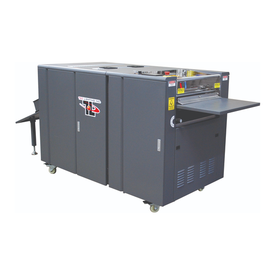
- Page 1 TRU UV Coater OPERATING AND SAFETY MANUAL For the following Models: TRUV-16D, TRUV-21D, TRUV-30A TRUVF-16D, TRUVF-21D, TRUVF-30A S/N_____________________ TEC Lighting, Inc. 555 Vanguard Way Brea, Ca. 92821 www.teclighting.com Phone (714) 529-5068 Fax (714) 529-0344...
- Page 2 Corrections This manual may contain technical inaccuracies or typographical errors due to improvements or changes to the feeder. In the event of major changes to the feeder, TEC Lighting will update and issue a new edition of this manual. Disclaimer This manual goes through the entire operation procedure of the TRU UV Coater.
- Page 3 -Check all three rollers for potential damage from misuse, if caught early preventative measures can be taken to prevent serious, permanent damage. IF ANY PREVENTABLE DAMAGE IS FOUND ON THE MACHINE REPORT IT TO TEC LIGHTING IMMEDIATELY! TEC Lighting, Inc.
-
Page 4: Table Of Contents
Doctor blade Replacement 66-70 28.0 BOM for Feeder 29.0 BOM for UV Coater 71-73 30.0 BOM for UV Dryer 74-76 31.0 Grease Lubrication 32.0 Trouble Shooting Solution Guide TRU UV Coater Safety Kit Conveyor Belting Heating Kit Warranty Validation Form (XCWF) -
Page 5: Safety
7. DO NOT look directly into the UV light; it can cause severe burns to the eyes and skin. You must wear protective UV blocking eyewear. 8. DO NOT make modifications to the machine without written agreement from TEC Lighting. 9. DO NOT leave tools, equipment or any material lying on the machine. -
Page 6: Safety Decals
SECTION 1.2 SAFETY DECALS It is very important that you read, understand and follow all safety guidelines and operating instruction. Any Machine with rotating rollers and UV lighting can be dangerous. Be sure all safety guards are in place and fully secured before operating the system. -
Page 7: General Overview
SECTION 2.0 GENERAL OVERVIEW The purpose of the unit is to transfer UV coating to the sheet in a continuous fashion, either off-line or in-line with your current production processes. Note: Printed material must be 100% dry before sending through the UV coater ... -
Page 8: Description
SECTION 2.1 DESCRIPTION This machine consists of several major sub-assemblies functioning together to instantly “apply” and “dry” or “cure” UV coatings. All TRU UV Coater systems are 100% tested and inspected before shipping. UV COATER/CONVEYOR SYSTEM The sub-assemblies are: Roller drive assembly with adjustment controls ... -
Page 9: Warranty Policy
This does not include physical damage, abuse, neglect, wiring or unauthorized installation. TEC Lighting, Inc. reserves the right to make the final determination of all warranty claims and product dispositions. Tec Lighting Inc. is not responsible for any lost production time due to machine downtime. - Page 10 If customer requires replacement parts sooner, customer needs to provide the shipping account number. All parts must be replaced with manufacture’s original parts. TEC Lighting Inc. reserves the right to make the final determination of all warranty claims and product dispositions. INSPECTION ...
- Page 11 SECTION 4.0 16” ELECTRICAL SPECIFICATIONS Lamp Arc Length: 16” Number of Lamps: Wattage Per Inch: 200 W.P.I. Wattage K.W: 3,200 K.W. Primary Input Voltage: 208-220/240vac 60Hz 1ph Total System Running Amperage: 32A no feeder 40A with feeder Service Disconnect: 40A no feeder. 50A with feeder.
- Page 12 SECTION 4.1 21” ELECTRICAL SPECIFICATIONS Lamp Arc Length: 21” Number of Lamps: Wattage Per Inch: 200 W.P.I. Wattage K.W: 4,200 K.W. Primary Input Voltage: 208-220/240vac 60Hz 1ph Total System Running Amperage: 37A no feeder 46A with feeder Service Disconnect: 50A no feeder. 60A with feeder.
- Page 13 SECTION 4.2 30” ELECTRICAL SPECIFICATIONS Lamp Arc Length: 30” Number of Lamps: Wattage Per Inch: 200 W.P.I. Wattage K.W: 6,000 K.W. Primary Input Voltage: 208-220/240vac 60Hz 3ph Total System Running Amperage: 50A no feeder 55A with feeder Service Disconnect: Conveyor Belt Part No.: BELT-380 UV Lamp: TR30UVL...
-
Page 14: Panel Control Terminology
SECTION 5.0 PANEL CONTROL TERMINOLOGY 1. Coater Speed- Controls the belt and roller speed 2. Feeder Speed- Controls how fast the feeder suction cup picks-up the substrate and deliver into the UV Coater. 3. I.R. Intensity - Controls the heat temperature that is applied to the substrate. 4. - Page 15 SECTION 6.0 PRE SET-UP A. Read and understand all safety warning decals. B. Check for damages caused by shipping – report damages to shipping carrier and your dealer. C. Carefully uncrate your system. A forklift is required. D. Check and ensure that all sheet metal bolts are not loosened from transport vibration. Use proper tools for tightening.
-
Page 16: Catch Tray Station
SECTION 6.2 CATCH TRAY STATION 1) Adjustable Catch Tray station. 2) Insert the LEFT side of the catch tray insertion pin into its holding block. 3) Remove the RIGHT side holding block. Place the block on the insertion pin (as shown). - Page 17 4) Re-attach the holding block into position and secure with screws. 5) Set the supporting legs into position. Make sure the legs are straight. 6) Set the height adjustment per your requirement .
- Page 18 7) Insert the handles threaded stud into paper guide and thru the catch tray slotted hole. 8) On the back side of the catch tray secure with flat washer and hex nut. 9) To lock the handle, push downward. To open, lift up the handle. Adjustment to the hex nut maybe required for locking position.
-
Page 19: Uv Lamp Installation
UV lamps are packaged in its own container, open box and inspect the lamp for shipping damages. Clean UV lamp glass body with TEC Lighting cleaning solution TECAL70. Handle the UV lamp carefully 1) Open the electrical panel door. - Page 20 5) Lift up the extrusion and place on work bench. 6) Rotate the assembly to expose the reflector mirror. NOTE: Extra cleaning of the reflector mirror maybe required, use TEC Lighting cleaning solution TECAL70. Remove the lamp holder supporting block (one side only).
- Page 21 7) Insert the UV Lamp lead wire through the supporting block. Set the UV Lamp end base into supporting block . NOTE: Please be very careful not to add pressure on the UV Lamp. FRAGILE. 8) Re-attach the supporting block and secure with wing nuts.
- Page 22 9) Place the UV lamp into its compartment. Note: There are two guide pins for proper alignment. Make sure the extrusion is fully seated and secured with guide pins. (Guide Pins) 10) Connect the male and female insulated connectors. (both ends)
-
Page 23: I.r. Lamp Inspection
11) Reset UV panel, make sure the fan lead wires don’t get pinched during closer. Unlatch top cover panel carefully lower into position and secure. SECTION 8.0 I.R. LAMP INSPECTION The I.R lamps are pre-assembled inside of the conveyor system compartment. ... - Page 24 3) Check all terminal connections, heat shield alignment and I.R. lamps. 4) Reset I.R. panel, make sure the fan lead wires don’t get pinched during closer. Unlatch top cover panel carefully lower into position and secure.
-
Page 25: Feeder, Pre Set-Up
SECTION 9.0 FEEDER, PRE SET-UP This process only applies to TEC Lighting UV coater with Feeders. After uncrating and removing the plastic wrapping, check for any damages caused by shipping. Refer to section 3.0 Inspection. TRU Coater has two electrical connection to energize the feeder. - Page 26 4) Unpack the paper roller guide. 5) At one end of the roller guide, there are two notches. Each notch should line-up with carriage thumb screw. Secure into position with the thumb screw. 6) Each roller guide should be placed on the green belt as shown in the picture above.
- Page 27 7) Remove the wire ties that hold the table and gear chains. 8) Each feeder is equipped with 3 leveling boards. Your production paper will sit on top of these boards. The amount of boards required, depends on your sheet size. 9) Place your stack of papers on the leveling boards.
- Page 28 11) All feeders are equipped with 2 sets of the paper weight assemblies. Customer has the option to set up 1 or 2 paper weight stations. 12) One station, set up in the center. (as shown). 13) Two stations, set up evenly apart. (as shown).
-
Page 29: Electrical Input Power Hook-Up
SECTION 10.0 ELECTRICAL INPUT POWER HOOK-UP WARNING, ONLY AUTHORIZED SERVICE TECHNICIANS SHOULD DO ALL SERVICE AND REPAIRS. HIGH VOLTAGE AND CURRENT ARE USED TO ENERGIZE THE UV LAMP. Refer to section 4.0, 4.1 and 4.2 for Electrical Specification. 1) Make sure the main power is in the OFF position. Insert your power line thru the electrical port hole. -
Page 30: Uv Coating Set Up
SECTION 11.0 UV COATING SET-UP SAFETY GOGGLES AND GLOVES MUST BE WORN AT ALL TIMES WHEN YOU ARE SETTING UP OR CLEANING THE UV COATER. READ AND UNDERSTAND THE SAFETY DATA SHEET FOR THE UV COATING. 1) Open UV Coating compartment door. 2) Connect the brass fitting hose to the blue or orange tubing. - Page 31 4) Close the pump head, check the tubing for any misalignment or improper installaton. UV Coating may not flow evenly unless the tube is set correctly. 5) Move your 5 or 1 gallon pail of UV coating inside the cabinet. 6) Open your fluid container and insert the larger clear tubing (fluid return).
- Page 32 8) Insert the black tubing into the lid of coating container (as shown). Make sure both tubing’s are secured. 9) Open the plexi-glass cover. The blue and orange tubing faucet should be facing downward between rubber and the metering roller. 10) Double check all tubing hoses are secure.
-
Page 33: Start Up Process
WARNING: High Voltage is engage thru the system. 3) After turning on the system, the touch screen will automatically turn on. The TEC Lighting Logo will for approximately 30 sec. 4) Press the SYSTEM icon switch to the ON position. - Page 34 5) Press the UV LAMP icon switch to the ON position. The UV lamp takes 2.5 minutes warming up before READY. After warm up the exhaust blower will automatically turn on. 6) Open the UV Coating compartment: Engage the Metering roller, turn the knob Metering counterclockwise.
- Page 35 WARNING: THE CONVEYOR SPEED MUST BE AT 6.6 BEFORE TURNING ON THE COATER CLUTCH. WARNING: THIS MACHINE HAS ROTATING ROLLERS AND CAN CAUSE SERIOUS INJURY. 9) Press the COATER CLUTCH icon switch to the ON position. NOTE: The rollers will start turning. 10) Press the UV FLUID PUMP icon switch to the ON position.
- Page 36 If your UV Coater is a hand fed system, you are now ready to start your production run. Continue this process at paragraph 22. NOTE: The process below is for those UV Coaters equipped with Feeders. 12) Carefully move the feeder into its position.
- Page 37 13) Set the feeder to Manual control. Turn and hold the selector switch to TABLE UP position. Your feeder table will rise up. Release the switch, the feeder table will stop. 14) Slowly raise up the stack, Leave approx 1/8 inch gap from the sheet separator and the top sheet.
- Page 38 15) The air suction cups that are not over the paper, must be CLOSED. Pulling upward on the plastic housing will close the air suction. Make sure all suction cups that are over the paper, are OPENED. Pushing downward on the plastic housing will open the air suction.
- Page 39 Note: The sensor is active when the feeder selector switch is in the AUTO position. The sensor will activate the feeder table to rise automatically during the process. The sensor lever has a steel ball to support the paper from improper feeding. 17) Set the Feeder control to AUTO position.
- Page 40 The Feeder has two items that are pre-set, calibrated by Tec Lighting and should be adjusted only if paper thickness changes. Picture 1, Feeder Impression roller: (left & right) control settings for paper thickness. Picture 2. Double sheet detector, prevents double sheeting.
- Page 41 WARNING: THE COATER AND FEEDER HAS ROTATING ROLLERS AND CAN CAUSE SERIOUS INJURY. Refer to section 9, paragraph 4 the paper roller guides and strap. Adjustments maybe required for paper stability. The paper will start moving downward the conveyor system into the UV Coater rollers.
- Page 42 23) Run approximately 5-10 sheets. If your system is equipped with a feeder, turn OFF the Feeder Air Pump. Check the sheets quality finish.
- Page 43 If the finish quality meets your satisfaction and you have an Off Line system, slowly increase the Coater Speed to your production requirement. You are now ready to continue with your production work. Refer to paragraph 24 & 26. If you have a Feeder system, turn ON the Feeder Air Pump switch. Continue this process at paragraph 24-26.
-
Page 44: Shut Down Process
SECTION 13.0 SHUT DOWN PROCESS DANGER: HIGH VOLTAGE AND CURRENT ARE USED TO ENGERGIZE THE UV AND I.R. LAMPS. DO NOT LOOK DIRECTLY AT THE UV LIGHT, WEAR EYE PROTECTION. WARNING: THIS MACHINE HAS ROTATING ROLLERS AND CAN CAUSE SERIOUS INJURY. Note: This shut down process is for equipment with or without Feeder control. - Page 45 4) Turn OFF the UV Fluid Pump. 5) Allow time for the UV Coating to flow off the rollers. Increasing the Coater Speed will help this process. NO UV COATING 6) After UV Coating is completely gone, set the Coating Speed to zero (0). Note: The default speed is 6.6...
- Page 46 7) Turn OFF the Coater Clutch. 8) Open the Plexi-Glass cover and lift up the faucet hose upward. Note: When the plastic cover is opened, an error message will display on the touch screen. This is a Warning message to let you known a safety interlock door is open.
- Page 47 10) Open the UV Coating compartment. METERING Disengage the Metering roller, turn the knob clockwise. Disengage the Impression roller, turn the knob clockwise. IMPRESSION 11) Carefully close the plexi-glass cover. 12) Press the error message icon. The message should disappear. 13) Remove the unwanted stack of paper from the Feeder.
- Page 48 14) Before turning off the system, the UV Lamp must be off. Refer to paragraph 3. 15) Turn OFF System icon switch. 16) Turn OFF the system main power source. You have now completed the shut down process. For roller cleanup, continue to Section 14, UV Coater Cleanup Process.
-
Page 49: Uv Coater Clean-Up Process
Note: Before cleaning allow the excesses UV Coating to drain back into the 5-gallon pail. 1) Make sure your main power is OFF. 2) Carefully open the plexi-glass cover. 3) To clean the rollers you must use Tec Lighting UV wash solution TEC501 and cleaning cloth TEC560027. - Page 50 4) Spray a small amount of UV wash to a clean cloth and wipe off all UV Coating. Clean all 3 rollers: Rubber, Metering and Impression. 5) Cleaning the Doctor Blade with EXTREME CAUTION. Apply a small amount of UV wash to a clean cloth and wipe behind and the front of the doctor blade assembly.
- Page 51 6) Apply a small amount of UV wash to a clean cloth and wipe the lower drain pan. 7) Open the UV Coating compartment. Open the UV pump head, to relief pressure from the tubing. Close the cabinet door. You have now completed the UV Coater Cleanup process.
-
Page 52: Fast Stop Process
SECTION 15.0 FAST STOP PROCESS WARNING: THIS MACHINE HAS ROTATING ROLLERS AND CAN CAUSE SERIOUS INJURY. YOU MUST WEAR SAFETY GOGGLES AND GLOVES AT ALL TIMES WHEN YOU ARE CLEANING THE UV COATING SYSTEM. NEVER leave the rollers engaged for more than 20 minutes, when not in operation. This will cause a flat spot on the rubber roller and affect coating quality. - Page 53 1) Carefully open the plexi-glass cover. Note: After opening the plexi-glass cove an error message will display on the touch screen. This is a Warning message to let you know a safety interlock door is open. 2) Disengage the doctor blade, metering and impression roller. Refer to section 13 paragraph 9-10 3) Pull outward on the jammed paper.
- Page 54 4) Clean up any excess UV Coating that may have spilled on the feed table. 5) After the paper jam has been cleared and feed table is cleaned, Press the red icon bar “Coater Guard Cover Open” The red icon will disappears. 6) Re-engage the doctor blade, metering and impression roller.
- Page 55 9) Press the UV Fluid Pump icon switch to the ON position. If your system has a Feeder system continue to step 10. If your UV Coater is a OFF LINE system, you are now ready to start your production run.
-
Page 56: Error Message
SECTION 16.0 EMERGENCY STOP SHUT DOWN PROCESS This Emergency E-Stop will completely shut down the system except, the exhaust blower. The blower will continue to run for approximately 5 minutes to cool down the UV lamp. There are two E-Stops: one on the UV Coater and one on the Feeder. Refer to Section 18 for Restart Process DO NOT USE THESE E-STOPS FOR NORMAL SHUT OFF PROCESS. -
Page 57: Restart Process
SECTION 18.0 RESTART PROCESS This process will guide you to restart your process after, E-Stop is depressed or opened cabinet door. The E-stop and opened cabinet door will shut down the system completely except the exhaust blower. The blower will continue to run for approximately 5 minutes to cool down the UV lamp. -
Page 58: Coater Restart Process
SECTION 19.0 COATER RESTART PROCESS This process will guide you to restart your process after the coater plexi-glass cover has opened. If this panel is opened during operational, it will shut down the Coater Clutch, UV Fluid pump and the Feeder air pump. NEVER leave the rollers engaged for more than 20 minutes, when not in operation. -
Page 59: Sheet Counter And Uv Lamp Hour Meter
SECTION 20.0 SHEET COUNTER AND UV LAMP HOUR METER These feathers allow you to keep track how many sheets are being process and how many running hours are used on the UV lamp. 1) Press the NEXT icon switch. 2) The touch screen will display the number of sheets ran during your production cycle. -
Page 60: Rubber Roller Replacement
SECTION 23.0 RUBBER ROLLER REPLACEMENT WARNING: THIS MACHINE HAS ROTATING ROLLERS AND CAN CAUSE SERIOUS INJURY. NEVER leave the rollers engaged for more than 20 minutes, when not in operation. This will cause a flat spot on the rubber roller and affect coating quality. 1) Turn OFF main power. - Page 61 6) Remove the socket screw for the roller gear guard. 7) Remove the roller gear guard. 8) Remove the (2) socket screws for bearing holding block. Repeat this step on the opposite side of the roller.
- Page 62 9) Carefully lift the rubber roller out from its supporting holder. After removal, inspect and clean the supporting holder and the impression roller. 10) Unpack the new rubber roller; inspect the rubber roller for any shipping damages. Check the bearing and roller gear. 11) Carefully insert the rubber roller into its supporting holder.
- Page 63 12) Re-attach the bearing holding block, refer to paragraph 8. Secure the bearing with a small amount tension applied with the set screw. 13) Re-attach roller gear guard. (refer to paragraph 6 – 7) and re-attach the drain splash guard (refer to paragraph 5) Note: The drain splash guard must be seated inside the UV Coating drainage port, as shown in picture above.(far right).
-
Page 64: Conveyor Belt Replacement
SECTION 26.0 CONVEYOR BELT REPLACEMENT WARNING: THIS MACHINE HAS ROTATING ROLLERS AND CAN CAUSE SERIOUS INJURY. WARNING: MAKE SURE THE MAIN POWER IS OFF. 1) Loosen the take-up bearing assembly, both ends, turn clock wise. 2) Move the belt to locate the junction connection point. - Page 65 6) Move the conveyor belt to the center of the roller. 7) Slowly engage the take-up bearing assembly, both ends, turning counter clock wise. 8) Set both adjustment rods, approx. to the same dimension. 9) Check the belt, flatness, no curves. Make adjustment for a smooth level surface.
- Page 66 10) Set all controls setting to zero (0). 11) Turn ON the system disconnect switch. (refer to Section 12. paragraph 2-3) 12) Press the SYSTEM icon switch to the ON position. The conveyor belt will automatically start moving. 13) Watch the conveyor belt; make sure the belt doesn’t track off center. Slowly turn UP the coater speed (approx.
-
Page 67: Doctor Blade Replacement
SECTION 27.0 DOCTOR BLADE REPLACMENT WARNING: THIS MACHINE HAS ROTATING ROLLERS AND CAN CAUSE SERIOUS INJURY. NEVER leave the rollers engaged for more than 20 minutes, when not in operation. This will cause a flat spot on the rubber roller and affect coating quality. WARNING: MAKE SURE THE MAIN POWER IS OFF. - Page 68 4) Remove the two (2) mounting screws, both ends. A second person will be helpful to hold one end of the bracket. CAUTION: THE DOCTOR BLADE HAS SHARP EDGES. 5) Carefully lift and remove the doctor blade assembly. CAUTION: THE DOCTOR BLADE HAS SHARP EDGE. 6) Carefully set the doctor blade on the work bench with the aluminum plate facing upward.
- Page 69 7) Carefully loosen all mounting screws. 8) Carefully slide out the old doctor blade. CAUTION: THE DOCTOR BLADE HAS SHARP EDGE. 9) If required, remove the aluminum plate and clean any excess UV Coating from both mounting plates. 10) If removed, replace the aluminum plate and mounting screws, insert the doctor blade back into its holder.
- Page 70 11) There are two (2) different types of doctor blade holders. A) Holder with pins, picture on the left. B) Holder with no pins, picture on the right. 12) The doctor blade with no pins needs to be set at 10mm, as shown above. The doctor blade with slots needs to line-up with the pins on the holder.
- Page 71 14) Reengage the doctor blade, continue turning until the blade is approximately 1/8” inch from the impression roller. 15) Inspect the doctor blade; it must be level with the impression roller. Engage the doctor blade with a soft touch to the impression roller, this will help you to see if any misalignment with the blade.
- Page 72 SECTION 29.0 BILL OF MATERIAL, UV COATER Rubber roller: 16” TR16RR Rubber roller: 21” TR21RR Rubber roller: 30” TR30RR Metering roller: 16” TR16MR Metering roller: 21” TR21MR Metering roller: 30” TR30MR Impression bottom roller: 16” TR16IBR Impression bottom roller: 21” TR21IBR Impression bottom roller: 30”...
- Page 73 Pump head: MOT-050 Fluid black hose : TBG-049 Blue tubing: TBG-035 Orange / Red tubing: TBG-034 12mm Hose fitting: XC-037 16” Plexi-glass cover assembly: 40-5007 21” Plexi-glass cover assembly: 40-5005 30” Plexi-glass cover assembly: 40-5006 White poly Sprocket gear - Chain drive: GR-224 Belt drive: GR-224A Bearing: BRG-051 (2)
- Page 74 Metering roller bearing parts Bearing: BRG-051 (2) Retaining Ring 20mm: RTNG-014 (2) Impression roller bearing parts Gray steel Sprocket gear: GR-226 Bearing: BRG-051 (2) Retaining Ring 20mm: RTNG-014 (2) Retaining Ring 25mm: RTNG-013 Keyway: GR-225...
- Page 75 SECTION 30.0 BILL OF MATERIAL UV DRYER Extrusion assembly TRUV16: TR16EXT Extrusion assembly TRUV21: TR21EXT Extrusion assembly TRUV30: TR30EXT 16” UV LAMP: TR16UVL 21” UV LAMP: TR21UVL 30” UV LAMP: TR30UVL 16” Reflector liner set: TR16RL 21” Reflector liner set: TR21RL 30”...
- Page 76 I.R Cap & Base: XC-035 16” I.R. LAMP: TR16IR 21” I.R. LAMP: TR21IR 30” I.R. LAMP: TR30IR 16” I.R. Reflector shield set: 40-0067 21” I.R. Reflector shield set: 40-0066 30” I.R. Reflector shield set: 40-0065...
- Page 77 16” Conveyor Belt: BELT-425 21” Conveyor Belt: BELT-424 30” Conveyor Belt: BELT-428 16” Conveyor exit roller: TR16CER 21” Conveyor exit roller: TR21CER 30” Conveyor exit roller: TR30CER 16” Conveyor rubber roller: TR16CRR 21” Conveyor rubber roller: TR21CRR 30” Conveyor rubber roller: TR30CRR...
-
Page 78: Grease Lubrication
THIS MACHINE HAS ROTATING ROLLERS AND CAN CAUSE SERIOUS INJURY. Any machinery with movable gears and rotating rollers require lubrication. The TRU UV Coater and Feeder has many movable parts and needs to be greased and lubricated Every 30 days. -
Page 79: Tru Uv Coater Safety Kit
TRU UV COATER SAFETY KIT “TR99SK” Goggle Eye Protective – 1VT70 Disposable Gloves – S-14179L (100 per box) Wipe Cloth – 560027 (2 bags) Lamp Cleaning Solution – M313 Cotton Gloves – S-7892M (2 pairs) ... -
Page 80: Conveyor Belting Heating Kit
CONVEYOR BELT HEATING KIT Repair your conveyor belt within minutes, glue then heat “No major disassembly required” Order number: CBHK (220vac is required) Contact Your Sales Representative For More Information Lighting, Inc. 555 Vanguard Way, Brea, CA. 92821 Ph: (714) 529-5068 Fax:(714) 529-0344... - Page 81 Lighting, Inc. INLINE CARBON FILTER, CF745 TEC Lighting has designed an inline carbon filters system for your UV Coater. The filter scours and cleans the air of foreign particulates, organic compounds and odors. Inline system is equipped with high performance 745 CFM inline fan pack with RC-4/8 premium grade of collie carbon.
-
Page 82: Warranty Validation Form (Xcwf)
TRU UV Coater Warranty Validation Form This form will help ensure that your new TRU UV Coater will be fully covered by its warranty. Please complete this form and return within 14 days from acceptance of the unit. This certifies that the manufacturer or dealer has conducted appropriate training for the owner and / or his representatives on the safe and proper operations of the TRU UV coater.