Table of Contents
Quick Links
Table of Contents

Summary of Contents for Dormakaba Combi B Alarm box
- Page 1 Electronic safe lock Combi B Alarm box Mounting instruction V2.0 - 09/2018...
- Page 2 All rights reserved. No part of this document may be reproduced or used in any form or by any means without prior written permission of dormakaba Schweiz AG. All names and logos of third-party products and services are the property of their respective owners.
-
Page 3: Table Of Contents
Table of contents About this document Purpose and objective Target group Compliance with safety and standard Safety information Intended use Hazard category System overview System description Overall system Wiring Technical data Mechanical components Electrical data Schematics and Layout Circuit diagram Connectors and Component layout Unpacking and checking delivery Checks before installation... -
Page 4: About This Document
About this document Purpose and objective This Mounting Instruction describes the Alarm box for the CB30 electronic safe lock with mechanical redundancy. It gives information on: • The system and components • Technical data • Installation Target group This document exclusively addresses itself to skilled personnel (technicians) trained and authorized by the manufacturer. -
Page 5: Safety Information
Safety information Intended use The purpose of the alarm box is to connect the lock of a safe, vault or data cabinet to an intrusion detection system. Do not modify the alarm box since it will impair the security and safety of the unit. -
Page 6: System Overview
System overview Overall system • Combi B lock • Combi B input unit • Alarm box • Intrusion detection system (IDS) Mounting instruction Alarm box V2.0... -
Page 7: System Description
Overall system To integrate the Combi B lock into a VdS-compliant intrusion detection system, the Combi B alarm box must be used. The box allows transmission of a threat alert (silent alarm) and of the status message of the bolt lock to an intrusion detection system (IDS). -
Page 8: Technical Data
Technical data Mechanical components Technical data Component property Dimensions 85 mm x 85 mm x 26 mm Environmental class System of protection IP 30 Electrical data Connection Property Power supply 12V DC ±10% / max. 80mA Bolt switching contact 30V DC/ < 0.1A Tamper switch/cover 30V DC/ <... -
Page 9: Schematics And Layout
Schematics and Layout Circuit diagram Mounting instruction Alarm box V2.0... -
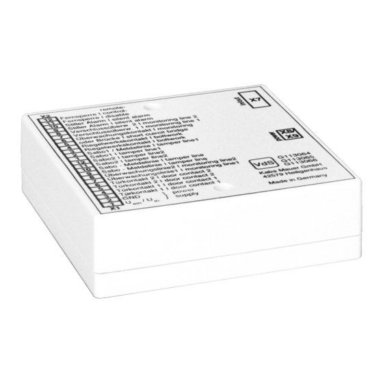
Page 10: Connectors And Component Layout
Connectors and Component layout Mounting instruction Alarm box V2.0... -
Page 11: Unpacking And Checking Delivery
Unpacking and checking delivery Checks before installation Requirements: • Unpack the delivery. • Make sure that the content is complete. Make sure that the delivery includes: • Alarm box • Connecting cable lock 8 terminal • Connecting cable lock 4 terminal •... -
Page 12: Installation
"Power" socket at the Combi B lock. The Combi B alarm box must be supplied with power from an external voltage source. Either the KMH "Combi B alarm box power pack“ (article number 3002501230) or an alternative voltage source of the required specifications of 9-15 volts DC and max. -
Page 13: Opening Monitoring Line
Opening monitoring line Terminals: X1.3 to X1.8, see Connectors Line resistors, R101, R103 or R104, see Schematics Depending on the structure and design of the secure storage unit, the door contacts, monitoring lines and tamper lines can be looped in or used as separate lines. -
Page 14: Silent Alarm
Silent alarm Terminals: X2.9 and X2.10, see Connectors Line resistor R108, see Schematics Short-circuit bridge for variant A or alternative B on R109, see Schematics (variant A: switch contact normally closed; variant B: switch contact normally open) When the silent alarm is set at the lock for the first time, the output is switched once for four seconds for checking purposes (for the terminals and resistors, see above). -
Page 15: Input
Input Terminals: X2.11 and X2.12, see Connectors Series resistor R108 for variant A or B, as desired, see Schematics NOTICE If a master code has not yet been activated at the lock, but the installer code is still operating, no alarm will be triggered! More details can be found in the operating instructions chapter 8. - Page 16 Depending on which functions are active (inactive ex works, others set via the PC software), the installation must be checked as follows: • To check the remote control disable, energizing must be carried out as described in chapter 4.2 and an opening in-tent must be carried out at the lock (see operating instructions chapters 8 and 10).
- Page 17 Mounting instruction Alarm box V2.0...
- Page 18 Mounting instruction Alarm box V2.0...
- Page 19 Mounting instruction Alarm box V2.0...
- Page 20 – neither in digital nor in photographic form without prior written permission of dormakaba Schweiz AG. © by dormakaba Schweiz AG. dormakaba Schweiz AG Mühlebühlstrasse 23 8620 Wetzikon T: +41 44 931 61 11 www.dormakaba.com II_Alarmbox_CB30, September 2018 Art.Nr.