
Related Manuals for Fujitsu 8FX MB2146-510-01-E


Summary of Contents for Fujitsu 8FX MB2146-510-01-E
- Page 1 FUJITSU SEMICONDUCTOR SS702-00002-1v0-E SUPPORT SYSTEM New 8FX Family 8-bit MICROCONTROLLER MB95560H/570H/580H Series STARTER KIT MB2146-510-01-E SETUP GUIDE...
- Page 2 *1 : Referred below as the “Starter Kit”. *2 : Referred below as the “BGMA”. *3 : Referred below as the “EV-Board”. *4 : F MC is the abbreviation of FUJITSU Flexible Microcontroller. *5 : Referred below as the “S ”. OFTUNE is a trademark of Fujitsu Semiconductor Limited, Japan.
- Page 3 ■ Caution of the products described in this document The following precautions apply to the product described in this manual. Indicates a potentially hazardous situation which could result in death or serious WARNING injury and/or a fault in the user’s system if the product is not used correctly. Before performing any operation described in this manual, turn off all the power Electric shock, supplies to the system.
- Page 4 (i.e., submersible repeater and artificial satellite). Please note that FUJITSU SEMICONDUCTOR will not be liable against you and/or any third party for any claims or damages arising in connection with above-mentioned uses of the products.
-
Page 5: Product Overview
1. Product Overview This product is a set of Starter Kit of MB95560H/570H/580H series. It is composed of a BGMA and an EV-board. Combining the S Workbench on PC, the Starter kit enables the quick start of de- OFTUNE velopment before the user system is ready. 1.1 Objective and Deliverable The Starter kit provides users a complete development platform. -
Page 6: Hardware Setup
1.4 Feature The MB95560H/570H/580H Series starter kit is the best for a performance and functional evaluation, and a check of operation before including MB95560H/570H/580H Series in a user's system. Below, the feature of the BGM debugger for MB95560H/570H/580H Series is shown. •... -
Page 7: Function List
2. BGMA Manual 2.1 BGMA Overview Below is the close look of the BGMA. It provides a debug platform for the New 8FX MCU (except MB95200H/210H/220H) in a small size (58mm (W) × 90mm (D) × 20mm (H)) . BGM Adaptor: MB2146-07-E BGM Adaptor BGM Adaptor Power LED BGM Adaptor status LED... - Page 8 2.3 IDC10 Interface Description Pin Number Pin Name Description UVCC Target MCU Vcc Target MCU Vss RSTIN Target MCU reset input RSTOUT Target MCU reset output Reserved POUT3V Supply 3V power out, when this function enabled Reserved Target MCU debug pin Reserved Reserved 2.4 BGM Adapter USB Configuration...
- Page 9 Select “Install from a list or specific location (Advanced)", then click “Next", Figure 4 Install BGMA in Windows (2) Select “…\Drivers” from the folder where SOFTUNE is installed, click “Next”, Figure5 Install BGMA in Windows (3)
- Page 10 Select BGMA (MB2146-07) as displayed below, and then click “Next”, Figure 6 Install BGMA in Windows (4) Windows will install the driver automatically. Click “Finish” after the driver has completed the installation normally. Then users can find the BGMA is recognized as MB2146-07 in Windows system.
-
Page 11: Led Description
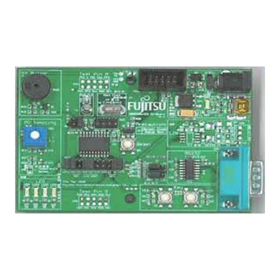
2.5 LED Description First, only plug USB cable to PC, checking the Power LED on BGMA turns Green. Refer to Figure 8. USB Plugged to PC Green Figure 8 BGMA Power LED (1) Second, plug IDC10 cable to the EV-board (target MCU board), then turn on EV-board. After that check Power LED on the BGMA turns Orange. - Page 12 3. EV board Introduction 3.1 EV board Overview MB95560 MCU EV-board is provided as a user-friendly introductory and evaluation platform for the MB95560H/570H/580H MCU Family microcontrollers. Figure 10 below is a close look of EV- board. Debug Interface to BGMA Jumpers left open when debug Buzzer circuit Power supply either...
- Page 13 3.2 Function List The EV-board consists of a board and a sample firmware. The board provides a useful platform for using the MCU and its peripherals. It is a useful development platform together with a BGMA and . It features the following functions, OFTUNE •...
- Page 14 3.3 EV-board Schematic Figure 11 EV-board Schematic...
- Page 15 3.4 HW Module Description and Jumper settings 3.4.1 Power Module EV-board has 4 kinds of power supply for user to choose. Please read below instructions before us- ing. • DC Adaptor: 9V DC: Output voltage: 9V Connection: Connector (CN6) • Battery: QTY: 4PCS;...
-
Page 16: Clock Settings
3.4.2 BGMA Interface To start the debug using a BGMA, users shall connect IDC10 socket from the BGMA to CN1 on an EV-board, and J2 shall be closed to enable reset key S3. Refer to Figure 13. Figure 13 Debug Interface Table 2 J2 Setting MCU Mode Header name... -
Page 17: Led Module
3.4.5 A/D Module VR1 and VR3 are to demonstrate a MCU A/D converter usage. Select VR1 or VR3 by the following table. VR1 is connected to MCU A/D channel 1, and VR3 is connected to MCU A/D channel 0. Table 5 SW2 A/D Setting MCU Mode Header name Settings... -
Page 18: Key Module
3.4.7 Key Module Key S1 and key S2 are provided to demonstrate an external interrupt function. Enable these two keys by the following table. Key S1 is connected to external Int7, and key S2 is connected to external Int6. Table 7 SW2 Key Setting Modules Header name Settings... -
Page 19: Topic List
4. Sample Code Manual 4.1 Topic List The following sample codes are provided with MB95560H/570H/580H MCU Starter Kit, • IO_LED project In this example, the LED2 will be twinkle. • A/D_Potentiometer project In this example, the 3 LEDs will display “on” or “off” according to the arrow direction of VR3. •... -
Page 20: Project Structure
4.2 Project Structure The Sample code is organized by the following structure in each project. Here take IO_LED project for example shown in Figure 14. Figure 14 I/O_LED Project Structure 4.3 Source Code File Description Six files are available in each sample code source code folder shown below, Figure 15 Source Code Files... - Page 21 4.3.1 Header Files The MB95560.h and the _f2mc8fx.h are header files, included MB95560H/570H/580H MCU I/O registers definition; Here take PDR0 for example. In MB95560.h, PDR0 is defined as below. /* REGISTER BIT STRUCTURES */ #ifdef __IO_DEFINE #pragma segment IO=IO_PDR0, locate=0x0 #endif typedef union { __BYTE...
- Page 22 4.3.2 Startup.asm File The Startup.asm is the MB95560H/570H/580H MCU initialization file including stack settings, reg- ister bank settings and watchdog settings etc; 4.3.3 Vectors.c File. The Vectors.c contains the MB95560H/570H/580H MCU Interrupt vectors definition. User can pre-set all interrupt control registers in function InitIrqLevels(). It can be used to set all in- terrupt priorities in static applications.
- Page 23 5. Development Platform Quick Start 5.1 Tools Setup Sequence Start the debugging system in the following sequence: • Connect a BGMA to the PC using a USB cable, confirm the LED on the BGMA is Green; • Connect an EV-board to BGMA IDC10 socket; •...
- Page 24 SS702-00002-1v0-E FUJITSU SEMICONDUCTOR • SUPPORT SYSYEM New 8FX Family 8-bit MICROCONTROLLER MB95560H/570H/580H Series STARTER KIT MB2146-510-01-E SETUP GUIDE November 2011 the first edition Published FUJITSU SEMICONDUCTOR LIMITED Edited Sales Promotion Department...