
Related Manuals for Kalkomat BOXER 5


Summary of Contents for Kalkomat BOXER 5
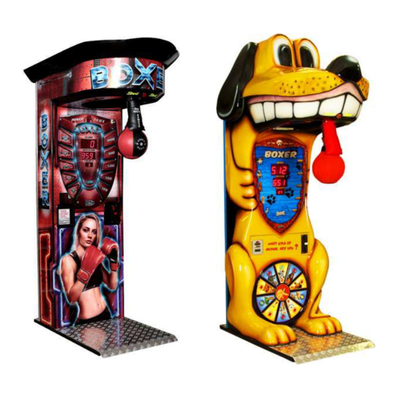
- Page 1 ____________________________________________________________ KALKOMAT ____________________________________________________________ BOXER 5 Punch-Force measuring machine Technical Information Rev. 1.2...
- Page 2 INDEX Introduction ................. 4 Technical Data ................4 Assembly/Construction description ..........4 Transport ..................5 Installation .................. 6 Usage instructions ............... 6 Maintenance check list, problem prevention and day-to-day fixes ................... 7 Potential problems and their resolution........10 Main board layout and setting up the machine ......12 MAINBOARD DISPLAY MENU - CHANGING SETTINGS ...
- Page 3 LUCKY1CREDITS ......................23 LUCKY1TICKETS ......................23 LUCKY1PRINTER ......................23 LUCKY1BALL ....................... 23 LUCKY2CREDITS ......................24 LUCKY2TICKETS ......................24 LUCKY2PRINTER ......................24 LUCKY2BALL ....................... 24 LUCKY NUMBER 1 ......................24 LUCKY NUMBER 2 ......................24 RECORD ...................... 24 RECORDCREDITS ......................24 RECORDTICKETS ......................
-
Page 4: Technical Data
Introduction Main purpose of this Technical Information is to: - familiarize user with machine construction, - provide proper setup parameters, installation and power line hookup, - familiarize user with proper and safe usage procedures, exploitation and conservation. WARNING: USER MUST FOLLOW ALL GUIDELINES INCLUDED IN THIS DOCUMENT FOR SAFE AND LONG LASTING MACHINE USAGE. - Page 5 The key component is a mother board (electronic board) placed inside boxer’s body (block schematics drawing # 1) to which mechanical elements and user interface components are connected. Electric /electronic part contains following: - measuring mechanism – consists of sending and receiving diodes that measure blade fly speed thru assembly, - verbal information mechanism –...
-
Page 6: Installation
Installation Machine after being taken out of the box should be placed in vertical position and base should be leveled. To level the machine appropriate tools should be used (exp. laser level or typical manual construction heavy duty level). Turning several screws under the base allows level adjustment. - Page 7 Maintenance check list, problem prevention and day-to-day fixes Every two weeks (recommended): - check the air pressure of the bag. It should be NO MORE than 2psi, - check if the bag is not rotating about its own axis. If it is, see point d) in this section, - check the position of the arm protector.
- Page 8 c) Maintenance of mechanism and regulating spring Periodically (once a month or more often, or if the lowering speed of punching bag is fairly low) all moving elements should be rubbed / sprayed with WD-40 or grease. If punching bag lowers slowly or too fast one should check if spring is properly stretched.
- Page 9 h) Position of the arm protector. The position of the arm protector should be like on the picture below: DO NOT PLAY THE GAME WITHOUT PROPERLY PLACED ARM PROTECTOR. The following two pictures illustrate an improper setup of the punching bag. NEVER leave the machine in this state. The picture on the left shows the arm protector placed too high.
- Page 10 Potential problems and their resolution. Main board is not functioning: Check connection between transformer and the main board. Make sure that connectors are well seated. If both “POWER” diodes are not lit up: check connection/ power between main board and transformer. If one “POWER” diode is lit up, main board is faulty.
- Page 11 Button START is not functioning: Check for main board cable connection. Check switch/button cable connection. Power supply is refusing to work: Check if “car” fuse in main board (left bottom) is not burned (30 A, green). Check if transformer cable is correctly hooked up to power supply socket.
- Page 12 Main board layout and setting up the machine Main Board Layout (Back Side)
- Page 13 COIN – connector for coin OPTIONS – service settings acceptor switch board BILL – connector for bill BOXER TEST – for acceptor manual Boxer solenoid test LED 4, LED 5 – front panel KICKER TEST – for backlight manual Kicker solenoid test POWER INPUT –...
- Page 14 Main Board Layout (Front) UPPER DISPLAY - shows player’s current score. MIDDLE DISPLAY - shows highest score. BOTTOM DISPLAY - shows current number of credits.
- Page 15 Dip Switch 1-8 (S1) Dip switches 1-8 Switch #1 Not used (diagnostic function only). Switch #2 When “ON”, machine is set for free punch. Switch #3 Not used Switch #4 When “ON”, the highest score for each game will be reset after you push the “START”...
- Page 16 MAINBOARD DISPLAY MENU - CHANGING SETTINGS To change any settings and check counters, buttons (arrows) ENTER (up) and (down), (left) and (center button) need to be used. All information will be shown on the LCD display. If the display is black, use left button to lighten up the display.
- Page 17 BONUS POINTS 2 0..250 BONUS CREDITS 2 0..250 TD. ON / OFF ON, OFF CREDITTICKETS 0..5 RECORDTICKETS OFF, 1..20 BREAKING POINT 0..990 TICKET FIRST TICKET 0..20 DISPENSER TICKET RANGE 10..100 NUMBER OF TICKET OFF, 1..5 TICKETS COUNTER counter TD LOAD SERVICE WHEEL OF Not used FORTUNE...
- Page 18 TIME DISPL RELAX OFF, 10s..3h DIAGNOSTIC BALL DOWN, SENSOR TEST HI LO MODE BALL UP It depends on the setting of the function: FACTORY SETTINGS/ CRED.NATION.SET Do not change. COUNTERS SHORT COUNTER: Temporary counter of points. 1 point = 0,25 $. You can reset it to 0000 by pushing “ENTER”, then pushing ↑...
- Page 19 CREDITS RECORDCREDITS Allows to set number of credits given for breaking a record. POINTSCREDIT: How many credits are needed for one game (how much is a game worth). Example: 1 game is worth 1 $ (4 points), so the POINTS-> CREDITS will be set to 4.
- Page 20 If you want to turn the ticket dispenser off, set this option to 0. CREDITTICKETS: Sets how many tickets are given for 1 credit (range from 0-5). RECORDTICKETS: Sets how many tickets are given for breaking the record (range from 0-20).
- Page 21 BELOW 2 EXAMPLES: ESULT ON ESULT ON ICKETS ICKETS DISPLAY DISPLAY BREAKING POINT BREAKING POINT = 600 FIRST TICKET = 0 FIRST TICKET = 10 TICKET RANGE =40 TICKET RANGE = 40 NUMBER OF TICKET = 1 NUMBER OF TICKET...
- Page 22 WHEEL OF FORTUNE Function unavailable. PRIZE Nx100 Nx100CREDITS Sets bonus credits for a player gained after scoring multiples of 100, e.g. score is 200, 300, 800. To turn this option off, while in setting mode, keep button pressed until display shows OFF. Nx100TICKETS Option.
- Page 23 Nx111TICKETS Option. Sets number of tickets gained after scoring multiples of 111, e.g. score is 222, 333, 888. Nx111PRINTER Option. Sets number printed on thermal printer after scoring multiples of 111, e.g. score is 222, 333, 888. Nx111BALL Sets number of surprise balls gained after scoring multiples of 111, e.g.
- Page 24 LUCKY2CREDITS Sets bonus credits for a player gained after scoring value of LUCKY NUMBER 2. To turn this option off, keep button pressed until display shows OFF. LUCKY2TICKETS Sets number of tickets a player gets after scoring LUCKY NUMBER LUCKY2PRINTER Sets number printed on thermal printer after scoring LUCKY NUMBER 2.
- Page 25 RECORDPRINTER Allows to set prize number of a prize given for breaking a record (which will be printed on thermal printer). RECORDBALL Allows to set number of balls given for breaking a record. UNAVAILAB. RECORD Sets record value that cannot be beaten. NUMBER NUMBER Setting score value for ball give-out.
-
Page 26: Diagnostic Mode
TIME VOICE RELAX Used by manufacturer. TIME DISPL RELAX Used by manufacturer. DIAGNOSTIC MODE SENSOR TEST HI LO Testing of the sensor. While the punching bag is in the vertical position - the display shows "BALL DOWN". While the punching bag is in the horizontal position - display shows "BALL UP”. - Page 27 12. Set up and maintenance instructions How to change the punching bag Changing the punching bag is required in some cases. Lower the bag arm as in the play mode. Take off the front protector and unscrew the top nut using 19 mm wrench (use wrench with a ratchet). This will release the bag assembly.
- Page 28 If it is secured tight enough, then finish by unscrewing the second nut until it tightens on the metal arm. How to release the punching bag manually Sometimes it is necessary to release the punching bag when the machine has no power. This can still be done manually. You must reach over the bag and find the mechanical hammer holding the entire arm in position.
- Page 29 How to change the fuse in the main switch Locate the power cord connection on the back of the machine. The fuse can be found hidden between the power cord socket and the main ON/OFF switch. In order to replace it, use a flat screwdriver to pry open the fuse holder and pull it out.
- Page 30 ILLUMINATED START BUTTON The illuminated START button is connected with both, the white and the red connectors. The red connectors are stick on the sides, while the whites are on the back and upper side of the button. See the photo below for the proper connection.
- Page 31 Date of Service Punching bag condition Punching bag pressure Arm protector condition Arm protector position Legibility of disclaimer Legibility of instruction Level of machine Grease on mechanism Bulbs Button Bill and coin validators Safe condition (Yes/No) If not working or condition not safe for use what was replaced Comments...