Quick Links
Installation Instructions
Model OOHC941
Multi-Criteria Fire/CO Detector
UL268 7th edition listed
These instructions are written in accordance with the
installation guidelines of NFPA 72, National Fire Alarm
Code and CAN/ULC-S524, The Installation of Fire
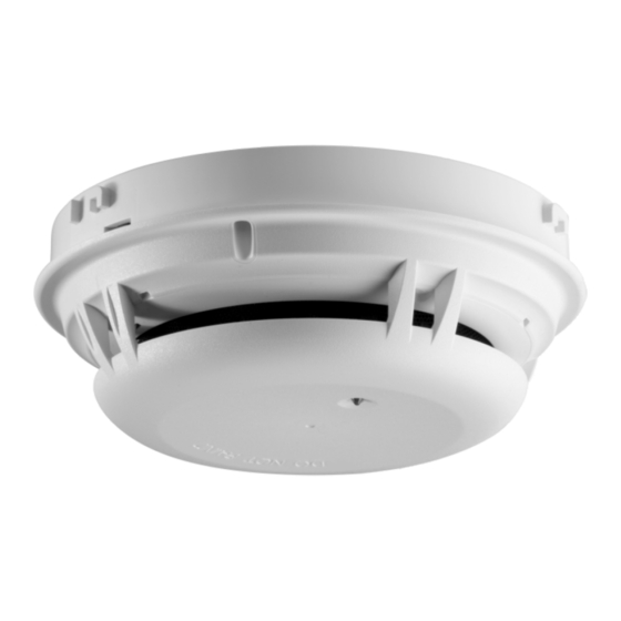
Alarm Systems. The model OOHC941 detector (as
shown in Figure 1) meets the VEWFD (Very Early
Warning Fire Detector) classification and sensitivity
requirements of NFPA 76 (Standard for the Fire
Protection
of
Telecommunications
incorporating a programmable "Alert" (Pre-Alarm)
sensitivity threshold of 0.2%/ft obscuration and an
"Alarm" sensitivity threshold of 1.0%/ft obscuration.
CAUTION
DO NOT install this detection device until all construction
is completed.
DO NOT store this detection device where it can be
contaminated by dirt, dust, or humidity.
DETECTOR PLACEMENT
Although no specific spacings are set for the detectors
used for a clean air application, for multi-criteria fire
detection use 30-foot center spacing (900 sq ft) from
NFPA 72 initiating devices chapter, if practical, as a
guide or starting point for a detector installation layout.
This spacing, however, is based on ideal conditions–
smooth ceiling, no air movement, and no physical
obstructions.
In
some
considerably less area is protected adequately by each
smoke detector. This is why it is mandatory to closely
follow the installation drawings. In all installations place
the detector on the ceiling, a minimum of 6 inches from
a side wall, or on a wall, 12 inches from the ceiling. For
CO
gas
detection
installation requirements in NFPA 72 for Installation of
Carbon Monoxide Detection and Warning Equipment.
A6V10324661_en--_m
2020-08-28
Facilities)
applications,
therefore,
applications,
follow
detector
For thermal detection, use the matrix below:
Spacing, Feet Temperature Rating, °F With/without Guard Model
135, 145, 155, 165, 175
50
60
135, 145, 155, 165, 175
70
135, 145
Drawings provided or approved by Siemens Industry,
Inc., or by its authorized distributors are extremely
important. The detector placements shown on these
drawings were chosen after a careful evaluation of the
area that is protected. Such factors as air currents,
temperature, humidity, pressure, and the nature of the
fire load were carefully considered. Especially noted
were the room or area configuration and the type of
ceiling (sloped or flat, smooth or beamed). Siemens
Industry, Inc.'s extensive experience in the design of the
system assures the best detector placement by following
these drawings. Sound engineering judgment by
qualified personnel must be followed.
TO AVOID NUISANCE ALARMS
Do not locate the detectors where excessive smoke
concentrations exist under normal conditions, or in areas
of prolonged high relative humidity where condensation
occurs.
Do not locate the detectors next to an oil burner, or
garage where exhaust fumes can trigger an alarm. Other
causes of false alarm are dust accumulation, heavy
concentrations of steam, heavy pipe or cigar smoke, and
certain aerosol sprays.
Figure 1
With and without STI Guard
SIEMENS Industry, Inc.
Smart Infrastructure

Related Manuals for Siemens OOHC941


Summary of Contents for Siemens OOHC941
- Page 1 NFPA 72, National Fire Alarm Code and CAN/ULC-S524, The Installation of Fire Spacing, Feet Temperature Rating, °F With/without Guard Model Alarm Systems. The model OOHC941 detector (as 135, 145, 155, 165, 175 shown in Figure 1) meets the VEWFD (Very Early...
- Page 2 Each detector provides pre-programmed parameter sets beam, suspended, level, sloped and peaked ceilings. which can be selected by the panel. The OOHC941 TEMPERATURE – HUMIDITY – PRESSURE – AIR provides three different alarm channels: the multi-criteria...
- Page 3 When the OOHC941 is wired in polarity insensitive mode, Line -6 and -5 can be either line of the loop. When the OOHC941 is wired for Isolator mode, the positive line needs to be connected to 1b and the negative line to 6. The next device needs to be connected to 1b and 5.
- Page 4 Duct w/CO Smoke detection in duct with CO support. High air velocity, dirty, dusty, humid, wide temperature swings. OOHC941 CO Life Safety Profile Balanced US1 The Balanced US1 parameter set meets UL2075 and fulfills sensitivity requirements from UL2034, CSA 6.19-1, and CAN/ULC-S588.
- Page 5 SUPERVISED AND POWER LIMITED TO NEXT BASE * OOHC941 is a polarity insensitive detector. Line 1 and Line 2 can be either line of the loop. ** The relay contacts are shown after System reset, which represents the non-alarm condition.
- Page 6 (concentration) level. * This test is simply used to ensure that smoke can enter The OOHC941 detectors can also be tested individually the sensing chamber and alarm the control panel when using the DPU. Refer to the DPU Manual, P/N 315- the detector reaches the programmed obscuration 033260.
-
Page 7: Maintenance
Method to configure the detector’s special application sensitivity: The detector default sensitivity is for a standard “office” environment. For programming and to select the special application setting / profile (Telecommunications) refer to the specific Siemens compatible fire alarm control panel operation manual. - Page 8 Siemens Industry, Inc. Siemens Canada Limited Smart Infrastructure Smart Infrastructure 8, Fernwood Road 2 Kenview Boulevard Florham Park, New Jersey 07932 Brampton, Ontario L6T 5E4 © Siemens Industry, Inc. www.siemens.com/buildingtechnologies Canada Data and design subject to change without notice. A6V10324661_en--_m P/N A5Q00044520...