Cisco ASR 5000 Installation Procedure
Installation procedure overview
Hide thumbs
Also See for ASR 5000:
- Administration manual (466 pages) ,
- Installation manual (294 pages) ,
- Installation manual (18 pages)
Quick Links
Installation Procedure Overview
This chapter briefly describes the steps and tools that are required for the physical installation of the chassis.
It includes the following sections:
•
Chassis Components, page 2
•
Installation at a Glance, page 3
•
Required Tools and Equipment, page 4
•
Site Prerequisites, page 5
•
•
ASR 5000 Installation Guide
1

Related Manuals for Cisco ASR 5000


Summary of Contents for Cisco ASR 5000
-
Page 1: Table Of Contents
Chassis Components, page 2 • Installation at a Glance, page 3 • Required Tools and Equipment, page 4 • Site Prerequisites, page 5 • Protecting Against Electro-static Discharge, page 5 • Federal Communications Commission Warning, page 6 ASR 5000 Installation Guide... -
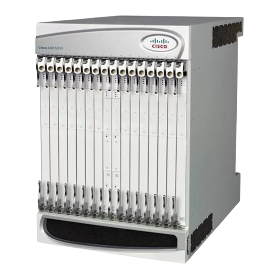
Page 2: Chassis Components
Installation Procedure Overview Chassis Components Chassis Components The following graphic and table illustrate the chassis and describe its subcomponents. Figure 1: ASR 5000 Chassis and Sub-components Table 1: Chassis and Sub-component Identification Key Item Description Chassis: Supports 16 front-loading slots for application cards and 32 rear-loading slots for line cards. -
Page 3: Installation At A Glance
Installation at a Glance The list below summarizes the installation process for the chassis. Unpacking instructions are not provided in this document. Please refer to the Unpacking the ASR 5000 Note Chassis document shipped with the system, for information and instructions on this topic. The chassis and cards are shipped separately. -
Page 4: Required Tools And Equipment
• A computer or terminal server with a 9-pin RS-232C serial port, or 25-to-9-pin male RS-232C adapter. It will be connected to the SPIO's Console port for accessing the command line interface (CLI) for initial system configuration. ASR 5000 Installation Guide... -
Page 5: Site Prerequisites
Clearance Adequate clearance must be maintained at the front and rear of the ASR 5000 chassis to assure proper air flow and allow maintenance access for the installation, removal and replacement of components. The recommended clearance is 30 to 36 inches (76 to 92 centimeters) at the front and rear of the chassis. -
Page 6: Federal Communications Commission Warning
Figure 2: Location of Chassis ESD Jacks Federal Communications Commission Warning This device complies with the limits for a Class A digital device, pursuant to Part 15 of the FCC Rules and Regulations. Operation is subject to the following two conditions: ASR 5000 Installation Guide... - Page 7 Modifications to this product not authorized by Cisco could void the FCC approval and negate your authority to operate the product.
- Page 8 Installation Procedure Overview Laser Notice ASR 5000 Installation Guide...