
Related Manuals for Eaton Crouse-Hinds MTL GECMA WS Series

Summary of Contents for Eaton Crouse-Hinds MTL GECMA WS Series
- Page 1 DRAFT - 07 March 2016 Instruction manual September 2016 MTL HMI and visualisation INM MTL GECMA WS display rev 2 MTL GECMA WS display modules Modular high-resolution display panels for MTL GECMA work stations...
-
Page 2: Foreword
IEC 60079-14. The information in the IECEx or EC-type examination certificate should be fully adhered to. If you have any questions or require technical support, please contact: Eaton’s Crouse-Hinds division GECMA Components electronic GmbH Heinrich-Hertz-Strasse 12... -
Page 3: Table Of Contents
DRAFT - 07 March 2016 CONTENTS FOREWORD . . . . . . . . . . . . . . . . . . . . . . . . . . . . . . . . . . . . . . . . . . . . . . . . . . . . . . . . . . . . . . . 2 DECLARATION OF CONFORMITY . -
Page 4: General Reference
DRAFT - 07 March 2016 GENERAL REFERENCE 3 .1 General safety information The following methods are used in this manual to alert the user to important information:- NOTE: These are used to give general information to ensure correct operation. IMPORTANT: These are used to indicate information that is important to the user. -
Page 5: Provisions For General Operational Safety
DRAFT - 07 March 2016 3 .2 Provisions for general operational safety 3 .3 Application The MTL GECMA 19, 22 and 24 WS display modules are individually certified and designed for industrial use in the potentially explosive atmospheres of Zone 1 and Zone 2. - Page 6 DRAFT - 07 March 2016 Installation a. The installation must comply with the appropriate European, national and local regulations, which may include reference to the IEC code of practice IEC 60079-14. In addition, particular industries or end users may have specific requirements relating to the safety of their installations and these requirements should also be met.
-
Page 7: Safety Provisions
DRAFT - 07 March 2016 Marking Each device is marked in compliance with the Directive and CE marked with the Notified Body Identification Number. This information applies to the MTL GECMA WS display module manufactured during or after the year 2015. Model MTL Gecma Display Module yy Certification Code... -
Page 8: Errors And Overloading
DRAFT - 07 March 2016 • The installation and commissioning may only be performed by professional personnel who are trained according to the regulations, standards and guidelines applicable here. • Only devices which correspond to the electrical characteristics of the IECEx or EC type examination certificate or the operating instructions may be connected. -
Page 9: Overview
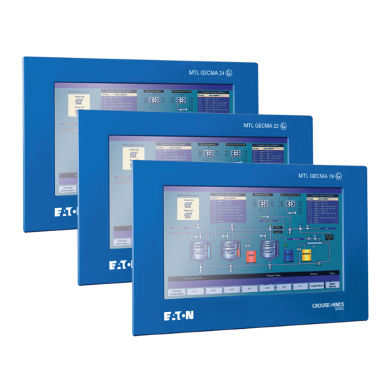
DRAFT - 07 March 2016 OVERVIEW The MTL GECMA 19, 22 and 24 WS display modules are high-resolution graphical panels specifically designed for use in hazardous areas. They are designed to be accompanied by other MTL GECMA modules that will normally consist of, at least, a power supply and a communications (COMs) module –... -
Page 10: Technical Data
DRAFT - 07 March 2016 5 .1 Technical Data: Designation MTL GECMA 19 MTL GECMA 22 MTL GECMA 24 Screen Size 19” 21.5” 24“ Display Type TFT with 16 million colours Resolution 1280 x 1024 (5 : 4) - 1920 x 1080 (16 : 9) - 1920 x 1200 (16 : 10) - lower resolutions are lower resolutions are... -
Page 11: Installation
DRAFT - 07 March 2016 INSTALLATION 6 .1 General information IMPORTANT: Do not install the terminal where the display screen will be subjected to direct sunlight. Regular exposure to ultra-violet (UV) rays will reduce the lifetime of the TFT display panel. Speak to your MTL GECMA representative if you need further guidance on this matter. -
Page 12: Mounting
DRAFT - 07 March 2016 6 .2 .2 Mounting NOTE: It is suggested that two persons are used to mount the display module. One at the front of the panel to hold it in position safely and one at the rear to fit any necessary mounting brackets and securing nuts. -
Page 13: Electrical Dc Power
DRAFT - 07 March 2016 6 .3 .1 Electrical DC power Electrical DC power must be supplied from the MTL GECMA WS AC or DC PSU module, both of which are Ex certified for use in Zone 1 hazardous areas. The MTL GECMA WS PSU modules are designed to mount on the rear of the display module. -
Page 14: Touch-Screen Interface Connection
DRAFT - 07 March 2016 Fibre Optic RS232 J706 USB1 USB2 USB3 USB4 J702 J402 J403 J404 J405 J703 VIDEO J503 SW501 J302 6 .3 .3 Touch-screen interface connection If the touch-screen feature is being used, a connection must be made to the COM module. -
Page 15: Replacing An Mtl Gecma Ws Display Module
DRAFT - 07 March 2016 REPLACING AN MTL GECMA WS DISPLAY MODULE In the event that a MTL GECMA WS display module has to be replaced, this section explains the steps necessary to remove an existing display and fit a replacement. For further details refer to the overall system instruction manual. - Page 16 DRAFT - 07 March 2016 Mounting stud hole positions ‘A’ (x4) Terminal cover plate fixing screws ‘B’ (x4) Power in COM power Display power 2. Referring to the diagram below, use a 3mm flat-bladed screwdriver to loosen the screw terminals for the incoming power wiring terminals on the left of the terminal aperture and withdraw the wires from the terminals.
-
Page 17: Removing The Mtl Gecma Rt Com Module
DRAFT - 07 March 2016 8 .3 Removing the MTL GECMA COM module The picture below provides a view of the electrical and fibre-optic connectors for the RT COM module to be removed. Other COM modules may look slightly different. Refer to the appropriate COM module manual for more information. -
Page 18: Removing The Mtl Gecma Ws Display Module
DRAFT - 07 March 2016 8 .4 Removing the MTL GECMA WS Display module The display module is now clear of all other fittings and can be prepared for removal. IMPORTANT If the display is still upright in the enclosure then an additional person should be positioned at the front of the enclosure to support the display during its removal. -
Page 19: Re-Installing The Gecma Rt Com Module
DRAFT - 07 March 2016 8 .6 Re-installing the GECMA COM module The replacement of the COM module is effectively a reversal of the removal process. 1. Ensure the rear of the display module is cleared of any small items or contaminants and the underside of the COM module is similarly clean before mounting the COM module onto the six mounting studs attached to the rear of the display module. - Page 20 DRAFT - 07 March 2016 4. Feed the COM module’s power cable through the right-hand (M16) cable gland of the PSU allowing sufficient length to make the connection to the spring terminals marked “Comms” inside the module. 5. Push the three wires (white, red, black) into the ‘Comms’ spring-clamp connectors of the power supply as shown on the right of the image below.
- Page 21 DRAFT - 07 March 2016 Display Comms Display Comms 18 - 36 V DC ( + ) 100 - 240V AC 0V ( - ) AC power wiring DC power wiring 10. When all connections have been made on the PSU, replace the cover securely using the four screws previously removed and tighten them to a maximum torque setting of 2 Nm.
-
Page 22: Touch-Screen Software Installation Procedure
DRAFT - 07 March 2016 INM MTL GECMA WS If a touch-screen option has been chosen, then in order to use the touch-screen facility on the display it is necessary to install a USB driver on the PC. The driver release version approved by GECMA Engineering is eGalaxTouch_5.12.0.12204-Release131204. - Page 23 DRAFT - 07 March 2016 View of www.eeti.com download area NOTE The “Touch Controller“ USB connection from the display can be plugged into the COMs unit before the Driver is installed. NOTE The person installing the driver will require “Administrator” rights. Check with your local IT Support before attempting to install.
- Page 24 DRAFT - 07 March 2016 In the Installation Window proceed with the “NEXT” Button Accept terms and conditions and click “Next” again. Uncheck the “Install PS/2 interface driver” option and proceed with “Next”. INM MTL GECMA WS display rev 2...
- Page 25 DRAFT - 07 March 2016 Uncheck the “Install RS232 driver” option and proceed with “Next”. For the Setup Type, choose the “None” option for the 4 point calibration. NOTE The Controller is factory calibrated and the data is stored on it. When the driver is installed, the controller is able to use the calibration settings.
- Page 26 DRAFT - 07 March 2016 The “Touch controller“ USB connection from the display must now be plugged into the COMs unit (if not already plugged in) then click “OK”. If you require a “Multi-Monitor” system then do not change the default setting, just click the “Next”...
- Page 27 DRAFT - 07 March 2016 Specify the Program Folder name and click “Next” Uncheck the Shortcut checkbox if you don’t want to have a Desktop Shortcut. If you want a Start Menu shortcut to the Galaxy Driver accept the default and click on “Next”.
- Page 28 DRAFT - 07 March 2016 The installation starts now, please wait till it is finished. Windows should now display that the new device has been recognized. Normally the Touchscreen should now work as expected and you can finish here. But if you think a new calibration is needed or you want to test some functions go on with the next steps! Calibration INM MTL GECMA WS display rev 2...
- Page 29 DRAFT - 07 March 2016 Open the eGalaxTouch program. If you chose the option, the shortcut icon shown below will be on your desktop. When the program opens it shows the connected controllers. In the Tools Register you can start a new calibration. In the Tools Register tab please click on “Delete and calibrate”...
- Page 30 DRAFT - 07 March 2016 A new Window appears where you have to press the centre of the circles for some seconds with a pen or something similar. Press the center of You have to do this in the circle for some all four corners seconds with a pen starting with the...
- Page 31 DRAFT - 07 March 2016 You can make a test drawing to check how precise the calibration was. If calibration was effective you should see what you have written on the screen. It is important to check that all the corners of the screen have been reached during the calibration process.
-
Page 32: Appendix A - Display Panel Cut-Out And Mounting Dimensions
DRAFT - 07 March 2016 Appendix A – Display panel cut-out and mounting dimensions The following drawings show the necessary dimensions of cutting and drilling operations appropriate to the mounting of the individual display models. MTL GECMA WS 19” display cutout INM MTL GECMA WS display rev 2... - Page 33 DRAFT - 07 March 2016 MTL GECMA WS 22” display cutout INM MTL GECMA WS display rev 2...
- Page 34 DRAFT - 07 March 2016 MTL GECMA WS 24” display cutout INM MTL GECMA WS display rev 2...
-
Page 35: Appendix B - Returns (Rma Order)
Suitable packaging material can be provided for the return for a surcharge. Please send the goods, with the RMA number clearly visible on the package, to the following address: Eaton’s Crouse-Hinds division GECMA Components electronic GmbH Heinrich-Hertz-Strasse 12 50170 Kerpen, Germany If you require further assistance, please use our product support form, which can be found within the resource section at www.gecma.com, alternatively you can call us on:... - Page 36 MTL Instruments GmbH, Heinrich-Hertz-Str. 12, 50170 Kerpen, Germany UNITED ARAB EMIRATES Cooper Industries/Eaton Corporation Tel: +49 (0)22 73 98 12 - 0 Fax: +49 (0)22 73 98 12 - 2 00 Office 205/206, 2nd Floor SJ Towers, off. Old Airport Road, E-mail: [email protected]...