Table of Contents
Quick Links
Table of Contents
Troubleshooting

Related Manuals for Honeywell Fusion4 MSC-L


Summary of Contents for Honeywell Fusion4 MSC-L
- Page 1 Fusion4 MSC-L Installation & Operation Manual Fusion4 MSC-L...
- Page 2 For service-related questions, contact: Technical Assistance Centre Phone: +1 800 423 9883 or +1 215 641 3610 E-mail: [email protected] © 2019 - Honeywell International Inc.
-
Page 3: Table Of Contents
2.4 Safety Instructions for the IR Controller ......2-13 Part No.: 4418309_Rev09 Fusion4 MSC-L Honeywell Installation & Operation Manual... - Page 4 3.2.5 The Fusion4 MSC-L........
- Page 5 3.9.3.1 Functional Description ......... 3-54 Part No.: 4418309_Rev09 Fusion4 MSC-L Honeywell...
- Page 6 4.7.2 Backplane Boards ..........4-19 Fusion4 MSC-L Part No.: 4418309_Rev09...
- Page 7 5.1.2 Text Conventions ..........5-1 Part No.: 4418309_Rev09 Fusion4 MSC-L Honeywell...
- Page 8 5.6.2.6 Diagnostics ..........5-47 Fusion4 MSC-L Part No.: 4418309_Rev09...
- Page 9 5.13.1 Device Configuration ......... . 5-96 Part No.: 4418309_Rev09 Fusion4 MSC-L Honeywell...
- Page 10 5.14.1.2 Stream Config . Stream n . I/O Bindings ......5-145 Fusion4 MSC-L Part No.: 4418309_Rev09 Honeywell Installation &...
- Page 11 5.15.8.4 Preset Overrrun ..........5-212 Part No.: 4418309_Rev09 Fusion4 MSC-L Honeywell...
- Page 12 5.20.1 General ........... 5-282 Fusion4 MSC-L Part No.: 4418309_Rev09...
- Page 13 6.2.1 Alarm Name..........6-1 Part No.: 4418309_Rev09 Fusion4 MSC-L Honeywell...
- Page 14 6.8.7 Dual Bay Alarms ..........6-18 Fusion4 MSC-L Part No.: 4418309_Rev09...
-
Page 15: Chapter 1 General
specification during loading. The MSC-L utilizes Local Access Device (LAD) for interfacing, local commissioning, configuration, calibration, troubleshooting, and data exchange, using the Secure Digital (SD) card. Part No.: 4418309_Rev09 Fusion4 MSC-L Honeywell Installation & Operation Manual 1 - 1... - Page 16 General - Product Overview FIGURE 1-1 Basic MSC-L principle of operation (example) NOTE: The MSC-L can control up to six loading arms simultaneously. Fusion4 MSC-L Part No.: 4418309_Rev09 Honeywell 1 - 2 Installation & Operation Manual...
-
Page 17: Functionality Overview
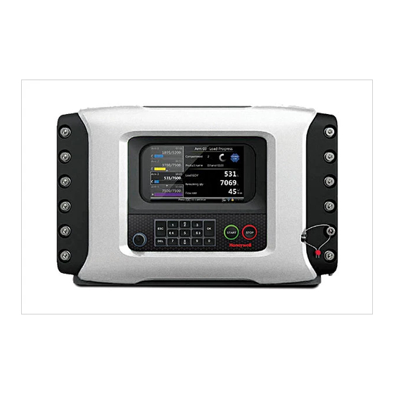
This manual is intended for service technicians, and bay operators (for example, truck drivers) who are assigned to install, commission, service, or operate the MSC-L. This Installation and Operations manual is aligned with Fusion4 MSC-L software version A2420. Part No.: 4418309_Rev09... - Page 18 General - Target Audience for this Manual FIGURE 1-2 Fusion4 Multi Stream Controller - Loading (MSC-L) Fusion4 MSC-L Part No.: 4418309_Rev09 Honeywell 1 - 4 Installation & Operation Manual...
-
Page 19: Chapter 2 Safety
The following caution symbol used in the manual recommends your attention to prevent damages to the equipment. Symbol Description General caution sign ElectroStatic Discharge (ESD) sensitive device Part No.: 4418309_Rev09 Fusion4 MSC-L Honeywell Installation & Operation Manual 2 - 1... -
Page 20: Safety Instructions For The Msc-L
MSC-L for EC declarations. 2.2.1.2 Control Drawings for FM & CSA Refer to the control drawings shipped with the MSC-L for the FM and CSA certifications. Fusion4 MSC-L Part No.: 4418309_Rev09 Honeywell 2- 2 Installation & Operation Manual... -
Page 21: Users
2.2.1.4 Additional Information For additional information about Honeywell Enraf’s solutions, see the back cover of this manual to contact Honeywell Enraf or its representative. 2.2.1.5 Environmental Conditions The environmental conditions regarding the permissible operating temperature for the MSC-L is -40 °C to +65 °C (-40 °F to +149 °F). -
Page 22: General
2. The bolts of the enclosure lid are captive (property class A2-70). Contact Honeywell Enraf if you need to replace the bolts. 3. Before closing the lid, check that all grounding connections including the grounding connection to the lid, are properly connected. - Page 23 Internal grounding connections of the MSC-L WARNING! Maintaining the ground bonding of the lid to the local Protective Earth (PE) using the lid ground wire is crucial for ensuring intrinsic safety. Part No.: 4418309_Rev09 Fusion4 MSC-L Honeywell Installation & Operation Manual 2 - 5...
-
Page 24: Accordance To Regulations
Ex d [ia] IIB T6 Gb 2.2.7.3 Low-Voltage Directive The MSC-L is suitable for the following categories. Pollution degree 2 Overvoltage category II Class I equipment Fusion4 MSC-L Part No.: 4418309_Rev09 Honeywell 2- 6 Installation & Operation Manual... -
Page 25: The Msc-L Labels
Safety - Safety Instructions for the MSC-L 2.2.7.4 The MSC-L Labels NOTE: Type plates are exemplary and subject to change. FIGURE 2-3 Identification labels with the safety note on the MSC-L Part No.: 4418309_Rev09 Fusion4 MSC-L Honeywell Installation & Operation Manual 2 - 7... -
Page 26: Safety Instructions For The Lad
WARNING! You must strictly follow all the safety instructions mentioned in this manual and the safety instructions shipped with the MSC-L during installation, commis- sioning, operation, and maintenance for the safe operation of the device. Fusion4 MSC-L Part No.: 4418309_Rev09 Honeywell 2- 8 Installation & Operation Manual... - Page 27 Division 2 Substitution of Division 2 Substitution of components components may impair resp. may impair intrinsic safety. intrinsic Zone 2 safety. Safe Safe Safe Area Zone Zone Part No.: 4418309_Rev09 Fusion4 MSC-L Honeywell Installation & Operation Manual 2 - 9...
-
Page 28: General
2.3.3 Commissioning The LAD and the Fusion4 parent devices must be commissioned using this controller trained by Honeywell Enraf. The service technician must have knowledge of the national, local and company requirements for electrical equipment in hazardous areas. -
Page 29: Additional Information
Safety - Safety Instructions for the LAD 2.3.6 Additional Information For additional information about Honeywell Enraf’s solutions, see the back cover of this manual to contact Honeywell Enraf or its representative. 2.3.7 Environmental Conditions The environmental conditions regarding the allowable operating temperature is -20 °C to +65 °C (-4 °F to +149 °F), relative humidity is... -
Page 30: The Lad Labels
Safety - Safety Instructions for the LAD 2.3.8 The LAD Labels NOTE to FM label: Ta = -4°F to +149ºF FIGURE 2-6 Identification labels with safety note on the LAD Fusion4 MSC-L Part No.: 4418309_Rev09 Honeywell 2- 12 Installation & Operation Manual... -
Page 31: Safety Instructions For The Ir Controller
Use only hazardous area. Use only approved area. Use only approved batteries, see approved batteries, see label. batteries, see label. label. Part No.: 4418309_Rev09 Fusion4 MSC-L Honeywell Installation & Operation Manual 2 - 13... -
Page 32: General
To prevent damage caused by leaking batteries, remove the batteries before storing the device in an unused condition for a long time. Fusion4 MSC-L Part No.: 4418309_Rev09 Honeywell 2- 14 Installation & Operation Manual... -
Page 33: Ec Declaration Of Conformity (For Eu)
2.4.6 Maintenance and Troubleshooting In the unlikely event of a malfunction, only a qualified service technician, trained by Honeywell Enraf, and with the knowledge of safety regulations for working in hazardous areas, must be allowed to repair the MSC-L. -
Page 34: Additional Information
Safety - Safety Instructions for the IR Controller 2.4.7 Additional Information For additional information about Honeywell Enraf’s solutions, see the back cover of this manual to contact Honeywell Enraf or its representative. 2.4.8 IR Controller Labels Fusion4 MSC-L Part No.: 4418309_Rev09... -
Page 35: Liability
electricity. The contents, descriptions, and specifications in this manual are subject to change without notice. Honeywell International Inc. accepts no responsibility for any errors that may appear in this manual. WARNING! Only certified technicians are authorized to make changes to the MSC-L configuration. All modifi- cations must be in accordance with the guidelines as set forth by Honeywell International Inc. - Page 36 Safety - Liability This page is intentionally left blank. Fusion4 MSC-L Part No.: 4418309_Rev09 Honeywell 2- 18 Installation & Operation Manual...
-
Page 37: Chapter 3 System Description
That is, each compartment has its own independent operation. If there are more than one load arm associated with the MSC-L then multiple batches may be running simultaneously in the MSC-L. Part No.: 4418309_Rev09 Fusion4 MSC-L Honeywell Installation & Operation Manual 3 - 1... -
Page 38: Batch Flow Stages
NOTE: To adequately match various specific applications, the MSC-L has a number of configurable parameters. For an explanation of all these parameters and their specific settings, see chapter 5 "Operation". Fusion4 MSC-L Part No.: 4418309_Rev09 Honeywell 3- 2 Installation & Operation Manual... -
Page 39: Types Of Blending
The blend product must have its own valve and meter. The combined, final, blended product must also have its own valve and meter. Part No.: 4418309_Rev09 Fusion4 MSC-L Honeywell Installation & Operation Manual 3 - 3... -
Page 40: Sequential Blending
The amount of each product and order of loading is defined by the recipe selected for the batch. See chapter 5 "Operation" for more details. FIGURE 3-4 Sequential Blending Piping Fusion4 MSC-L Part No.: 4418309_Rev09 Honeywell 3- 4 Installation & Operation Manual... -
Page 41: Additive Injection
The loading arm of the MSC-L supports the control of the following as described in the following figure. Maximum 7 product streams Maximum 12 additive streams (inclusive of internal additive streams and upto 6 external additive streams) Part No.: 4418309_Rev09 Fusion4 MSC-L Honeywell Installation & Operation Manual 3 - 5... - Page 42 Maximum 3 blend streams Maximum 6 additive streams (inclusive of internal and external additives) This sub set is defined by the recipes running on that arm. Fusion4 MSC-L Part No.: 4418309_Rev09 Honeywell 3- 6 Installation & Operation Manual...
-
Page 43: Device Loading Capabilities
A batch simultaneous controls a maximum of 10 streams: • Stream with main product • Up to 3 blend streams • Up to 6 additive streams Part No.: 4418309_Rev09 Fusion4 MSC-L Honeywell Installation & Operation Manual 3 - 7... -
Page 44: Menu-Based Msc-L Control
005) compared to previous national legislation, is that the total metering system is now subject to perform in the accuracy specification, and not just specific components. This means that not only the flow meter is subject to certification but also others. Fusion4 MSC-L Part No.: 4418309_Rev09 Honeywell 3- 8... -
Page 45: Component-Level Requirements
Therefore, ± 0.5% is the maximum allowed discrepancy between what the seller states as the volume transferred, and the actual volume the buyer receives. Part No.: 4418309_Rev09 Fusion4 MSC-L Honeywell Installation & Operation Manual 3 - 9... - Page 46 ASTM standards. If a temperature transmitter is applied, then component level requirements must also have an evaluation certificate. For the temperature sensor (Pt100) it is not required. Fusion4 MSC-L Part No.: 4418309_Rev09 Honeywell 3- 10 Installation & Operation Manual...
- Page 47 A very stringent requirement is the EMC standard for industrial use of electronic equipment. Electro-magnetic noise might influence the measurement of the metering signal, and this is not allowed to occur outside the maximum given accuracy. Part No.: 4418309_Rev09 Fusion4 MSC-L Honeywell Installation & Operation Manual 3 - 11...
-
Page 48: System-Level Requirements
MID and associated legislation such as OIML R117 and WELMEC. 3.2.5 The Fusion4 MSC-L The heart of the system is the Fusion4 MSC-L. Founded on Honeywell Enraf’s proprietary FlexConn™ architecture, the MSC-L is part of the Fusion4 portfolio of loading automation and control products family. -
Page 49: System Architecture
LAD interaction tools. 3.3 System Architecture The MSC-L is installed as per the Honeywell Enraf’s proprietary FlexConn architecture. The MSC-L is a member of Fusion4 portfolio of Loading Automation and Control products. - Page 50 FlexConn module. These modules communicate with each other through the serial CAN-bus. See FIGURE 3-7, for more information. F4 A1 0-00 04 FIGURE 3-7 The Fusion4 MSC-L architecture overview Fusion4 MSC-L Part No.: 4418309_Rev09 Honeywell 3- 14...
-
Page 51: Flexconn Modules
DCS, SCADA, tank inventory, or another terminal automation system. A display function - Ensures communication with the module(s) through an HMI. Part No.: 4418309_Rev09 Fusion4 MSC-L Honeywell Installation & Operation Manual 3 - 15... -
Page 52: Hardware Structure
32 captured bolts. See FIGURE 3-8, for more information. NOTE: Turn the bolts two times on the cosmetic cover to loosen the bolts and retain them in the lid. FIGURE 3-9 The MSC-L enclosure Fusion4 MSC-L Part No.: 4418309_Rev09 Honeywell 3- 16 Installation & Operation Manual... - Page 53 (see figure left) O-ring (standard available part) Glass Glass retainer rings (not visible in the front view of the MSC-L) Keyboard W&M switch Part No.: 4418309_Rev09 Fusion4 MSC-L Honeywell Installation & Operation Manual 3 - 17...
-
Page 54: Interior
The following boards can be placed in the MSC-L. MSC-SHORTCUT-BOARD ARM1-BACKPLANE-MSC ARM2-BACKPLANE-MSC EX-IO-HMI-MSC-L CAN-PSF-MSC CAN-HMI-MSC CAN-ARM-MSC CAN-IN-OUT-MSC FIGURE 3-11 PCB configurations, MSC-SHORTCUT-BOARD, and the CAN-HMI-MSC Fusion4 MSC-L Part No.: 4418309_Rev09 Honeywell 3- 18 Installation & Operation Manual... -
Page 55: Grounding Concept
FIGURE 3-12. In addition, these boards connect the GND cables, which are connected to Part No.: 4418309_Rev09 Fusion4 MSC-L Honeywell Installation & Operation Manual 3 - 19... - Page 56 Mechanical grounding of CAN-ARM-MSC and CAN-IN-OUT-MSC boards The CAN-HMI-MSC board, which is mounted on the lid of the MSC-L enclosure, connects directly to the metal housing through the nine mounting screws, as displayed in FIGURE 3-13. Fusion4 MSC-L Part No.: 4418309_Rev09 Honeywell 3- 20...
- Page 57 4. Reinstall the original cable assembly. Do not replace it with random parts. NOTE: Complete replacement of the lid should only be done in the Honeywell Enraf factory and not at the site. Part No.: 4418309_Rev09 Fusion4 MSC-L Honeywell Installation &...
- Page 58 M4 studs at the bottom, using the gland entries, as displayed in FIGURE 3-15. FIGURE 3-15 PE ground connections for external cables Fusion4 MSC-L Part No.: 4418309_Rev09 Honeywell 3- 22 Installation & Operation Manual...
-
Page 59: Pcb Layout
Function LEDs - Indicates the module specific activities such as the data being transmitted or received. Voltage monitors and temperature sensors - Used for internal diag- nostics purposes. Part No.: 4418309_Rev09 Fusion4 MSC-L Honeywell Installation & Operation Manual 3 - 23... -
Page 60: Pcb Details
It can be configured for a 2-wire half-duplex or a 4- wire full-duplex RS-485 communication. ETHERNET The Ethernet communication block is used for allowing the FlexConn microprocessor to communicate with the external devices using an Ethernet-compliant physical layer. Fusion4 MSC-L Part No.: 4418309_Rev09 Honeywell 3- 24 Installation & Operation Manual... - Page 61 RS485 (2-wire (Ethernet RS485 (4-wire isolated) isolated) isolated) FlexConn generic ext RAM LE1 LE2 LE3 LE4 LE5 LE6 FIGURE 3-16 CAN-HMI-MSC functions (top) and physical layout (bottom) Part No.: 4418309_Rev09 Fusion4 MSC-L Honeywell Installation & Operation Manual 3 - 25...
-
Page 62: Component Locations
Health of the board. Configurable. Configurable. Ethernet auto negotiation. Ethernet speed indicator. FPGA Health. U8,U9,U10 SDRAM. FPGA. ARM controller. Flash memory. A holder for IR receiver. Ambient light sensor. Fusion4 MSC-L Part No.: 4418309_Rev09 Honeywell 3- 26 Installation & Operation Manual... - Page 63 4 of COM PORT 5 When position (1-2) of jumper JP8 is closed, it will connect a resistance of 120 between terminals 1 & 2 of COM PORT 5 Part No.: 4418309_Rev09 Fusion4 MSC-L Honeywell Installation & Operation Manual 3 - 27...
-
Page 64: Can-Arm-Msc
Converts the temperature data from a remotely connected PT100 RTD 3-wire or 4-wire) circuits into a resistance value that can be read by the FlexConn microcontroller and then converted back into a temperature value. Fusion4 MSC-L Part No.: 4418309_Rev09 Honeywell 3- 28... - Page 65 (2-wire act/pass) passive) DO-SSR 3-wire or (AC) (DC) 4-wire COMMS Ethernet (2-wire isolated isolated) FlexConn generic ext RAM FIGURE 3-18 CAN-ARM-MSC functions (top) and physical layout (bottom) Part No.: 4418309_Rev09 Fusion4 MSC-L Honeywell Installation & Operation Manual 3 - 29...
-
Page 66: Component Locations
Connectors for interfacing with the ARM1-BACKPLANE-MSC or ARM2-BACKPLANE-MSC. Programming connector for U56 (ARM controller). Programming connector for U46 (PI processor -Cortex M0). 2-wire RS-485 communication interface 2-wire RS-485 communication interface Fusion4 MSC-L Part No.: 4418309_Rev09 Honeywell 3- 30 Installation & Operation Manual... -
Page 67: Can-In-Out-Msc
AC signals. 4 Digital Output Solid State Relay AC/DC Converts logic signals from the FlexConn generic microcontroller to (DO-SSR) circuits switched high power AC or DC signals. Part No.: 4418309_Rev09 Fusion4 MSC-L Honeywell Installation & Operation Manual 3 - 31... - Page 68 System Description - PCB Layout DI DC DI AC DO-SSR DO EMR (2-wire (AC) (AC+DC) passive) Watchdog FlexConn generic ext RAM FIGURE 3-20 CAN-IN-OUT-MSC functions (top) and physical layout (bottom) Fusion4 MSC-L Part No.: 4418309_Rev09 Honeywell 3- 32 Installation & Operation Manual...
-
Page 69: Component Locations
CN1, CN2 Connectors for interfacing with the ARM1-BACKPLANE-MSC or the ARM2-BACKPLANE-MSC. Health of the board. Configurable. Configurable. Cortex M4 CPU. K1-K10 Electro Mechanical Relay. K11-K14 Solid State Relay. Part No.: 4418309_Rev09 Fusion4 MSC-L Honeywell Installation & Operation Manual 3 - 33... -
Page 70: Can-Psf-Msc
The two PSUs make the system powering redundant. One PSU is able to power the complete system at maximum temperature. See FIGURE 3-22 for the functions of the MSC-L. FIGURE 3-22 CAN-PSF-MSC functions Fusion4 MSC-L Part No.: 4418309_Rev09 Honeywell 3- 34 Installation & Operation Manual... -
Page 71: Power Board Connection
Item Conditions Minimum Typical Maximum Unit Input voltage Input frequency Inrush current 230 V 37.3 Power Factor 115 V (at the maximum 230 V current) Power consumption Part No.: 4418309_Rev09 Fusion4 MSC-L Honeywell Installation & Operation Manual 3 - 35... - Page 72 DC Outputs (all) outputs The CAN-PSF-MSC board contains a 48 pin (DIN41612 F-type) press- fit connector. The signals are grouped as high voltage AC signals and low voltage DC signals. Fusion4 MSC-L Part No.: 4418309_Rev09 Honeywell 3- 36 Installation & Operation Manual...
-
Page 73: Fuse Boards
3.6.4 System Full-color (16 bits) WVGA, 8” diagonal display. Multi-language support for main screens which are as follows: • English US • English UK • French Part No.: 4418309_Rev09 Fusion4 MSC-L Honeywell Installation & Operation Manual 3 - 37... -
Page 74: Environment
Single Pulse Input / DI DC Input 3.8.2 and 3.8.3 Dual Pulse Input (Quad PI) 3.8.4 Analog Input (4-20mA Active/Passive) 3.8.5 Resistance Temperature Detector- 3.8.6 RTD Temperature Input (3-wire or 4- wire) Fusion4 MSC-L Part No.: 4418309_Rev09 Honeywell 3- 38 Installation & Operation Manual... - Page 75 Digital Output AC (Solid state relay) 3.9.6 RS-485 Communication (2-wire) 3.10.2 RS-485 Communication (4-wire) 3.10.2 Ethernet Communication 3.10.3 For the configuration of these I/O functions, see chapter 5 "Operation". Part No.: 4418309_Rev09 Fusion4 MSC-L Honeywell Installation & Operation Manual 3 - 39...
-
Page 76: Input Functions
DC into a signal that can be used by the controller to ensure specific functionality required. Two types of contacts are available which are as follows: 1. External DC voltage switching 2. Volt free switching Fusion4 MSC-L Part No.: 4418309_Rev09 Honeywell 3- 40 Installation & Operation Manual... - Page 77 COMMON Voltage free contact External equipment CAN-ARM-MSC or CAN-IN-OUT-MSC DCx_hi COMMON NPN open collector-emitter (Load computer, PLC, TAS, or external switching voltage) FIGURE 3-25 DI DC connections Part No.: 4418309_Rev09 Fusion4 MSC-L Honeywell Installation & Operation Manual 3 - 41...
-
Page 78: Characteristics
3.8.3.1 Functional Description The function of the Single Pulse Input is to accept pulse signals from a product stream single pulse flowmeter or an additive stream single pulse flowmeter. Fusion4 MSC-L Part No.: 4418309_Rev09 Honeywell 3- 42 Installation & Operation Manual... - Page 79 Single Pulse Input connections NOTE: The connector CN135 used in the illustration refers to the connector on the backplane that connects to QPI1. This is only an example. Part No.: 4418309_Rev09 Fusion4 MSC-L Honeywell Installation & Operation Manual 3 - 43...
-
Page 80: Characteristics
NOTE: The dual-pulse input cannot be used for accepting signals from two separate single-pulse flow meters. FIGURE 3-27 illustrates the simplified block diagram of the Dual-Pulse Input connections. Fusion4 MSC-L Part No.: 4418309_Rev09 Honeywell 3- 44 Installation & Operation Manual... - Page 81 Dual-Pulse Input connections NOTE: The connector CN135 used in the illustration refers to the connector on the backplane that connects to QPI1. It is only an example. Part No.: 4418309_Rev09 Fusion4 MSC-L Honeywell Installation & Operation Manual 3 - 45...
-
Page 82: Characteristics
See FIGURE 3- In the active mode, the external transmitter is directly powered from the 24 V, which is generated by the MSC-L power supply. Fusion4 MSC-L Part No.: 4418309_Rev09 Honeywell 3- 46 Installation &... - Page 83 The AI interface is not intrinsically safe, and external devices connected to the AI must conform to Ex d safety standards when used in a hazardous area. Part No.: 4418309_Rev09 Fusion4 MSC-L Honeywell Installation & Operation Manual 3 - 47...
-
Page 84: Characteristics
The Resistance Temperature Detector (RTD) input allows the controller to read the temperature of a remotely connected PT100 resistance temperature detector. FIGURE 3-29 illustrates the RTD connections. The RTD input supports 3-wire connections and 4-wire connections. Fusion4 MSC-L Part No.: 4418309_Rev09 Honeywell 3- 48... - Page 85 PT100 RTD element IEC 60751(0.385Ω/ C) External equipment CAN-ARM-MSC CN141 RTD S- RTD COM 3-Wire RTD POS PT100 RTD element IEC 60751(0.385Ω/ C) FIGURE 3-29 RTD connections Part No.: 4418309_Rev09 Fusion4 MSC-L Honeywell Installation & Operation Manual 3 - 49...
-
Page 86: Characteristics
AC into a signal that can be used by the controller to ensure the specific functionality required. FIGURE 3-30 illustrates the simplified block diagram of the DI AC connections. Fusion4 MSC-L Part No.: 4418309_Rev09 Honeywell 3- 50 Installation & Operation Manual... -
Page 87: Characteristics
Input impedance k High input (must turn on) voltage Low input (must turn off) voltage Maximum input switching frequency AC on time (T AC off time (T Part No.: 4418309_Rev09 Fusion4 MSC-L Honeywell Installation & Operation Manual 3 - 51... -
Page 88: Output Functions
Factored PO circuitry is controlled by a micro controller to present a certain pulse input signal factored (scaled) to the pulse output channel. FIGURE 3-31 illustrates the simplified block diagram of the external PO connections. Fusion4 MSC-L Part No.: 4418309_Rev09 Honeywell 3- 52... - Page 89 DC PSU 2 or 4 (Pox_LO) LOAD CAN-ARM-MSC External equipment CN144 1 or 3 (Pox_HI) LOAD External DC PSU 2 or 4 (Pox_LO) FIGURE 3-31 PO connections Part No.: 4418309_Rev09 Fusion4 MSC-L Honeywell Installation & Operation Manual 3 - 53...
-
Page 90: Characteristics
External equipment CAN-ARM-MSC or CAN-IN-OUT-MSC 1, 3 or 5 (AO_ax) External DC power supply 4-20mA 2, 4 or 6 (AO_bx) FIGURE 3-32 AO connections Fusion4 MSC-L Part No.: 4418309_Rev09 Honeywell 3- 54 Installation & Operation Manual... - Page 91 Open (NO) or Normally Closed (NC). FIGURE 3-33 illustrates the simplified block diagram of the DO EMR DC connections. 1. For physical location(s), see CHAPTER 4 - Installation. Part No.: 4418309_Rev09 Fusion4 MSC-L Honeywell Installation & Operation Manual 3 - 55...
- Page 92 Switching current Steady state current Output contact type SPST Operate time Release time Setting time Control voltage (high level) Control voltage (low level) Control current (high level) Fusion4 MSC-L Part No.: 4418309_Rev09 Honeywell 3- 56 Installation & Operation Manual...
- Page 93 Open (NO) or Normally Closed (NC). See FIGURE 3-34 illustrates the simplified block diagram of the DO EMR connections. 1. For physical location(s), see CHAPTER 4 - Installation. Part No.: 4418309_Rev09 Fusion4 MSC-L Honeywell Installation & Operation Manual 3 - 57...
- Page 94 Configurable as N/O or N/C via jumper CAN-IN-OUT-MSC External equipment 1,3,5,7 [EMRx_no] 3A(T) 2,4,6,8 [EMR_common] LOAD SPST Configurable as N/O or N/C via jumper FIGURE 3-34 DO EMR connections Fusion4 MSC-L Part No.: 4418309_Rev09 Honeywell 3- 58 Installation & Operation Manual...
-
Page 95: Characteristics
FIGURE 3-35 illustrates a simplified block diagram of the DO-SSR AC self powered connections and FIGURE 3-36 illustrates a simplified block diagram of the DO-SSR AC externally powered connections. Part No.: 4418309_Rev09 Fusion4 MSC-L Honeywell Installation & Operation Manual 3 - 59... - Page 96 AC Mains supply Fuse 1.5A(T) CAN-ARM-MSC or CAN-IN-OUT-MSC SSrx_feed_ac SSrx_sw_ac LOAD Solid State Relay Typical load is an additive solenoid or blend DVC FIGURE 3-35 Solid State Relay “Self-powered” connections Fusion4 MSC-L Part No.: 4418309_Rev09 Honeywell 3- 60 Installation & Operation Manual...
-
Page 97: Characteristics
Output surge load current Off state output leakage current Off state output blocking voltage Switching time Control voltage must turn Control voltage must turn Control current Part No.: 4418309_Rev09 Fusion4 MSC-L Honeywell Installation & Operation Manual 3 - 61... -
Page 98: Communication Functions
TAS system, Fusion4 Portal, or other remote interfaces. For the CAN-HMI-MSC, CH5 can be configured for either a 2-wire half- duplex or a 4-wire full-duplex. Fusion4 MSC-L Part No.: 4418309_Rev09 Honeywell 3- 62 Installation & Operation Manual... - Page 99 CAN-HMI-MSC External equipment CN151 RS485_A_CH5 RS485_B_CH5 RS485_Y_CH5 RS485_Z_CH5 RS485_Common_CH5 RS-485 TRANSCEIVER 0V connection is omitted for some RS-485 applications FIGURE 3-38 RS Communication 4-wire connections (CAN-HMI-MSC only) Part No.: 4418309_Rev09 Fusion4 MSC-L Honeywell Installation & Operation Manual 3 - 63...
-
Page 100: Characteristics
The function of the Ethernet Communication (ETHERNET) block is to allow the FlexConn microprocessor to communicate through an Ethernet compliant physical layer with external devices including a TAS system, Fusion4 Portal, or other remote interfaces. Fusion4 MSC-L Part No.: 4418309_Rev09 Honeywell 3- 64... -
Page 101: Characteristics
Data transmission rate mbps 3.10.3.3 Cable Specifications Item Minimum Typical Maximum Unit Cable length Cable characteristic impedance Cable DC loop resistance ≤ 0.188 m Cable capacitance pF/m Part No.: 4418309_Rev09 Fusion4 MSC-L Honeywell Installation & Operation Manual 3 - 65... -
Page 102: Security Guidelines
System Description - Security Guidelines 3.11 Security Guidelines This section provides security guidelines for Fusion4 MSC-L/MSC-A. 3.11.1 Device Security Recommendations Following are recommendations to prevent malicious users from accessing the device and its data Change the default password on first use and ensure that the user ... - Page 103 Honeywell products and services. To report a potential security vulnerability against any Honeywell product, please follow the instructions at: https://honeywell.com/pages/vulnerabilityreporting.aspx Submit the requested information to Honeywell using one of the following methods: [email protected] Send an email to ...
- Page 104 System Description - Security Guidelines This page is intentionally left blank. Fusion4 MSC-L Part No.: 4418309_Rev09 Honeywell 3- 68 Installation & Operation Manual...
-
Page 105: Chapter 4 Installation
Thread: M10x1.5 g6 Type: ISO 4762 Material: A2 70 Torque: 33 Nm [22.12 lb-ft - 25.077 lb-ft] 2. An Ex flame path by means of an internal flange. Part No.: 4418309_Rev09 Fusion4 MSC-L Honeywell Installation & Operation Manual 4 - 1... - Page 106 4. An O-ring positioned inside the lid, as illustrated in the following figure. 5. Wall mounting facilities - There are four wall mounting bolts, as illus- trated in the following figure. The size of the bolts is M10*1.5 - g6. Fusion4 MSC-L Part No.: 4418309_Rev09 Honeywell 4 - 2...
- Page 107 6. Base mounting facilities - The base mounting holes are located on the right side and the left side of the MSC-L, as illustrated in the following figure. NOTE: The base mounting bolt thread size is M10. Part No.: 4418309_Rev09 Fusion4 MSC-L Honeywell Installation & Operation Manual 4 - 3...
- Page 108 See for more information. 10. Metric or the NPT cable entry layout. See section 4.2 - Gland Entries, for more information. Fusion4 MSC-L Part No.: 4418309_Rev09 Honeywell 4 - 4 Installation & Operation Manual...
- Page 109 WARNING! Do not drill into the housing as this invalidates the explosion safety approvals. REMARK: Refer to the specific equipment’s guides for directions to carry and lift the equipment or parts that weigh more than 18 kgs. Part No.: 4418309_Rev09 Fusion4 MSC-L Honeywell Installation & Operation Manual 4 - 5...
-
Page 110: Gland Entries
6 x M40 6 x M32 (auxiliary) 1 x non-metric (½” NPT) not for wiring, but for optional breather. FIGURE 4-2 Metric gland entries overview Fusion4 MSC-L Part No.: 4418309_Rev09 Honeywell 4 - 6 Installation & Operation Manual... -
Page 111: Npt Cable Entries
The MSC-L with an optional NPT cable entry layout, supports the following thread sizes. 4 x 1½'' NPT 4 x ¾'' NPT 1 x ½'' NPT (optional breather) FIGURE 4-3 NPT cable entries overview Part No.: 4418309_Rev09 Fusion4 MSC-L Honeywell Installation & Operation Manual 4 - 7... -
Page 112: Opening The Msc-L
3. Loosen all the 32 bolts by loosening one or two threads of the bolts with an 8 mm Allen key. The MSC-L lid can now be opened. 8 mm Fusion4 MSC-L Part No.: 4418309_Rev09 Honeywell 4 - 8 Installation & Operation Manual... - Page 113 5. Remove the screw of the earth strap protection cable on the MSC-L lid. Part No.: 4418309_Rev09 Fusion4 MSC-L Honeywell Installation & Operation Manual 4 - 9...
- Page 114 Installation - Opening the MSC-L 6. Remove the screw on the earth strap assembly from the MSC-L lid. NOTE: The screw must be removed only by Honeywell Enraf trained service technicians. 7. Remove the screws that hold the boards fastened to the enclosure with a 4 mm allen key.
-
Page 115: Closing The Msc Lid
2. Remove the 2x cable (grounding cable and cable to prevent over- stretching door after oppening the door) before replacing the O-ring. NOTE: The O-ring must be replaced only by the Honeywell service technician Enraf trained by 3. -
Page 116: Removing/Replacing The Pcbs
1. Remove the MSC-SHORTCUT-BOARD from the backplanes by pulling the MSC-L fuse board cover. MSC-SHORTCUT-BOARD NOTE: To replace the perform the previous steps in reverse order. NOTE: Do not remove the CAN-PSF-MSC board. Fusion4 MSC-L Part No.: 4418309_Rev09 Honeywell 4 - 12 Installation & Operation Manual... -
Page 117: Fusing And Power Consumption
MSC-L is also routed to the external devices through the MSC- SHORTCUT-BOARD. The fuses on the MSC fuse board deliver fuse protected AC power to the external devices. Part No.: 4418309_Rev09 Fusion4 MSC-L Honeywell Installation & Operation Manual... - Page 118 4 pin connector for field connection 48 pin connector for CAN-ARM or 4 pin connector for Shortcut board CAN-IN-OUT board FIGURE 4-4 Block schematic of a zero ohm resistor on the MSC-SHORTCUT-BOARD Fusion4 MSC-L Part No.: 4418309_Rev09 Honeywell 4 - 14 Installation & Operation Manual...
- Page 119 1 A with l t < 1.6 AC_FUSED_1 AC_FUSED_2 AC_FUSED_3 AC_FUSED_4 AC_FUSED_5 AC_FUSED_6 10 A with 1500 breaking current AC_FUSED_7 AC_FUSED_8 AC_FUSED_9 AC_FUSED_10 FIGURE 4-5 Architecture of MSC-SHORTCUT-BOARD Part No.: 4418309_Rev09 Fusion4 MSC-L Honeywell Installation & Operation Manual 4 - 15...
-
Page 120: External Fusing
The dissipation is based on the maximum load. CAN-IN-OUT- 25 W The dissipation is based on the maximum load. CAN-HMI-MSC 7.2 W The dissipation is based on the maximum load. Fusion4 MSC-L Part No.: 4418309_Rev09 Honeywell 4 - 16 Installation & Operation Manual... -
Page 121: Disconnecting/Breaker Device
20 A fuse shall be incorporated external to the equipment. 4.7 Wiring Termination Guidance 4.7.1 Wiring Architecture Ex i wiring is separated from other wiring. Part No.: 4418309_Rev09 Fusion4 MSC-L Honeywell Installation & Operation Manual 4 - 17... - Page 122 To limit the interference between low voltage and high voltage signals, a logical separation between cables containing the signals are created. FIGURE 4-6 High/low voltages separation concept Fusion4 MSC-L Part No.: 4418309_Rev09 Honeywell 4 - 18 Installation & Operation Manual...
-
Page 123: Backplane Boards
The connectors contain 3, 4, 5, 6, or 8 pins. ARM-1- Backplane-MSC start with the CN number CN101 and contains 52 connectors. ARM-2-Backplane-MSC start with the CN number CN201 and contains 49 connectors. FIGURE 4-7 Backplane boards Part No.: 4418309_Rev09 Fusion4 MSC-L Honeywell Installation & Operation Manual 4 - 19... - Page 124 Installation - Wiring Termination Guidance 4.7.2.1 ARM-1-BACKPLANE-MSC FIGURE 4-8 ARM-1-BACKPLANE-MSC Fusion4 MSC-L Part No.: 4418309_Rev09 Honeywell 4 - 20 Installation & Operation Manual...
- Page 125 HI LO HI LO DO-SSR COM-5 ETH-1 ETH-2 AI-7 CN115 CN151 CN147 CN152 CN134 F O N L F O N L FIGURE 4-9 Blackplane arrangement of ARM-1-BACKPLANE-MSC Part No.: 4418309_Rev09 Fusion4 MSC-L Honeywell Installation & Operation Manual 4 - 21...
- Page 126 DO-EMR-AC-DC CAN-IN-OUT-MSC-2 DO-EMR- DO-EMR-AC-DC CAN-IN-OUT-MSC-2 DO-EMR- CN-106 DO-SSR-AC CAN-ARM-MSC-1 Orange DO-SSR-1 DO-SSR-AC CAN-ARM-MSC-1 DO-SSR-2 CN-107 DO-SSR-AC CAN-ARM-MSC-1 Orange DO-SSR-3 DO-SSR-AC CAN-ARM-MSC-1 DO-SSR-4 CN-108 DO-SSR-AC CAN-ARM-MSC-1 Orange DO-SSR-5 Fusion4 MSC-L Part No.: 4418309_Rev09 Honeywell 4 - 22 Installation & Operation Manual...
- Page 127 CAN-IN-OUT-MSC-2 DO-SSR- CN-115 DO-SSR-AC CAN-IN-OUT-MSC-2 Orange DO-SSR- DO-SSR-AC CAN-IN-OUT-MSC-2 DO-SSR- CN-116 DI-AC CAN-IN-OUT-MSC-1 DI-AC-1 DI-AC CAN-IN-OUT-MSC-1 DI-AC-2 DI-AC CAN-IN-OUT-MSC-1 DI-AC-3 CN-117 DI-AC CAN-IN-OUT-MSC-2 DI-AC-4 DI-AC CAN-IN-OUT-MSC-2 DI-AC-5 Part No.: 4418309_Rev09 Fusion4 MSC-L Honeywell Installation & Operation Manual 4 - 23...
- Page 128 CAN-IN-OUT-MSC-2 DI-DC-29 DI-DC CAN-IN-OUT-MSC-2 DI-DC-30 Green CN-128 CAN-ARM-MSC-1 U-11 AI-1 CN-129 CAN-ARM-MSC-1 Green U-10 AI-2 CN-130 CAN-ARM-MSC-1 Green AI-3 CN-131 CAN-ARM-MSC-1 Green AI-4 CN-132 CAN-ARM-MSC-1 Green AI-5 Fusion4 MSC-L Part No.: 4418309_Rev09 Honeywell 4 - 24 Installation & Operation Manual...
- Page 129 COMMS CAN-HMI-MSC COM-5 CN-152 ETHER CAN-HMI-MSC Black ETH-2 TYPE FUNCTION BOARD NAME CN-160 subD15 HMI-LINK-1 CAN-HMI-MSC CN-160 CN-161 subD15 HMI-LINK-2 CAN-HMI-MSC CN-161 CN-162 subD25 BACKPLANE-LINK ARM-2-BACKPLANE-MSC CN-162 Part No.: 4418309_Rev09 Fusion4 MSC-L Honeywell Installation & Operation Manual 4 - 25...
- Page 130 CAN-ARM-MSC-1 CN-165 CN-166 IN-OUT-BOARD CAN-IN-OUT-MSC-1 CN-166 CN-167 IN-OUT-BOARD CAN-IN-OUT-MSC-1 CN-167 CN-168 IN-OUT-BOARD CAN-IN-OUT-MSC-2 CN-168 CN-169 IN-OUT-BOARD CAN-IN-OUT-MSC-2 CN-169 CN-170 FUSE-BOARD MSC-SHORTCUT-BOARD-1 CN-170 4.7.2.4 ARM-2-BACKPLANE-MSC FIGURE 4-10 ARM-2-BACKPLANE-MSC Fusion4 MSC-L Part No.: 4418309_Rev09 Honeywell 4 - 26 Installation & Operation Manual...
- Page 131 CN249 F O N F O N HI LO HI LO ETH-3 DO-SSR CN247 CN215 F O N F O N FIGURE 4-11 Blackplane arrangement of ARM-2-BACKPLANE-MSC Part No.: 4418309_Rev09 Fusion4 MSC-L Honeywell Installation & Operation Manual 4 - 27...
- Page 132 CAN-ARM-MSC-2 Orange DO-SSR-23 DO-SSR-AC CAN-ARM-MSC-2 DO-SSR-24 CN-208 DO-SSR-AC CAN-ARM-MSC-2 Orange DO-SSR-25 DO-SSR-AC CAN-ARM-MSC-2 DO-SSR-26 CN-209 DO-SSR-AC CAN-ARM-MSC-2 Orange DO-SSR-27 DO-SSR-AC CAN-ARM-MSC-2 DO-SSR-28 Orange CN-210 DO-SSR-AC CAN-ARM-MSC-2 DO-SSR-29 Fusion4 MSC-L Part No.: 4418309_Rev09 Honeywell 4 - 28 Installation & Operation Manual...
- Page 133 CN-220 DI-DC CAN-IN-OUT-MSC-3 Green DI-DC-37 DI-DC CAN-IN-OUT-MSC-3 DI-DC-38 DI-DC CAN-IN-OUT-MSC-3 DI-DC-39 CN-221 DI-DC CAN-IN-OUT-MSC-3 Green DI-DC-40 DI-DC CAN-IN-OUT-MSC-3 DI-DC-41 DI-DC CAN-IN-OUT-MSC-3 DI-DC-42 Green CN-222 DI-DC CAN-IN-OUT-MSC-3 DI-DC-43 Part No.: 4418309_Rev09 Fusion4 MSC-L Honeywell Installation & Operation Manual 4 - 29...
- Page 134 QPI-B CAN-ARM-MSC-2 QPI-9B CN-238 QPI-A CAN-ARM-MSC-2 Green QPI-10A QPI-B CAN-ARM-MSC-2 QPI-10B CN-239 QPI-A CAN-ARM-MSC-2 Green QPI-11A QPI-B CAN-ARM-MSC-2 QPI-11B CN-240 QPI-A CAN-ARM-MSC-2 Green QPI-12A QPI-B CAN-ARM-MSC-2 QPI-12B Fusion4 MSC-L Part No.: 4418309_Rev09 Honeywell 4 - 30 Installation & Operation Manual...
- Page 135 • For color codes of connectors, see the following table. Color Function High voltage input signals Orange High voltage output signals Part No.: 4418309_Rev09 Fusion4 MSC-L Honeywell Installation & Operation Manual 4 - 31...
- Page 136 All primary wiring needs to be provided with insulation rated for minimum 300 V, with a rated temperature of at least 105 °C [221 °F] and with a conductor size of at least 0.75 mm [AWG 18]. Fusion4 MSC-L Part No.: 4418309_Rev09 Honeywell 4 - 32...
- Page 137 NOTE: Wire crimps are to reinforce the fine wire strands when terminating a cable into a connector block. Wire crimps are not required to be fitted for solid-core cable wires. Part No.: 4418309_Rev09 Fusion4 MSC-L Honeywell Installation & Operation Manual...
- Page 138 Installation - Wiring Termination Guidance 4.7.6 Internal Wiring diagram 4.7.6.1 AC Cable 1 (Gland 1) FIGURE 4-12 AC cable 1 (gland 1) Fusion4 MSC-L Part No.: 4418309_Rev09 Honeywell 4 - 34 Installation & Operation Manual...
- Page 139 Installation - Wiring Termination Guidance 4.7.6.2 AC Cable 2 (Gland 2) FIGURE 4-13 AC cable 2 (gland 2) 4.7.6.3 DC cable 1 (Gland 3) FIGURE 4-14 DC cable 1 (gland 3) Part No.: 4418309_Rev09 Fusion4 MSC-L Honeywell Installation & Operation Manual 4 - 35...
- Page 140 Installation - Wiring Termination Guidance 4.7.6.4 AC Cable 3 (Gland 4) FIGURE 4-15 AC cable 3 (gland 4) 4.7.6.5 AC Cable 4 (Gland 5) FIGURE 4-16 AC cable 4 (gland 5) Fusion4 MSC-L Part No.: 4418309_Rev09 Honeywell 4 - 36 Installation & Operation Manual...
- Page 141 Installation - Wiring Termination Guidance 4.7.6.6 Analog Cable 1 (Gland 6) FIGURE 4-17 Analog cable 1 (gland 6) Part No.: 4418309_Rev09 Fusion4 MSC-L Honeywell Installation & Operation Manual 4 - 37...
- Page 142 Installation - Wiring Termination Guidance 4.7.6.7 AC Cable 5 (Gland 7) FIGURE 4-18 AC cable 5 (gland 7) 4.7.6.8 DC Cable 2 (Gland 8) FIGURE 4-19 DC cable 2 (gland 8) Fusion4 MSC-L Part No.: 4418309_Rev09 Honeywell 4 - 38 Installation & Operation Manual...
- Page 143 Installation - Wiring Termination Guidance 4.7.6.9 DC Cable 3 (Gland 9) FIGURE 4-20 DC cable 3 (gland 9) Part No.: 4418309_Rev09 Fusion4 MSC-L Honeywell Installation & Operation Manual 4 - 39...
- Page 144 Installation - Wiring Termination Guidance 4.7.6.10 DC Cable 4 (Gland 10) FIGURE 4-21 DC cable 4 (gland 10) 4.7.6.11 DC Cable 5 (Gland 11) FIGURE 4-22 DC cable 5 (gland 11) Fusion4 MSC-L Part No.: 4418309_Rev09 Honeywell 4 - 40 Installation & Operation Manual...
- Page 145 Installation - Wiring Termination Guidance 4.7.6.12 Comms Cable 1 (Gland 12) FIGURE 4-23 Comms cable 1 (gland 12) 4.7.6.13 DC Cable 6 (Gland 13) FIGURE 4-24 DC cable 6 (gland 13) Part No.: 4418309_Rev09 Fusion4 MSC-L Honeywell Installation & Operation Manual 4 - 41...
- Page 146 DC cable 7 (gland 14) 4.7.6.15 Comms Cable 2 (Gland 15) FIGURE 4-26 Comms cable 2 (gland 15) 4.7.6.16 DC Cable 8 (Gland 16) FIGURE 4-27 DC cable 8 (gland 16) Fusion4 MSC-L Part No.: 4418309_Rev09 Honeywell 4 - 42 Installation & Operation Manual...
- Page 147 DC cable 9 (gland 17) 4.7.6.18 AC Cable 6 (Gland 18) FIGURE 4-29 AC cable 6 (Gland 18) 4.7.6.19 DC Cable 10 (Gland 19) FIGURE 4-30 DC cable 10 (gland 19) Part No.: 4418309_Rev09 Fusion4 MSC-L Honeywell Installation & Operation Manual 4 - 43...
- Page 148 Installation - Wiring Termination Guidance 4.7.6.20 DC Cable 11 (Gland 20) FIGURE 4-31 DC cable 11 (gland 20) Fusion4 MSC-L Part No.: 4418309_Rev09 Honeywell 4 - 44 Installation & Operation Manual...
- Page 149 Installation - Wiring Termination Guidance 4.7.6.21 AC Cable 7 (Gland 21) FIGURE 4-32 AC cable 7 (gland 21) 4.7.6.22 AC Cable 8 (Gland 22) FIGURE 4-33 AC cable 8 (gland 22) Part No.: 4418309_Rev09 Fusion4 MSC-L Honeywell Installation & Operation Manual 4 - 45...
- Page 150 Installation - Wiring Termination Guidance 4.7.6.23 Analog Cable 2 (Gland 23) FIGURE 4-34 Analog cable 2 (gland 23) Fusion4 MSC-L Part No.: 4418309_Rev09 Honeywell 4 - 46 Installation & Operation Manual...
- Page 151 Installation - Wiring Termination Guidance 4.7.6.24 AC Cable 9 (Gland 24) FIGURE 4-35 AC cable 9 (gland 24) Part No.: 4418309_Rev09 Fusion4 MSC-L Honeywell Installation & Operation Manual 4 - 47...
- Page 152 Installation - Wiring Termination Guidance 4.7.6.25 AC Cable 10 (Gland 25) FIGURE 4-36 AC cable 10 (gland 25) Fusion4 MSC-L Part No.: 4418309_Rev09 Honeywell 4 - 48 Installation & Operation Manual...
- Page 153 4.7.8 ARM-1-BACKPLANE-MSC Terminal Assignment Guide The following table provides information for the basic function assignment to specific terminals. Majority of the MSC-L functions can be assigned to multiple I/O. Part No.: 4418309_Rev09 Fusion4 MSC-L Honeywell Installation & Operation Manual 4 - 49...
- Page 154 Contact for Actuator output External Additive solenoid Supply DO-EMR-3 EMR_common Contact for External load switching DO-EMR-4 EMR4_no Contact for External Supply DO-EMR-4 EMR_common Contact for External load switching Fusion4 MSC-L Part No.: 4418309_Rev09 Honeywell 4 - 50 Installation & Operation Manual...
- Page 155 DO-EMR-7 EMR7_no Contact for External Supply DO-EMR-7 EMR_common Contact for External load switching DO-EMR-8 EMR8_no Contact for External Supply DO-EMR-8 EMR_common Contact for External load switching CN-103 Part No.: 4418309_Rev09 Fusion4 MSC-L Honeywell Installation & Operation Manual 4 - 51...
- Page 156 DO-EMR-13 EMR13_no Contact for External Supply DO-EMR-13 EMR_common Contact for External load switching DO-EMR-14 EMR14_no Contact for External Supply DO-EMR-14 EMR_common Contact for External load switching CN-104 Fusion4 MSC-L Part No.: 4418309_Rev09 Honeywell 4 - 52 Installation & Operation Manual...
- Page 157 Additive solenoid DO-EMR-17 EMR17_no Contact for External Supply DO-EMR-17 EMR_common Contact for External load switching DO-EMR-18 EMR18_no Contact for External Supply DO-EMR-18 EMR_common Contact for External load switching Part No.: 4418309_Rev09 Fusion4 MSC-L Honeywell Installation & Operation Manual 4 - 53...
- Page 158 A/C Live DO-SSR-2 SSR2_feed Feed DO-SSR-2 SSR2_sw Signal - Output Alarm shutdown Alarm indication DO-SSR-2 Neutral Pump start DO-SSR-2 A/C Live Product block valve Additive blocking valve CN-107 Fusion4 MSC-L Part No.: 4418309_Rev09 Honeywell 4 - 54 Installation & Operation Manual...
- Page 159 A/C Live DO-SSR-4 SSR4_feed Feed DO-SSR-4 SSR4_sw Signal - Output Alarm shutdown Alarm indication DO-SSR-4 Neutral Pump start DO-SSR-4 A/C Live Product block valve Additive blocking valve Part No.: 4418309_Rev09 Fusion4 MSC-L Honeywell Installation & Operation Manual 4 - 55...
- Page 160 Neutral DO-SSR-7 Live DO-SSR-8 SSR8_feed_ac Feed DO-SSR-8 SSR8_sw_ac Signal - Output Alarm shutdown Alarm indication DO-SSR-8 Neutral Pump start DO-SSR-8 Live Product block valve Additive blocking valve Fusion4 MSC-L Part No.: 4418309_Rev09 Honeywell 4 - 56 Installation & Operation Manual...
- Page 161 Neutral DO-SSR-13 Live DO-SSR-14 SSR14_feed_a Feed Alarm shutdown Alarm indication DO-SSR-14 SSR14_sw_ac Signal - Output Pump start Product block DO-SSR-14 Neutral valve DO-SSR-14 Live Additive blocking valve Part No.: 4418309_Rev09 Fusion4 MSC-L Honeywell Installation & Operation Manual 4 - 57...
- Page 162 Neutral DO-SSR-17 Live DO-SSR-18 SSR18_feed_a Feed Alarm shutdown Alarm indication DO-SSR-18 SSR18_sw_ac Signal - Output Pump start Product block DO-SSR-18 Neutral valve DO-SSR-18 Live Additive blocking valve Fusion4 MSC-L Part No.: 4418309_Rev09 Honeywell 4 - 58 Installation & Operation Manual...
- Page 163 Signal - Input DC input control Programmable Inputs DI-DC-1 COMMON Common ESD input DI-DC-2 DC2_hi Signal - Input DI-DC-2 COMMON Common DI-DC-3 DC3_hi Signal - Input DI-DC-3 COMMON Common Part No.: 4418309_Rev09 Fusion4 MSC-L Honeywell Installation & Operation Manual 4 - 59...
- Page 164 Signal - Input DC input control Programmable Inputs DI-DC-13 COMMON Common ESD input DI-DC-14 DC14_hi Signal - Input DI-DC-14 COMMON Common DI-DC-15 DC15_hi Signal - Input DI-DC-15 COMMON Common Fusion4 MSC-L Part No.: 4418309_Rev09 Honeywell 4 - 60 Installation & Operation Manual...
- Page 165 Signal - Input DC input control Programmable Inputs DI-DC-25 COMMON Common ESD input DI-DC-26 DC26_hi Signal - Input DI-DC-26 COMMON Common DI-DC-27 DC27_hi Signal - Input DI-DC-27 COMMON Common Part No.: 4418309_Rev09 Fusion4 MSC-L Honeywell Installation & Operation Manual 4 - 61...
- Page 166 4-20 mA input for mode) control temperature measurement. AI-3 24 V common Common Digital mode for (passive "digital input". mode) AI-3 Analog signal Signal - Input (active + passive mode) Fusion4 MSC-L Part No.: 4418309_Rev09 Honeywell 4 - 62 Installation & Operation Manual...
- Page 167 4-20 mA input for mode) control temperature measurement. AI-7 24 V common Common Digital mode for (passive "digital input". mode) AI-7 Analog signal Signal - Input (active + passive mode) Part No.: 4418309_Rev09 Fusion4 MSC-L Honeywell Installation & Operation Manual 4 - 63...
- Page 168 PULSE A Pulse Signal - Input A QPI-3B 12 V 12 V DC Power METER POWER QPI-3B COMMON Common QPI-3B PULSE B Pulse Signal - Input B Fusion4 MSC-L Part No.: 4418309_Rev09 Honeywell 4 - 64 Installation & Operation Manual...
- Page 169 PULSE A Pulse Signal - Input A QPI-6B 12 V 12 V DC Power METER POWER QPI-6B COMMON Common QPI-6B PULSE B Pulse Signal - Input B Part No.: 4418309_Rev09 Fusion4 MSC-L Honeywell Installation & Operation Manual 4 - 65...
- Page 170 PO-1 Po1_LO Signal - Output pulse output. Additive injection PO-2 Po2_HI Feed feedback, Alarm PO-2 Po2_LO Signal - Output shutdown, Alarm indication, Pump start, Additive blocking valve Fusion4 MSC-L Part No.: 4418309_Rev09 Honeywell 4 - 66 Installation & Operation Manual...
- Page 171 ETHER_RXP Receive positive ETH-1 ETHER_RXN Receive negative CN-148 MAINS-1 Live Live Mains AC power External AC power input for device MAINS-1 Neutral Neutral operation. MAINS-1 Earth Earth Part No.: 4418309_Rev09 Fusion4 MSC-L Honeywell Installation & Operation Manual 4 - 67...
- Page 172 RS485_Commo n_CH5 CN-152 ETH-2 ETHER_TXP Transmit Ethernet Preferred interface positive communication interface TAS, ETH-2 ETHER_TXN Transmit Fusion4 Portal negative ETH-2 ETHER_RXP Receive positive ETH-2 ETHER_RXN Transmit negative Fusion4 MSC-L Part No.: 4418309_Rev09 Honeywell 4 - 68 Installation & Operation Manual...
- Page 173 EMR_common Neutral Deadman bell DO-EMR-27 EMR27_no Signal - Output DO-EMR-27 EMR_common Neutral DO-EMR-28 EMR28_no Signal - Output Secondary DO-EMR-28 EMR_common Neutral interface for: Actuator output Additive solenoid Part No.: 4418309_Rev09 Fusion4 MSC-L Honeywell Installation & Operation Manual 4 - 69...
- Page 174 Deadman callout Deadman bell DO-EMR-39 EMR39_no Signal - Output DO-EMR-39 EMR_common Neutral DO-EMR-40 EMR40_no Signal - Output Secondary DO-EMR-40 EMR_common Neutral interface for: Actuator output Additive solenoid Fusion4 MSC-L Part No.: 4418309_Rev09 Honeywell 4 - 70 Installation & Operation Manual...
- Page 175 DO-SSR-25 Neutral DO-SSR-25 Live DO-SSR-26 SSr26_feed_ac Feed DO-SSR-26 SSr26_sw_ac Signal - Output Alarm shutdown Alarm indication DO-SSR-26 Neutral Pump start DO-SSR-26 Live Additive blocking valve Part No.: 4418309_Rev09 Fusion4 MSC-L Honeywell Installation & Operation Manual 4 - 71...
- Page 176 DO-SSR-31 Neutral DO-SSR-31 Live DO-SSR-32 SSr32_feed_ac Feed DO-SSR-32 SSr32_sw_ac Signal - Output Alarm shutdown Alarm indication DO-SSR-32 Neutral Pump start DO-SSR-32 Live Additive blocking valve Fusion4 MSC-L Part No.: 4418309_Rev09 Honeywell 4 - 72 Installation & Operation Manual...
- Page 177 DO-SSR-37 Neutral DO-SSR-37 Live DO-SSR-38 SSr38_feed_ac Feed DO-SSR-38 SSr38_sw_ac Signal - Output Alarm shutdown Alarm indication DO-SSR-38 Neutral Pump start DO-SSR-38 Live Additive blocking valve Part No.: 4418309_Rev09 Fusion4 MSC-L Honeywell Installation & Operation Manual 4 - 73...
- Page 178 AC9_L Live CN-217 DI-AC-10, AC_NEUTRAL Neutral AC input control Programmable 11, 12 inputs ESD input DI-AC-10 10-L AC10_L Live DI-AC-11 11-L AC11_L Live DI-AC-12 12-L AC12_L Live Fusion4 MSC-L Part No.: 4418309_Rev09 Honeywell 4 - 74 Installation & Operation Manual...
- Page 179 Signal - Input DC input control Programmable inputs DI-DC-40 COMMON Common ESD input DI-DC-41 DC41_hi Signal - Input DI-DC-41 COMMON Common DI-DC-42 DC42_hi Signal - Input DI-DC-42 COMMON Common Part No.: 4418309_Rev09 Fusion4 MSC-L Honeywell Installation & Operation Manual 4 - 75...
- Page 180 Signal - Input DC input control Programmable inputs DI-DC-52 COMMON Common ESD input DI-DC-53 DC53_hi Signal - Input DI-DC-53 COMMON Common DI-DC-54 DC54_hi Signal - Input DI-DC-54 COMMON Common Fusion4 MSC-L Part No.: 4418309_Rev09 Honeywell 4 - 76 Installation & Operation Manual...
- Page 181 4-20 mA input for mode) control temperature measurement. AI-9 24 V common Common Digital mode for (passive "digital input". mode) AI-9 Analog signal Signal - Input (active + passive mode) Part No.: 4418309_Rev09 Fusion4 MSC-L Honeywell Installation & Operation Manual 4 - 77...
- Page 182 4-20 mA input for mode) control temperature measurement. AI-13 24 V common Common Digital mode for (passive "digital input". mode) AI-13 Analog signal Sgnal - Input (active + passive mode) Fusion4 MSC-L Part No.: 4418309_Rev09 Honeywell 4 - 78 Installation & Operation Manual...
- Page 183 PULSE A Pulse Signal - Input A QPI-8B 12 V 12 V DC Power METER POWER QPI-8B COMMON Common QPI-8B PULSE B Pulse Signal - Input B Part No.: 4418309_Rev09 Fusion4 MSC-L Honeywell Installation & Operation Manual 4 - 79...
- Page 184 PULSE A Pulse Signal - Input A QPI-11B 12 V 12 V DC Power METER POWER QPI-11B COMMON Common QPI-11B PULSE B Pulse Signal - Input B Fusion4 MSC-L Part No.: 4418309_Rev09 Honeywell 4 - 80 Installation & Operation Manual...
- Page 185 Temperature temperature Detector input measurement RTD-6 RTD COM Neutral control according to IEC 60751. RTD-6 RTD POS Signal - Input RTD-6 RTD S+ Four wire connection Part No.: 4418309_Rev09 Fusion4 MSC-L Honeywell Installation & Operation Manual 4 - 81...
- Page 186 RS485_A_CH6 Receive RS485 Preferred interface communication COM-6 RS485_B_CH6 Transmit interface (2-wire) Fusion4 Portal COM-6 RS485_Commo Smart Additive n_CH6 COM-7 RS485_A_CH7 Receive COM-7 RS485_A_CH7 Transmit COM-7 RS485_Commo n_CH7 Fusion4 MSC-L Part No.: 4418309_Rev09 Honeywell 4 - 82 Installation & Operation Manual...
- Page 187 Mains AC power Redundant external AC power MAINS-4 Neutral Neutral for device operation or Mains MAINS-4 Earth Earth AC power link to first backplane (ARM-1- BACKPLANE- MSC) Part No.: 4418309_Rev09 Fusion4 MSC-L Honeywell Installation & Operation Manual 4 - 83...
- Page 188 Installation - Wiring Termination Guidance This page is intentionally left blank. Fusion4 MSC-L Part No.: 4418309_Rev09 Honeywell 4 - 84 Installation & Operation Manual...
- Page 189 The wired Ex i interface with Local Access Device (LAD). The COMMS interface, which connects to the Fusion4 portal through RS-485 or Ethernet. The Ethernet communication. The keyboard. Part No.: 4418309_Rev09 Fusion4 MSC-L Honeywell Installation & Operation Manual 5 - 1...
- Page 190 30 seconds, the [ATTN] key must be pressed to “wake- up” the Fusion4 IR Controller. Then the [SEND] light blinks, indicating that the Fusion4 IR Controller is ready for operation. Fusion4 MSC-L Part No.: 4418309_Rev09 Honeywell 5 - 2...
- Page 191 LAD (see section 5.2 - Service Interfaces). The functions supported by LAD are as follows: 1. Rapid transfer of transaction data, configuration of files and cali- bration of records. Part No.: 4418309_Rev09 Fusion4 MSC-L Honeywell Installation & Operation Manual 5 - 3...
- Page 192 NOTE: The LAD connection is not recognized by the MSC-L during an active IR Controller session. The LAD must be disconnected and then connected again after the IR Controller session is complete. Fusion4 MSC-L Part No.: 4418309_Rev09 Honeywell 5 - 4...
- Page 193 Operation - Service Tools 5.3.2.2 LAD Application Overview FIGURE 5-4 LAD application overview Part No.: 4418309_Rev09 Fusion4 MSC-L Honeywell Installation & Operation Manual 5 - 5...
- Page 194 4. A HMI connector (CN2), which is interfaced to the CAN-HMI-MSC board. See the following figure for more details. FIGURE 5-5 Keyboard The following table describes the functionality of the individual keys on the keyboard. Fusion4 MSC-L Part No.: 4418309_Rev09 Honeywell 5 - 6 Installation & Operation Manual...
- Page 195 Select the STOP key to stop all the running batches. Navigation buttons Select the navigation buttons to move left, right, up, or down to configure parameter entities in the device. Navigation buttons Part No.: 4418309_Rev09 Fusion4 MSC-L Honeywell Installation & Operation Manual 5 - 7...
- Page 196 Operation - Service Tools NOTE: The Negative symbol can’t be configured through keyboard. Use LAD to configure the same. Long press 0 key to enter decimal point from keyboard. Fusion4 MSC-L Part No.: 4418309_Rev09 Honeywell 5 - 8 Installation & Operation Manual...
- Page 197 = Down < = Left > = Right = Select = Back DEL (keyboard) =Clear FIGURE 5-6 Basic navigation (Fusion4 IR Controller + Fusion4 LAD + Integrated keyboard) Part No.: 4418309_Rev09 Fusion4 MSC-L Honeywell Installation & Operation Manual 5 - 9...
- Page 198 I/O function has good health and is active. • red = mapped I/O is inactive. • red (blinking) = mapped I/O has bad health. • off mapping exists. Fusion4 MSC-L Part No.: 4418309_Rev09 Honeywell 5 - 10 Installation & Operation Manual...
- Page 199 NOTE: Format the SD card before using it for the first time. See section 5.21.6 - Format SD Card, for more infor- mation about formatting the SD card. Part No.: 4418309_Rev09 Fusion4 MSC-L Honeywell Installation & Operation Manual 5 - 11...
- Page 200 The selection of an SD card for the LAD is important. Due to the intrinsically safe design of the LAD, the power drawn by the SD card is strictly limited. For this reason, commercially available SD cards are Fusion4 MSC-L Part No.: 4418309_Rev09 Honeywell 5 - 12 Installation &...
- Page 201 -20 °C to +65 °C [-4 °F to +149 °½F] Maximum current 70 mA NOTE: Honeywell Enraf does NOT provide support for any cards not listed in TABLE 6-1. Contact Honeywell Enraf for more information. NOTE: The miniSD and the microSD cards fitted in an SD adaptor must NOT be used in the LAD.
-
Page 202
File name format for Calibrations are as follows:
- - - .xml Example: MSC-L-54639823-C-0123456789.xml File name format for Alarm logs are as follows: - - .xml Fusion4 MSC-L Part No.: 4418309_Rev09 Honeywell 5 - 14 Installation & Operation Manual... - Page 203 5.4.1 General The menu-based Human Machine Interface (HMI) on the MSC-L, is intuitive and informative. With the HMI interface you can operate, configure, and service the MSC-L. Part No.: 4418309_Rev09 Fusion4 MSC-L Honeywell Installation & Operation Manual 5 - 15...
- Page 204 Title bar The title bar is the horizontal bar at the top of the screen that shows the name or description of the screen. For example, Main Menu. Fusion4 MSC-L Part No.: 4418309_Rev09 Honeywell 5 - 16 Installation & Operation Manual...
-
Page 205
5.4.5 Stream Selection 5.4.5.1 Product Streams For some of the entities available in the MSC-L, for example, the
, a specific product stream needs to be selected. Part No.: 4418309_Rev09 Fusion4 MSC-L Honeywell Installation & Operation Manual 5 - 17... - Page 206 When the entity is selected, the respective screen appears, on which you can select the required stream. Fusion4 MSC-L Part No.: 4418309_Rev09 Honeywell 5 - 18 Installation & Operation Manual...
- Page 207 When the entity is selected, the respective screen appears, on which you can select the required stream. See the following screen for an example of the external additive stream selection. Part No.: 4418309_Rev09 Fusion4 MSC-L Honeywell Installation & Operation Manual 5 - 19...
- Page 208 When this menu is selected, the respective screen appears, on which you can select the required arm. See the following screen for an example of the arm selection. FIGURE 5-12 Arm Selection screen Fusion4 MSC-L Part No.: 4418309_Rev09 Honeywell 5 - 20 Installation & Operation Manual...
- Page 209 See FIGURE 5-13 for a sample text input screen. Title bar Single line edit field Selected letter Action message Letters grouped Numbers grouped FIGURE 5-13 Text Input screen Part No.: 4418309_Rev09 Fusion4 MSC-L Honeywell Installation & Operation Manual 5 - 21...
- Page 210 FIGURE 5-14 Numeric Input screen 5.4.9 Enumeration Input Screen See FIGURE 5-15 for a sample enumeration input screen. Focus rectangle Action message FIGURE 5-15 Enumeration Input screen Fusion4 MSC-L Part No.: 4418309_Rev09 Honeywell 5 - 22 Installation & Operation Manual...
- Page 211 Status bar displaying the seal icon LAD icon Lock icon Message bar TAS icon Seal icon (with strikethrough) FIGURE 5-17 Status bar displaying the seal icon with a strikethrough Part No.: 4418309_Rev09 Fusion4 MSC-L Honeywell Installation & Operation Manual 5 - 23...
- Page 212 3. SL3 users can add users into the database. MSC-L provides a default user database with one ADMIN created with security level 3 privileges. The default password is 1234. Fusion4 MSC-L Part No.: 4418309_Rev09 Honeywell 5 - 24...
- Page 213 Each logon event is registered in the events log. A user with higher security level overwrites the current session. But when the user logs out, the user with lower security level can still access it. Part No.: 4418309_Rev09 Fusion4 MSC-L Honeywell Installation & Operation Manual 5 - 25...
- Page 214 Rules of Navigation NOTE: If you forget the password, JP2 of SW1 must be set to ON on the CAN-HMI-MSC (see FIGURE 5-20). Holding ESC key on the keyboard, allows you to Fusion4 MSC-L Part No.: 4418309_Rev09 Honeywell 5 - 26...
- Page 215 The following images provide an overview of all the entities and the parameters. For the complete description of all possible configuration settings, see FIGURE 5-21 - Loading application overview. Part No.: 4418309_Rev09 Fusion4 MSC-L Honeywell Installation & Operation Manual 5 - 27...
- Page 216 Status legend Transfer Transaction records Configurations Events / Logs Calibration records Load profiles Recipes Language packs Firmware update Test LED Function key LAD information Format SD card Fusion4 MSC-L Part No.: 4418309_Rev09 Honeywell 5 - 28 Installation & Operation Manual...
- Page 217 5.6.2.1 System Configuration Device Configuration General I/O binding System Configuration Communication I/O settings Alarms Authorization Base conditions Workflow settings RIT Panel Bay Configuration Identification I/O binding Alarms Permissives Part No.: 4418309_Rev09 Fusion4 MSC-L Honeywell Installation & Operation Manual 5 - 29...
- Page 218 A1-6 Prompts Device Configuration - RIT Panel Lamp status idle Lamp status authorization Lamp state wait ack Lamp state wait start Lamp state loading Lamp state error Fusion4 MSC-L Part No.: 4418309_Rev09 Honeywell 5 - 30 Installation & Operation Manual...
- Page 219 Acc. totals reset allowed Max. allowed meter factor deviation Emulation type Max. interrupts per batch allowed Max. alarms per batch allowed Save average meter factor Loading type Part No.: 4418309_Rev09 Fusion4 MSC-L Honeywell Installation & Operation Manual 5 - 31...
- Page 220 Deadman bell Deadman callout Deadman refresh switch Device Configuration - Alarms - Permissives Timeout Device Configuration - Alarms - Fixed Power supply fault Loss of TAS comms Fusion4 MSC-L Part No.: 4418309_Rev09 Honeywell 5 - 32 Installation & Operation Manual...
- Page 221 Bay name Bay number Bay Configuration - I/O binding A2-1 Inputs Outputs Bay Configuration - Alarms A2-2 Programmable alarms Prog Bay Configuration - Permissives Grounding Overfill Vapour recovery Part No.: 4418309_Rev09 Fusion4 MSC-L Honeywell Installation & Operation Manual 5 - 33...
- Page 222 Bay Configuration - I/O Binding - Outputs I/O B Bay active For information regarding the parameter and entity details, see section 5.9 - LPG Loading Application Overview. Fusion4 MSC-L Part No.: 4418309_Rev09 Honeywell 5 - 34 Installation & Operation Manual...
- Page 223 Control settings Alarms Stream 24 Stre Stream Config. - External Additive External Additive Stream Config. - Stream n Stream Identification Stream 1 All streams Alarms Stream 24 Part No.: 4418309_Rev09 Fusion4 MSC-L Honeywell Installation & Operation Manual 5 - 35...
- Page 224 Stream n - Alarms Leaking valve No product No pump No hydraulic pump B1-4 Block valve Blend tolerance Preset overrun Valve fault Volume conversion Vaporizing Vaporizing risk Fixed Fusion4 MSC-L Part No.: 4418309_Rev09 Honeywell 5 - 36 Installation & Operation Manual...
- Page 225 Vapor pressure source Product Stream Config.- Stream n - Lab Data Observed density Observed temperature Observed pressure Thermal expansion coeff. Density reading correction Mixture percentage Mixture calc. option Part No.: 4418309_Rev09 Fusion4 MSC-L Honeywell Installation & Operation Manual 5 - 37...
- Page 226 Tank empty Temperature sensor Low temperature High temperature Pressure sensor Low pressure High pressure Density sensor Low density High density Meter exceeded max flow Factored pulse out Fusion4 MSC-L Part No.: 4418309_Rev09 Honeywell 5 - 38 Installation & Operation Manual...
- Page 227 Additive Stream Config. - Solenoid control Stream n - Solenoid Block valve control Injection feedback Number of retries Pump demand Close delay Factored pulse out Dwell time Part No.: 4418309_Rev09 Fusion4 MSC-L Honeywell Installation & Operation Manual 5 - 39...
- Page 228 Tank low level Tank empty Additive MMQ not met Additive flowrate too low For information regarding the parameter and entity details, see section 5.14 - Stream Configuration. Fusion4 MSC-L Part No.: 4418309_Rev09 Honeywell 5 - 40 Installation & Operation Manual...
- Page 229 Config. - Stream n - Stream Config.- Stream n n Identification External additive name COM port Stream address External Additive Stream Config. - Stream n - Alarms Fixed B3-1 Device offline Part No.: 4418309_Rev09 Fusion4 MSC-L Honeywell Installation & Operation Manual 5 - 41...
- Page 230 Arm n - Recipes Arm Configuration - Arm n - Alarms Flow rate Programmable alarms Block valve fault Preset overrun Clean arm underrun Stop switch not covered Fixed Fusion4 MSC-L Part No.: 4418309_Rev09 Honeywell 5 - 42 Installation & Operation Manual...
- Page 231 Arm n - Alarms - Fixed Fixe Arm parked alarm action Invalid switch states Inva For information regarding the parameter and entity details, see section 5.15 - Arm Configuration. Part No.: 4418309_Rev09 Fusion4 MSC-L Honeywell Installation & Operation Manual 5 - 43...
- Page 232 Calibration - Stream n - Meter Profile - Wizard Calibration No Cali Meter Factor Flowrate Calibration - Stream n - Edit Meter Profile - Manual D1-1 Delete Calibrate Save Fusion4 MSC-L Part No.: 4418309_Rev09 Honeywell 5 - 44 Installation & Operation Manual...
- Page 233 Enter new meter factor Ente New meter factor Overview of the calibra- tion record tion For information regarding the parameter and entity details, see section 5.18 - Calibration. Part No.: 4418309_Rev09 Fusion4 MSC-L Honeywell Installation & Operation Manual 5 - 45...
- Page 234 Application build version Appl Serial number Seria Info - Status Legend Info For information regarding the parameter and entity details, see section 5.19 - Info (Device Information). Fusion4 MSC-L Part No.: 4418309_Rev09 Honeywell 5 - 46 Installation & Operation Manual...
- Page 235 Operation - Device Commissioning 5.6.2.6 Diagnostics Part No.: 4418309_Rev09 Fusion4 MSC-L Honeywell Installation & Operation Manual 5 - 47...
- Page 236 Last occured warning JP1 - W & M Seal JP2 - Password protection JP3 - Unused JP4 - Unused JP5 - Unused JP5 - Unused Name Status Current Main Fusion4 MSC-L Part No.: 4418309_Rev09 Honeywell 5 - 48 Installation & Operation Manual...
- Page 237 Diagnostics - Comms Diagnostics - Info - Serial Comms Info Port ID F4-1 Protocol Received Transmitted Diagnostics - Comms Info - Ethernet Port ID F4-2 Received Transmitted Part No.: 4418309_Rev09 Fusion4 MSC-L Honeywell Installation & Operation Manual 5 - 49...
- Page 238 Diagnostics - General stream info stre General Stream info - - Stream Selection - St Product Stream n Stream 1 Stre All streams Pulse phase Stream 12 Fusion4 MSC-L Part No.: 4418309_Rev09 Honeywell 5 - 50 Installation & Operation Manual...
- Page 239 Diagnostics - ETH-n - Packets sent Status Parity errors Overrun errors Status Packets received Packets send For information regarding the parameter and entity details, see section 5.17 - Diagnostics. Part No.: 4418309_Rev09 Fusion4 MSC-L Honeywell Installation & Operation Manual 5 - 51...
- Page 240 Single record Transfer - Recipes Install recipe Retrieve recipes Transfer - Language Packs Select File For information regarding the parameter and entity details, see section 5.20 - Transfer. Fusion4 MSC-L Part No.: 4418309_Rev09 Honeywell 5 - 52 Installation & Operation Manual...
- Page 241 For information regarding the parameter and entity details, see section NOTE: - The language settings are applicable at a workflow level and are available for use after restarting the MSC-L device.. Part No.: 4418309_Rev09 Fusion4 MSC-L Honeywell Installation & Operation Manual 5 - 53...
- Page 242 NOTE: FIGURE 5-21 illustrates the loading application for each stream. This overview is also applicable for 6 Arms. FIGURE 5-21 Loading application overview Fusion4 MSC-L Part No.: 4418309_Rev09 Honeywell 5 - 54 Installation & Operation Manual...
- Page 243 Operation - Unloading Application Overview 5.8 Unloading Application Overview The Fusion4 MSC-L supports unloading (offloading) application.The unloading assemblies cover a range of requirements, starting with simple single-unit, standalone unloading skids for the emptying of road tankers and transferring product from vehicle to site storage.
-
Page 244
[Meter Type] System Configuration . Device . I/O Settings . PI . QPI-xx .
Fusion4 MSC-L Part No.: 4418309_Rev09 Honeywell 5 - 56 Installation & Operation Manual... - Page 245 10. Select a recipe Arm Configuration . Arm x . Recipes NOTE: Add the vapour return line as blend 1 in the recipe to enable the feature. Part No.: 4418309_Rev09 Fusion4 MSC-L Honeywell Installation & Operation Manual 5 - 57...
- Page 246 Operation - LPG Loading Application Overview 5.9 LPG Loading Application Overview Fusion4 MSC-L supports Liquefied Petroleum Gas (LPG) road loading. Liquefied petroleum gas or liquid petroleum gas (LPG or LP gas), also referred to as simply propane (C ) or butane (C...
- Page 247 When Fusion4 MSC-L is configured to perform back pressure control, “Vapour pressure margin” functions as a safety margin, while “Pressure control range factor” parameter is used to adjust “Maximum limit point”...
- Page 248 FIGURE 5-25 Load Profile showing ‘ramping’ up when back pressure control is active For safety reasons, Fusion4 MSC-L features a number of alarms. Relevant alarms can be configured and triggered if the flow rate is reduced below meter’s “Minimum linear flow rate”. There are also configurable pressure alarms that warn you about dropping pressure conditions.
-
Page 249
[Meter Type] System Configuration . Device . I/O Settings . PI . QPI-xx .
Part No.: 4418309_Rev09 Fusion4 MSC-L Honeywell Installation & Operation Manual 5 - 61... - Page 250 5.10 Dual Bay Loading Application Overview 5.10.1 About Dual Bay Loading Fusion4 MSC-L has a dual bay loading feature. This feature enables multiple users to use the load computer at the same time to load two different trucks simultaneously; where for each bay/ truck, a transaction is running/active.
- Page 251 5 or 6 arms. 5.10.3 Dual Bay Loading using MSC-L The following figure represents the dual bay loading operations using MSC-L. FIGURE 5-26 Dual Bay Loading using MSC-L Part No.: 4418309_Rev09 Fusion4 MSC-L Honeywell Installation & Operation Manual 5 - 63...
- Page 252 2. On the System Configuration. General. Settings screen, select Bay type (reboot required). For more information on the entities, refer to chapter 5.8.1.1.5 "System Config . Device . Settings". The following screen appears. Fusion4 MSC-L Part No.: 4418309_Rev09 Honeywell 5 - 64 Installation & Operation Manual...
- Page 253 4. After you change the bay type, restart the device manually for the changes to take effect. After the device is restarted, the two bays are displayed in the user interface. Part No.: 4418309_Rev09 Fusion4 MSC-L Honeywell Installation & Operation Manual 5 - 65...
-
Page 254
6. Press OK to select the required bay, and continue configuring the bay. 7. On the System Configuration . Bay
. Bay screen, select Identification. 8. Select System Configuration. COM- . Authorization. The following screen appears. Fusion4 MSC-L Part No.: 4418309_Rev09 Honeywell 5 - 66 Installation & Operation Manual... -
Page 255
Bay 2: If the integrated card reader is applicable only for Bay 2. None: If the integrated card reader is common to both Bay 1 and Bay 2. 11. Select Main menu . Arm Configuration . Arm
. Part No.: 4418309_Rev09 Fusion4 MSC-L Honeywell Installation & Operation Manual 5 - 67... - Page 256 Bay 2: If the selected arm is associated to Bay 2. None: If the selected arm is a swing arm. NOTE: f any arm is selected as a swing arm, then perform steps 15 to 17. Fusion4 MSC-L Part No.: 4418309_Rev09 Honeywell 5 - 68...
- Page 257 Bay 1. Similarly, if Bay 2 in position is Active, then the arm is in position at Bay 2; else, the arm is not in position at Bay 2. Part No.: 4418309_Rev09 Fusion4 MSC-L Honeywell Installation & Operation Manual 5 - 69...
-
Page 258
Not Active Not Active The loading arm is parked or in transition. 18. On the Diagnostics screen, select
. The Diag- nostics. Accumulated Totals screen appears. Fusion4 MSC-L Part No.: 4418309_Rev09 Honeywell 5 - 70 Installation & Operation Manual... -
Page 259
GSV: The Gross Standard Volume of the product. Mass: The mass of the product. 21. On the Main Menu screen, select
. The Logs screen appears. Part No.: 4418309_Rev09 Fusion4 MSC-L Honeywell Installation & Operation Manual 5 - 71... - Page 260 5.10.6 Dual Bay Loading Operations Fusion4 MSC-L has a dual bay loading mechanism. Dual bay loading enables multiple users to use the load computer at the same time. NOTE: You cannot perform dual bay loading if the license is for 5 to 6 arms.
- Page 261 1. On the MSC-L Welcome screen, press OK. The Select bay screen appears. 2. Select the required bay and then press OK. The Select arm screen appears. Part No.: 4418309_Rev09 Fusion4 MSC-L Honeywell Installation & Operation Manual 5 - 73...
- Page 262 3. Select the arm that must be used for loading and then press OK. The Select recipe screen appears. 4. Select the recipe that must be loaded and then press OK. The Enter preset screen appears. Fusion4 MSC-L Part No.: 4418309_Rev09 Honeywell 5 - 74...
- Page 263 Arm name: The name of the arm that is being used for loading the product. Preset: The quantity of the product to be loaded. 6. Press Confirm. The following screen appears. Part No.: 4418309_Rev09 Fusion4 MSC-L Honeywell Installation & Operation Manual 5 - 75...
- Page 264 Recipe name: The name of the product that is being loaded into the compartment. Load GSV: The gross standard volume of the product loaded. Mass: The mass of the product loaded. Fusion4 MSC-L Part No.: 4418309_Rev09 Honeywell 5 - 76...
- Page 265 The STOP button on the keyboard pauses all running arms on both bays with the ability to stop or resume the arms per “HMI bay focus”. Part No.: 4418309_Rev09 Fusion4 MSC-L Honeywell Installation & Operation Manual 5 - 77...
- Page 266 MSC-L has been qualified with one MSC-A and up to six external additive streams per Arm board. FIGURE 5-27 MSC-L to MSC-A interface over RS485 Fusion4 MSC-L Part No.: 4418309_Rev09 Honeywell 5 - 78 Installation & Operation Manual...
- Page 267 Up to 6 Ext. Additive Streams per arm board per arm board Board 1 Board 2 MSC-A MSC-A (12 Streams) (6 Streams) FIGURE 5-28 Block Diagram for MSC-L to MSC-A interface communication Part No.: 4418309_Rev09 Fusion4 MSC-L Honeywell Installation & Operation Manual 5 - 79...
- Page 268 3. Set the entity value as 4. Select and match the each entity (Baud rate, Parity, Data bits & Stop bit) values with MSC-L port at the other end of line. Fusion4 MSC-L Part No.: 4418309_Rev09 Honeywell 5 - 80...
- Page 269 CAUTION! When the MSC-A stream is used as external additive stream on the MSC-L, care needs to be taken to ensure the same address is configured on the MSC-L. Part No.: 4418309_Rev09 Fusion4 MSC-L Honeywell Installation & Operation Manual 5 - 81...
-
Page 270
5.11.2.3.3 Stream Configuration - Stream n - Control Settings 1. On the Stream Config - Stream n - Control Settings screen, select
. The following screen appears. Fusion4 MSC-L Part No.: 4418309_Rev09 Honeywell 5 - 82 Installation & Operation Manual... - Page 271 To perform the system configuration 1. On the Main Menu screen, select the System Configuration icon. The System Configuration screen appears, which displays the functions available for system configuration. Part No.: 4418309_Rev09 Fusion4 MSC-L Honeywell Installation & Operation Manual 5 - 83...
- Page 272 50%. This means the very first injection will start at half of the pacing quantity followed by a gap of pacing quantity. The injection offset setting in the external additive controller is not used when used as external additive on MSC-L. Fusion4 MSC-L Part No.: 4418309_Rev09 Honeywell 5 - 84...
- Page 273 The loading screen remains same for batches with external additive. Part No.: 4418309_Rev09 Fusion4 MSC-L Honeywell Installation & Operation Manual 5 - 85...
- Page 274 Process data screen. The visible value can have an error of +/- 1 ml as decimal part of the volume on the external additive controller is not available to the MSC-L over Comms. Fusion4 MSC-L Part No.: 4418309_Rev09 Honeywell 5 - 86...
- Page 275 MSC-A is also based on the calculated load volume. Other external additive controllers like SSC-A or MP6 shall have progress screens that show similar information. Part No.: 4418309_Rev09 Fusion4 MSC-L Honeywell Installation & Operation Manual 5 - 87...
- Page 276 In Batch details, the loaded quantity for each external additive and respective PPM calculation is listed. In Stream details section, the additive name, accumulated start and stop GOV, stream GOV, PPM and Deviation % can be viewed. Fusion4 MSC-L Part No.: 4418309_Rev09 Honeywell 5 - 88...
- Page 277 NOTE: If injection command rejected alarm is configured with an alarm action of display pause, desired additive qty may not be met for the batch if this alarm occurs and batch is resumed. Part No.: 4418309_Rev09 Fusion4 MSC-L Honeywell Installation & Operation Manual 5 - 89...
- Page 278 Power failure 0x0800 License key failure License key failure 0x0200 Communication Ext. add. device program failure 0x0010 failure HMI fatal error Ext. add. device program failure 0x0010 Fusion4 MSC-L Part No.: 4418309_Rev09 Honeywell 5 - 90 Installation & Operation Manual...
- Page 279 Each product shall be loaded one at a time and hereafter be called a minibatch. Part No.: 4418309_Rev09 Fusion4 MSC-L Honeywell Installation & Operation Manual 5 - 91...
- Page 280 3. Control Settings.Valve Control needs to be set on the stream with the shared bindings 4. Settings in 2 and 3 must be left unconfigured in other streams sharing the Flow meter Fusion4 MSC-L Part No.: 4418309_Rev09 Honeywell 5 - 92...
- Page 281 User resumes manually from Pause state If [Batch lineup time] is configured to 0 (zero), the device shall wait for user to resume the Batch manually before starting the next minibatch Part No.: 4418309_Rev09 Fusion4 MSC-L Honeywell Installation & Operation Manual 5 - 93...
- Page 282 WARNING! All the streams assigned to the Arm need to be reca- librated when Loading type is changed. If loading type is sequential, all configuration listed in Configu- ration section above need to be completed and the Fusion4 MSC-L Part No.: 4418309_Rev09 Honeywell 5 - 94...
-
Page 283
The System Configuration screen appears, which displays the functions available for system configuration. FIGURE 5-29 System Configuration icon
2. On the System Configuration screen, select either to configure the MSC-L. Part No.: 4418309_Rev09 Fusion4 MSC-L Honeywell Installation & Operation Manual 5 - 95... -
Page 284
1. On the Device Configuration screen, select
. The System Config . Device . General screen appears. 2. On the System Config . Device . General screen, select each entity to configure the MSC-L. Fusion4 MSC-L Part No.: 4418309_Rev09 Honeywell 5 - 96... -
Page 285
[Units of pressure] With this entity you can select the (default) engineering units for pressure. Part No.: 4418309_Rev09 Fusion4 MSC-L Honeywell Installation & Operation Manual 5 - 97... - Page 286 999.99999 3[ds]5 Mass Kilogram 999999.99 6[ds]2 999.99999 3[ds]5 Metric ton Pound 999999.99 6[ds]2 Long ton (UK) long ton 999.99999 3[ds]5 Short ton (US) US ton 999.99999 3[ds]5 Fusion4 MSC-L Part No.: 4418309_Rev09 Honeywell 5 - 98 Installation & Operation Manual...
-
Page 287
Cubic centimeter cc/min 999999.99 6[ds]2 per minute 5.13.1.1.3 System Config . General . Display 1. On the System Config . Device . General screen, select
. Part No.: 4418309_Rev09 Fusion4 MSC-L Honeywell Installation & Operation Manual 5 - 99... - Page 288 <300> s in seconds between the last key (default = pressed on the IR Controller and the moment the display switches back to one of the running screens. Fusion4 MSC-L Part No.: 4418309_Rev09 Honeywell 5 - 100 Installation & Operation Manual...
- Page 289 (default) feature. <0> s <600> s [Process data screen timeout With this entity you can configure the <300> s Process data screen timeout value. (default = value] Part No.: 4418309_Rev09 Fusion4 MSC-L Honeywell Installation & Operation Manual 5 - 101...
-
Page 290
Fusion4 MSC-L Part No.: 4418309_Rev09 Honeywell 5 - 102 Installation & Operation Manual... -
Page 291
With this entity you can select the
necessary bay [Acc. totals reset allowed] With this entity you can enable / disable (default) the ability to reset accumulator totals Part No.: 4418309_Rev09 Fusion4 MSC-L Honeywell Installation & Operation Manual 5 - 103... - Page 292 Refer to the table below to select the appropriate communication protocol over the a Serial COM interface to emulate a device. Emulation Type Communication protocol 1010BJ SLIP 1010CJ 1010CB Accuload Minicomp Host Accuload Terminal Host Fusion4 MSC-L Part No.: 4418309_Rev09 Honeywell 5 - 104 Installation & Operation Manual...
-
Page 293
None.
The default value is 5.13.1.3 System Config . Device . Communication 1. On the System Config . Device screen, select . Part No.: 4418309_Rev09 Fusion4 MSC-L Honeywell Installation & Operation Manual 5 - 105... -
Page 294
5.13.1.3.1 Serial 1. On the System Config . Device . Communication screen, select
. The System Config . Communication . Serial screen appears and displays 5 COM ports. Fusion4 MSC-L Part No.: 4418309_Rev09 Honeywell 5 - 106 Installation & Operation Manual... -
Page 295
With this entity you can select baud rate for the communication port.
(default) Part No.: 4418309_Rev09 Fusion4 MSC-L Honeywell Installation & Operation Manual 5 - 107... - Page 296 This entity is only applicable in case the protocol is Slip <1> [No. of 1020 devices] With this entity you can select No. of default = devices connected to MSC-L Fusion4 MSC-L Part No.: 4418309_Rev09 Honeywell 5 - 108 Installation & Operation Manual...
- Page 297 representation of the information retrieved by the modbus protocol: • Little endian: the LSB is sent first. • Big endian: the MSB is sent first. Part No.: 4418309_Rev09 Fusion4 MSC-L Honeywell Installation & Operation Manual 5 - 109...
-
Page 298
With this entity you can enable the IR interface, if it is turned off.
NOTE: In a few installations of Honeywell Enraf controllers, it is reported that sunlight or any strong artificial light- sources can "unlock" the infrared port the same way as pressing the ATTN key on the Hand-Held Controller. - Page 299 AI-1, AI-2, AI-3, AI-4, AI-5, AI-6, AI-7, AI-8, AI-9, AI-10, AI-11, AI- 12, AI-13, AI-14 [AO] AO-1, AO-2, AO-3,AO-4, AO-5, AO-6 [PO] PO-1, PO-2, PO-3, PO-4 [EMR] DO-EMR-n Part No.: 4418309_Rev09 Fusion4 MSC-L Honeywell Installation & Operation Manual 5 - 111...
-
Page 300
[Hysteresis time] than the [Logic State]
With this entity you can configure the active input signal to low or high Fusion4 MSC-L Part No.: 4418309_Rev09 Honeywell 5 - 112 Installation & Operation Manual... - Page 301 = minimum linear flowrate for the flow meter installed. <2000.00> L/min [Maximum flow rate] With this entity you can set the default = maximum allowed flow rate. Part No.: 4418309_Rev09 Fusion4 MSC-L Honeywell Installation & Operation Manual 5 - 113...
- Page 302 The time between two signal transitions must be greater than [Hysteresis time] [Flow meter serial #] With this entity you can program the manufacturer serial number of the flowmeter. Fusion4 MSC-L Part No.: 4418309_Rev09 Honeywell 5 - 114 Installation & Operation Manual...
-
Page 303
The temperature offset is for calibration of the RTD. [RTD wiring] <3 wire> With this entity you can set the wiring <4 wire> configuration of the RTD. (default)
Part No.: 4418309_Rev09 Fusion4 MSC-L Honeywell Installation & Operation Manual 5 - 115... - Page 304 [HH/H Alarm Threshold] [Alarm Hysteresis] , and a Low (Low) alarm disappears when the value becomes [L/LL Alarm Threshold] + higher than [Alarm Hysteresis] Fusion4 MSC-L Part No.: 4418309_Rev09 Honeywell 5 - 116 Installation & Operation Manual...
- Page 305 20 mA. [AI serial #] With this entity you can enter the serial Alphanumeric string of maximum 8 number of the connected analog input characters. device or transmitter. Part No.: 4418309_Rev09 Fusion4 MSC-L Honeywell Installation & Operation Manual 5 - 117...
- Page 306 [HH/H the value becomes lower than Alarm Threshold - Hysteresis] and a low (low) alarm disappears when the [L/LL value becomes higher than Alarm Threshold + Hysteresis] Fusion4 MSC-L Part No.: 4418309_Rev09 Honeywell 5 - 118 Installation & Operation Manual...
- Page 307 For the actual current value linear Note: The Lower boundary values are set [Lower interpolation is used between as per the units selected in the boundary] [Upper boundary] address] entity. Part No.: 4418309_Rev09 Fusion4 MSC-L Honeywell Installation & Operation Manual 5 - 119...
- Page 308 Pulse Outputs (POs). The following entities are displayed on the System Config . PO-n screen. Entity Available I/Os [Pulse output selection] None, any of the QPIs, FPO None default = Fusion4 MSC-L Part No.: 4418309_Rev09 Honeywell 5 - 120 Installation & Operation Manual...
-
Page 309
5.13.1.5 System Config . Device . Alarms 1. On the System Config . Device screen, select
. The System Config . Device . Alarms screen appears. Alarms can have the following alarm actions. Part No.: 4418309_Rev09 Fusion4 MSC-L Honeywell Installation & Operation Manual 5 - 121... - Page 310 3], and [Programmable alarm When any of the device programmable alarm arises, the MSC-L stops or pauses all the running batches based on the configuration. To clear Fusion4 MSC-L Part No.: 4418309_Rev09 Honeywell 5 - 122 Installation & Operation Manual...
-
Page 311
: The alarm occurs when the input state is deactive. 5.13.1.5.3 System Config . Alarms . Deadman 1. On the System Config . Device . Alarms screen, select
. Part No.: 4418309_Rev09 Fusion4 MSC-L Honeywell Installation & Operation Manual 5 - 123... - Page 312 (default = indicator output activates, the operator must press a key or deadman switch refresh to prevent the batch from being paused and deadman bell activate continuously. Fusion4 MSC-L Part No.: 4418309_Rev09 Honeywell 5 - 124 Installation & Operation Manual...
- Page 313 2. On this screen the following entity is displayed. Entity Description Value range <10> <999> [Timeout] With this entity you can configure the s ... <300> permissive timeout. (default = Part No.: 4418309_Rev09 Fusion4 MSC-L Honeywell Installation & Operation Manual 5 - 125...
-
Page 314
loss in TAS Comms. 5.13.1.6 System Config . Device . Authorization On the System Config . Device screen, select . Fusion4 MSC-L Part No.: 4418309_Rev09 Honeywell 5 - 126 Installation & Operation Manual... -
Page 315
MSC-L is provided. (default)
With this entity you can configure the authorization modes for users, carriers, vehicles, trailers and contracts. Part No.: 4418309_Rev09 Fusion4 MSC-L Honeywell Installation & Operation Manual 5 - 127... -
Page 316
. The System Config . Authorization . Databases screen appears with the following entities. 5.13.1.6.2.1 User Database 1. On the System Config . Authorization . Databases screen, select . Fusion4 MSC-L Part No.: 4418309_Rev09 Honeywell 5 - 128 Installation & Operation Manual... -
Page 317
account. 5.13.1.6.2.2 Objects Database 1. On the System Config . Authorization . Databases screen, select . Part No.: 4418309_Rev09 Fusion4 MSC-L Honeywell Installation & Operation Manual 5 - 129... -
Page 318
With this entity you can configure the attibute of the object.
5.13.1.7 Device Configuration . Base Conditions . Fusion4 MSC-L Part No.: 4418309_Rev09 Honeywell 5 - 130 Installation & Operation Manual... -
Page 319
(default) 5.13.1.8 Device Configuration . Workflow Settings 1. On the System Config . Device screen, select . Part No.: 4418309_Rev09 Fusion4 MSC-L Honeywell Installation & Operation Manual 5 - 131... -
Page 320
When configured as remote, the batch (default)
can be started remotely through TAS. When configured as local, the batch can only be started using the START key. Fusion4 MSC-L Part No.: 4418309_Rev09 Honeywell 5 - 132 Installation & Operation Manual... -
Page 321
(default)
[Allow Reset Alarms by SL1 With this entity, you can allow SL1 user to reset all alarms except those at (default) User] device level. Part No.: 4418309_Rev09 Fusion4 MSC-L Honeywell Installation & Operation Manual 5 - 133... - Page 322 < Default> Main Menu | Device | Workflow settings | Options | Workflow mode = < Remote> Reboot the device manually, after the configuration settings are done. Fusion4 MSC-L Part No.: 4418309_Rev09 Honeywell 5 - 134 Installation & Operation Manual...
-
Page 323
Allows you to enable or disable the Batch details promt.
5.13.1.9 Device Configuration . RIT Panel . 1. On the System Config . Device screen, select Part No.: 4418309_Rev09 Fusion4 MSC-L Honeywell Installation & Operation Manual 5 - 135... -
Page 324
With this entity you can select the lamp status on the Remote Interaction
Terminal, when waiting for acknowledgement. (default) Fusion4 MSC-L Part No.: 4418309_Rev09 Honeywell 5 - 136 Installation & Operation Manual... -
Page 325
The System Config . Bay screen appears, which displays the functions available for device configuration. 5.13.2.1 System Config . bay . Identification
. On the System Config . Bay screen, select Part No.: 4418309_Rev09 Fusion4 MSC-L Honeywell Installation & Operation Manual 5 - 137... -
Page 326
With this entity you can configure the Any of the unused DI-DC-n, DI-AC-n, QPI- physical source for overfill protection n, AI-n, or None.
input. The default value is Fusion4 MSC-L Part No.: 4418309_Rev09 Honeywell 5 - 138 Installation & Operation Manual... - Page 327 The alarm appears on the display. The alarm-indication output is set to ON. The alarm-shutdown output is set to ON. Running batch is stopped. Part No.: 4418309_Rev09 Fusion4 MSC-L Honeywell Installation & Operation Manual 5 - 139...
- Page 328 With this entity you can set the time in <1> seconds, which is the time required for (default = the input to change from one state to other. Fusion4 MSC-L Part No.: 4418309_Rev09 Honeywell 5 - 140 Installation & Operation Manual...
-
Page 329
5.13.2.4 System Config . Bay . Permissives 1. On the System Config . Bay screen, select
. The System Config . Bay . Permissives screen appears. Part No.: 4418309_Rev09 Fusion4 MSC-L Honeywell Installation & Operation Manual 5 - 141... - Page 330 The logic of the used overfill system on top-loading might impair the expected logic of the overfill permissive in the MSC-L. Fusion4 MSC-L Part No.: 4418309_Rev09 Honeywell 5 - 142...
- Page 331 The Stream Configuration screen appears, which displays the functions available for stream configuration. FIGURE 5-30 Stream Configuration icon 2. On the Stream Configuration screen, select Product streams or Additive streams. Part No.: 4418309_Rev09 Fusion4 MSC-L Honeywell Installation & Operation Manual 5 - 143...
-
Page 332
2. Select the required stream or all the streams. The Stream Config . Stream n screen appears. 5.14.1.1 Stream Config. . Stream n . Identification On the Stream Config . Stream n screen, select
. Fusion4 MSC-L Part No.: 4418309_Rev09 Honeywell 5 - 144... -
Page 333
I/O function such as
(Digital Input AC1, number 1), (Digital Output Electrome- chanical Relay), and so on. Part No.: 4418309_Rev09 Fusion4 MSC-L Honeywell Installation & Operation Manual 5 - 145... - Page 334 With this entity you can select the physical AI-1, AI-2, AI-3, AI-4, AI-5, AI-6, AI-7, I-8, AI- source for the product stream vapour 9, AI-10, AI-11, AI-12, AI-13, AI-14, None pressure] pressure function. Fusion4 MSC-L Part No.: 4418309_Rev09 Honeywell 5 - 146 Installation & Operation Manual...
- Page 335 The allowable delay is defined by the [Hydraulic pump feedback timeout] entity (defined in the alarm settings submenu for this alarm). Part No.: 4418309_Rev09 Fusion4 MSC-L Honeywell Installation & Operation Manual 5 - 147...
- Page 336 5.14.1.2.2.3 Hydraulic Pump Demand Product stream hydraulic pump demand output should be driven [Hydraulic pump demand] high when the batch starts (if the I/O binding is defined). Fusion4 MSC-L Part No.: 4418309_Rev09 Honeywell 5 - 148 Installation & Operation Manual...
- Page 337 This entity is used only for non-DCV default = type valves. <0.00> [Integral (ki)] With this entity the Integral part of the default = PI(D) controller can be set. Part No.: 4418309_Rev09 Fusion4 MSC-L Honeywell Installation & Operation Manual 5 - 149...
- Page 338 [Pressure control range factor] With this entity you can adjust Value = <1.00> ‘Maximum limit point’ to change the (default = pressure range where ‘back pressure control’ is active Fusion4 MSC-L Part No.: 4418309_Rev09 Honeywell 5 - 150 Installation & Operation Manual...
- Page 339 The normalized valve transfer curve can be represented by: y = x^k, where x - input {0.0...1.0}; y - output {0.0...1.0}; k - power factor {0.3...3.0} (ideally 1.0) Part No.: 4418309_Rev09 Fusion4 MSC-L Honeywell Installation & Operation Manual 5 - 151...
- Page 340 101.325 kPa, so it is important that gauge (not absolute) pressure transmitters are used as pressure sensors. Also, in case of NGL and LPG (TP27-07 commodity group), configured base Fusion4 MSC-L Part No.: 4418309_Rev09 Honeywell 5 - 152...
- Page 341 Temperature and Pressure Volume Correction Factors (2004) for Generalized Crude Oils Refined Products and Lubricating Oils (Adjunct to: ASTM D 1250-04) NOTE: designated as "D1250-04" in MSC-L user interface Part No.: 4418309_Rev09 Fusion4 MSC-L Honeywell Installation & Operation Manual 5 - 153...
- Page 342 54/60 A, B, C & D API MPMS 11.1 11.1.7.2 53/59 A, B & D API MPMS 11.2.4 23/24 E API MPMS 11.2.4 53/54 E API MPMS 11.2.4 59/60 E Fusion4 MSC-L Part No.: 4418309_Rev09 Honeywell 5 - 154 Installation & Operation Manual...
- Page 343 Temperature effects are catered for all commodity groups by standards' procedures (calculations), while pressure effects are catered for different standardized commodity groups as follows: D1250-04 (MPMS 11.1) - by standard itself Part No.: 4418309_Rev09 Fusion4 MSC-L Honeywell Installation & Operation Manual 5 - 155...
- Page 344 (D1298-12B). The “Mixture percentage” and “Mixture calc. option” parameters allow for mixture percentage (either by mass or by volume) to be used instead of laboratory observed density in case of NBR15639-08 commodity group (ethanol mixture with water). Fusion4 MSC-L Part No.: 4418309_Rev09 Honeywell 5 - 156...
- Page 345 5.14.1.4.2 Volume Conversion Calculation Details 5.14.1.4.2.1 MPMS 11.1 (D1250-04), Commodity Groups A, B, D Valid ranges for this commodity groups are specified in MPMS 11.1 in paragraph 11.1.2.3 as follows: Part No.: 4418309_Rev09 Fusion4 MSC-L Honeywell Installation & Operation Manual 5 - 157...
- Page 346 (Fp) of the product at the observed conditions using MPMS 11.2.2. Finally, the compressibility factor and the pressure differential between the observed pressure and the equilibrium vapour are used for calculating the CPL for blend product. Fusion4 MSC-L Part No.: 4418309_Rev09 Honeywell 5 - 158...
- Page 347 CNP6-70 Tables I and II. 5.14.1.4.2.6 NBR15639 (2008), Commodity Group Alcohol (Ethanol Mixture with Water) There is currently no compensation for pressure effects for this commodity group. Part No.: 4418309_Rev09 Fusion4 MSC-L Honeywell Installation & Operation Manual 5 - 159...
- Page 348 Table of prescribed thermal expansion factors for this commodity group: Fluid Type SI Units US Units Pure Ethanol 0.001078 1/°C 0.000599 1/°F Denatured Fuel Ethanol 0.001085 1/°C 0.000603 1/°F Fusion4 MSC-L Part No.: 4418309_Rev09 Honeywell 5 - 160 Installation & Operation Manual...
- Page 349 transactio The GOV represents the total accumulative gross observed volume after i calculation intervals. GOV is always 0. Part No.: 4418309_Rev09 Fusion4 MSC-L Honeywell Installation & Operation Manual 5 - 161...
-
Page 350
For instance at locations where it is very cold, like Alaska.
When is selected and the application goes beyond the normal range, an error occurs. Fusion4 MSC-L Part No.: 4418309_Rev09 Honeywell 5 - 162 Installation & Operation Manual... -
Page 351
[Observed pressure]
With this entity you can enter the pressure of the lab sample used for determining the product stream <0> kPa (default = observed density. Part No.: 4418309_Rev09 Fusion4 MSC-L Honeywell Installation & Operation Manual 5 - 163... -
Page 352
NOTE: The pressure should be entered as a gauge pressure. 5.14.1.5 Stream Config . Stream n . Alarms On the Stream Config . Stream n screen, select
. Fusion4 MSC-L Part No.: 4418309_Rev09 Honeywell 5 - 164 Installation & Operation Manual... -
Page 353
5.14.1.5.0.2 No Product
. On the Stream Config . Stream n . Alarms screen, select Part No.: 4418309_Rev09 Fusion4 MSC-L Honeywell Installation & Operation Manual 5 - 165... -
Page 354
Description Value range
[Alarm action] With this entity you can configure the (default) alarm behavior, in case this particular alarm occurs. Fusion4 MSC-L Part No.: 4418309_Rev09 Honeywell 5 - 166 Installation & Operation Manual... - Page 355 (default = block valve must give feedback to the MSCL. If no feedback is received in [feedback timeout] an alarm occurs [Alarm action] depending on Part No.: 4418309_Rev09 Fusion4 MSC-L Honeywell Installation & Operation Manual 5 - 167...
-
Page 356
Entity Description Value range [Alarm action]
With this entity you can configure the alarm behavior, in case this particular alarm occurs. Fusion4 MSC-L Part No.: 4418309_Rev09 Honeywell 5 - 168 Installation & Operation Manual... -
Page 357
Description Value range [Alarm action]
With this entity you can configure the alarm behavior, in case this particular alarm occurs. (default) Part No.: 4418309_Rev09 Fusion4 MSC-L Honeywell Installation & Operation Manual 5 - 169... -
Page 358
(default) [Supercritical fluid]
With this entity you can configure the [Supercritical fluid] alarm behavior in case this particular alarm occurs. (default) Fusion4 MSC-L Part No.: 4418309_Rev09 Honeywell 5 - 170 Installation & Operation Manual... -
Page 359
[Bad sensor health]
With this entity you can configure the [Bad sensor health] alarm behavior in case this particular alarm occurs. (default) Part No.: 4418309_Rev09 Fusion4 MSC-L Honeywell Installation & Operation Manual 5 - 171... -
Page 360
[Pulse phase] With this entity you can configure the [Pulse phase] alarm behavior in case this particular alarm occurs. (default) Fusion4 MSC-L Part No.: 4418309_Rev09 Honeywell 5 - 172 Installation & Operation Manual... -
Page 361
(default) [Low density]
With this entity you can configure the [Low density] alarm behavior in case this particular alarm occurs. (default) Part No.: 4418309_Rev09 Fusion4 MSC-L Honeywell Installation & Operation Manual 5 - 173... -
Page 362
(default)
5.14.2 Stream Configuration . Additive streams 1. On the Stream Configuration screen, select Additive streams. The Stream Config . Additive Stream Selection screen appears. Fusion4 MSC-L Part No.: 4418309_Rev09 Honeywell 5 - 174 Installation & Operation Manual... - Page 363 MSC-L. I/O allocation can either be performed through the IR controller through the infrared link or the LAD connected to the MSC-L front connector. Part No.: 4418309_Rev09 Fusion4 MSC-L Honeywell Installation & Operation Manual 5 - 175...
- Page 364 [Tank empty switch] With this entity you can select the Any of the unused DI-DC-n, DI-AC-n, QPI-n, physical source for the tank empty AI-n, or None. function. Fusion4 MSC-L Part No.: 4418309_Rev09 Honeywell 5 - 176 Installation & Operation Manual...
- Page 365 At that instance, the alarm disappears and the MSC-L resumes to normal use. It is not required to reset the condition with normal alarms. Part No.: 4418309_Rev09 Fusion4 MSC-L Honeywell Installation & Operation Manual 5 - 177...
- Page 366 Inverted piston switch - The injector output is inactive as long as the additive injector solenoid is active (inverse of previous mode). Post injection - A pulse is generated as soon as the additive injector solenoid becomes inactive. Fusion4 MSC-L Part No.: 4418309_Rev09 Honeywell 5 - 178...
- Page 367 (the time equal to the feedback pulse duration entity). Inverted extended piston switch - The inverse of extended piston switch mode. FIGURE 5-31 Injector feedback signals Part No.: 4418309_Rev09 Fusion4 MSC-L Honeywell Installation & Operation Manual 5 - 179...
- Page 368 <100 Pulses / Unit> <1000 Pulses / Unit> <1 Pulse / 10 Units> <1 Pulse / 100 Units> <1 Pulse / 1000 Units> Fusion4 MSC-L Part No.: 4418309_Rev09 Honeywell 5 - 180 Installation & Operation Manual...
- Page 369 With this entity you can set the time in ms ... <500> ms ms. The additive pulses must be (default = stopped after the solenoid is closed. Part No.: 4418309_Rev09 Fusion4 MSC-L Honeywell Installation & Operation Manual 5 - 181...
-
Page 370
The alarm-shutdown output is set to ON. Running batch is paused. 5.14.2.4.1 Leaking Valve On the Additive Stream Config . Stream n . Alarms screen, select
. Fusion4 MSC-L Part No.: 4418309_Rev09 Honeywell 5 - 182 Installation & Operation Manual... -
Page 371
[Alarm action] 5.14.2.4.3 No Pump
. Part No.: 4418309_Rev09 Fusion4 MSC-L Honeywell Installation & Operation Manual 5 - 183... -
Page 372
Description Value range [Alarm action]
With this entity you can configure the alarm behavior, in case this particular (default) alarm occurs. Fusion4 MSC-L Part No.: 4418309_Rev09 Honeywell 5 - 184 Installation & Operation Manual... -
Page 373
[Temperature sensor] With this entity you can configure the [Temperature sensor] alarm in case this particular alarm occurs. (default) Part No.: 4418309_Rev09 Fusion4 MSC-L Honeywell Installation & Operation Manual 5 - 185... - Page 374 To perform the external additive stream configuration 1. On the Main Menu screen, select the Stream Configuration icon. The Stream Configuration screen appears, which displays the functions available for stream configuration. Fusion4 MSC-L Part No.: 4418309_Rev09 Honeywell 5 - 186...
-
Page 375
. The Stream Config - External additive stream selection additive screen appears. NOTE: Twelve streams will be available per Arm board. Individual streams can be configured. Part No.: 4418309_Rev09 Fusion4 MSC-L Honeywell Installation & Operation Manual 5 - 187... -
Page 376
1. On the Stream Config - Ext add n screen, select
The Stream Config - Ext add n - Identification screen appears with the following entities: Fusion4 MSC-L Part No.: 4418309_Rev09 Honeywell 5 - 188 Installation & Operation Manual... -
Page 377
Stream Config - Ext add n - Alarms screen appears with the following entities. 2. On the Stream Config - Ext add n - Alarms screen, select
. The following screen appears with the fixed alarms. Part No.: 4418309_Rev09 Fusion4 MSC-L Honeywell Installation & Operation Manual 5 - 189... -
Page 378
[Add Volume Deviation] With this entity you can configure the alarm behavior, in case this particular alarm occurs. (default) Fusion4 MSC-L Part No.: 4418309_Rev09 Honeywell 5 - 190 Installation & Operation Manual... -
Page 379
(default) occurs.
3. On the Stream Config - Ext add n - Alarms screen, select . The following screen appears. Part No.: 4418309_Rev09 Fusion4 MSC-L Honeywell Installation & Operation Manual 5 - 191... -
Page 380
(default) [Device offline timeout] <5> With this entity you can configure the alarm s (default) behavior, in case this particular alarm occurs. Fusion4 MSC-L Part No.: 4418309_Rev09 Honeywell 5 - 192 Installation & Operation Manual... - Page 381 2. On the Arm Configuration . Arm Selection screen, select the required arm. For example, Arm 1. The Arm Configuration . Arm n screen appears with the following entities. Part No.: 4418309_Rev09 Fusion4 MSC-L Honeywell Installation & Operation Manual 5 - 193...
- Page 382 Any one of unused Pulse Inputs (QPI), physical source for the alarm reset Analog Inputs (AI-n), Digital Inputs DC (DI- function. DC-n), Digital Inputs AC (DI-AC-n), or None. Fusion4 MSC-L Part No.: 4418309_Rev09 Honeywell 5 - 194 Installation & Operation Manual...
- Page 383 With this entity you can select the Any one of unused Digital Outputs (DO- physical output for the loading active SSR-n or DO-EMR-n), Pulse Outputs (PO- function. n), or None. Part No.: 4418309_Rev09 Fusion4 MSC-L Honeywell Installation & Operation Manual 5 - 195...
- Page 384 However, blending during delivering the clean arm volume is not permitted. Fusion4 MSC-L Part No.: 4418309_Rev09 Honeywell 5 - 196 Installation & Operation Manual...
-
Page 385
With this entity you can enable or default disable batch preset evaluation. When disabled, batch preset can be set to any quantity of 1 L. Part No.: 4418309_Rev09 Fusion4 MSC-L Honeywell Installation & Operation Manual 5 - 197... -
Page 386
5.15.4 Arm Configuration . Arm n . Product Streams
. Fusion4 MSC-L Part No.: 4418309_Rev09 Honeywell 5 - 198 Installation & Operation Manual... - Page 387 CAUTION! Be aware that the stream configuration is limited by the remaining free pulse inputs. In the MSC-L there are always un-configured and not allocated streams left. Part No.: 4418309_Rev09 Fusion4 MSC-L Honeywell Installation & Operation Manual 5 - 199...
- Page 388 CAUTION! Be aware that the stream configuration is limited by the remaining free pulse inputs. In the MSC-L there are always un-configured and not allocated streams left. Fusion4 MSC-L Part No.: 4418309_Rev09 Honeywell 5 - 200 Installation & Operation Manual...
- Page 389 These streams are part of an external device connected to the MSC-L (for example MSC A). The pulse inputs for these streams should be configured on the external device. Part No.: 4418309_Rev09 Fusion4 MSC-L Honeywell Installation & Operation Manual 5 - 201...
- Page 390 An Arm can have a maximum of 50 recipes. The sum of all product stream blend ratios must be 100%. Fusion4 MSC-L Part No.: 4418309_Rev09 Honeywell 5 - 202 Installation &...
- Page 391 Low sulfer no. 2 fuel oil LS no. 2 fuel oil High sulfer no. 2 fuel oil HS no. 2 fuel oil Ultra low sulfer kerosene ULS kerosene Part No.: 4418309_Rev09 Fusion4 MSC-L Honeywell Installation & Operation Manual 5 - 203...
- Page 392 (Energy Institute). Description Menu text displayed Symbol Lead Replacement Petrol Lead repl. petrol Premium unleaded Petrol (95 octane) PU petrol Super unleaded petrol (97 octane) SU petrol Fusion4 MSC-L Part No.: 4418309_Rev09 Honeywell 5 - 204 Installation & Operation Manual...
- Page 393 Regular kerosine Fuel oil: light, medium, heavy Fuel Oil For example, HFO for heavy fuel oil Bitumen: penetration, cutback, Bitumen oxidised For example,100 PEN for 100 penetration Part No.: 4418309_Rev09 Fusion4 MSC-L Honeywell Installation & Operation Manual 5 - 205...
- Page 394 If the values entered are correct, the recipe is validated and saved. If the values entered are incorrect, then a message appears informing you to correct the recipe. Fusion4 MSC-L Part No.: 4418309_Rev09 Honeywell 5 - 206 Installation & Operation Manual...
-
Page 395
On the Arm Configuration . Arm n screen, select
. The Arm Configuration . Arm n . Alarms screen is displayed. Alarms can have the following alarm actions. : Part No.: 4418309_Rev09 Fusion4 MSC-L Honeywell Installation & Operation Manual 5 - 207... - Page 396 The alarm is shown on the display. The alarm-indication output set to ON. The alarm-shutdown output is set to ON. Running batch is paused. Fusion4 MSC-L Part No.: 4418309_Rev09 Honeywell 5 - 208 Installation & Operation Manual...
- Page 397 The full flowrate high alarm is raised if the actual flowrate during the full flow stage is above the configured full flowrate by high percentage value. Part No.: 4418309_Rev09 Fusion4 MSC-L Honeywell Installation & Operation Manual 5 - 209...
- Page 398 With this entity you can set the time in <1> seconds, which is the time required for (default = the input to change from one state to other. Fusion4 MSC-L Part No.: 4418309_Rev09 Honeywell 5 - 210 Installation & Operation Manual...
-
Page 399
: The alarm is ignored.
• : The alarm occurs when the input state is active. : The alarm occurs when the input state is deactive. Part No.: 4418309_Rev09 Fusion4 MSC-L Honeywell Installation & Operation Manual 5 - 211... - Page 400 If the delivered batch quantity exceeds this quantity, an alarm is raised. NOTE: The alarm action for the Preset Overrun alarm for the loading arms is fixed to Display shutdown. Fusion4 MSC-L Part No.: 4418309_Rev09 Honeywell 5 - 212 Installation & Operation Manual...
-
Page 401
High flow switch are invalid. (default) 5.16 Logs To perform the Logs functions On the Main Menu screen, select the icon. Part No.: 4418309_Rev09 Fusion4 MSC-L Honeywell Installation & Operation Manual 5 - 213... - Page 402 IR Controller, to view the previous set of records in a list of records which spans more than a page and left arrow (<) on the LAD or IR Controller to view the Fusion4 MSC-L Part No.: 4418309_Rev09 Honeywell 5 - 214 Installation &...
-
Page 403
The Logs . All Arms . Transaction Log screen appears, which displays all the transaction records. 2. Select any one of the transactions and then select
on the IR controller or the LAD. Part No.: 4418309_Rev09 Fusion4 MSC-L Honeywell Installation & Operation Manual 5 - 215... - Page 404 Bay number Communication mode User language A Balance icon is displayed on the screens of the MSC-L which are intended for W&M custody transfer. Fusion4 MSC-L Part No.: 4418309_Rev09 Honeywell 5 - 216 Installation & Operation Manual...
- Page 405 The Logs . Transaction Log . Batch Details screen appears. Following are the batch details that appear on the Logs . Trans- action Log . Batch Details screen. Part No.: 4418309_Rev09 Fusion4 MSC-L Honeywell Installation & Operation Manual 5 - 217...
-
Page 406
Press to view batches. The Logs . Transaction Log . Stream Overview screen appears.
Select the required stream and Press to view the stream details. Fusion4 MSC-L Part No.: 4418309_Rev09 Honeywell 5 - 218 Installation & Operation Manual... - Page 407 Stream GSV Stream mass Actual blend percentage Average density Average temperature Average pressure Returned quantity Commodity Group Temperature Compensation Part No.: 4418309_Rev09 Fusion4 MSC-L Honeywell Installation & Operation Manual 5 - 219...
- Page 408 IR controller or the LAD. The Logs . All Streams . Calibration Log screen appears, which displays the sequence of additive meter factor calibrations over time. Fusion4 MSC-L Part No.: 4418309_Rev09 Honeywell 5 - 220 Installation & Operation Manual...
- Page 409 Select the calibration log for a product stream. The Logs . All Streams . Calibration Record screen appears, which displays the data of the flow meter calibration process. It Part No.: 4418309_Rev09 Fusion4 MSC-L Honeywell Installation & Operation Manual 5 - 221...
-
Page 410
5.16.4 Events
On the Logs screen, select and then select on the IR controller or the LAD. Fusion4 MSC-L Part No.: 4418309_Rev09 Honeywell 5 - 222 Installation & Operation Manual... -
Page 411
The Logs Load profiles screen appears, which displays a list of Load Profile batches. Use the LAD controller to navigate through the list, select a batch and then select
. Part No.: 4418309_Rev09 Fusion4 MSC-L Honeywell Installation & Operation Manual 5 - 223... - Page 412 5.17 Diagnostics To perform Diagnostics functions On the Main Menu screen, select the Diagnostics icon. The Diagnostics screen appears. FIGURE 5-33 Diagnostics icon Fusion4 MSC-L Part No.: 4418309_Rev09 Honeywell 5 - 224 Installation & Operation Manual...
- Page 413 and clear tasks. Maintenance - Provides an overview of the switch counts, which maintains the number of times certain output is switched on or off. Part No.: 4418309_Rev09 Fusion4 MSC-L Honeywell Installation & Operation Manual 5 - 225...
-
Page 414
All alarms can be reset or acknowledged together also. 5.17.2 Dashboard On the Diagnostics screen, select
to view the state or value of all the available I/O blocks in the MSC-L. Fusion4 MSC-L Part No.: 4418309_Rev09 Honeywell 5 - 226 Installation & Operation Manual... - Page 415 NAMUR NE-107 compliant icons, which reflect the high level category of the I/O diagnostics. The following table lists the icons on the Diagnostics . Dashboard screen. Icon Description Maintenance is required Out of specification Part No.: 4418309_Rev09 Fusion4 MSC-L Honeywell Installation & Operation Manual 5 - 227...
-
Page 416
The Diagnostics . Dashboard . Digital Inputs screen appears, which displays the state or value of all the available Digital input blocks. 5.17.2.1 Digital Output
. On the Diagnostics . Dashboard screen, select Fusion4 MSC-L Part No.: 4418309_Rev09 Honeywell 5 - 228 Installation & Operation Manual... -
Page 417
The Diagnostics . Dashboard . Pulse Inputs screen appears, which displays the state or value of all the available Pulse input blocks. 5.17.2.3 Pulse Output On the Diagnostics . Dashboard screen, select
. Part No.: 4418309_Rev09 Fusion4 MSC-L Honeywell Installation & Operation Manual 5 - 229... -
Page 418
5.17.3 System Health NOTE: The content of the Diagnostics - System Health may differ depending on the particular Model that is bought.
. On the Diagnostics screen, select Fusion4 MSC-L Part No.: 4418309_Rev09 Honeywell 5 - 230 Installation & Operation Manual... -
Page 419
1. On the Diagnostics - Module Health screen, select
. The Diagnostics . Function Health screen appears, which displays the details of the ARM board. 2. On the Diagnostics . Module Health screen, select . Part No.: 4418309_Rev09 Fusion4 MSC-L Honeywell Installation & Operation Manual 5 - 231... -
Page 420
HMI board. 5.17.4 Process Data
. 1. On the Diagnostics screen, select The Arm Selection screen appears. 2. Select one arm to view the process data. Fusion4 MSC-L Part No.: 4418309_Rev09 Honeywell 5 - 232 Installation & Operation Manual... -
Page 421
The Storage Info screen appears, which displays an overview of the actual stored logs in the internal SD card located on the CAN-HMI-MSC board. 5.17.6 Accumulated Totals
. 1. On the Diagnostics screen, select Part No.: 4418309_Rev09 Fusion4 MSC-L Honeywell Installation & Operation Manual 5 - 233... -
Page 422
Operation - Diagnostics The Diagnostics . Accumulated Totals screen appears.
. 2. Select The Diagnostics . Accumulated Totals . Loading Bays screen appears. Select the appropriate bay. Fusion4 MSC-L Part No.: 4418309_Rev09 Honeywell 5 - 234 Installation & Operation Manual... -
Page 423
Operation - Diagnostics The Accumulated Totals . Bays n screen appears.
. 3. Select The Diagnostics . Accumulated totals . Loading arms screen. appears. Select the appropriate arm. Part No.: 4418309_Rev09 Fusion4 MSC-L Honeywell Installation & Operation Manual 5 - 235... -
Page 424
Operation - Diagnostics The Accumulated Totals . Arm n screen appears 4. Select
. The Diagnostics . Accumulated Totals . Loading arms screen appears. Select the appropriate arm. Fusion4 MSC-L Part No.: 4418309_Rev09 Honeywell 5 - 236 Installation & Operation Manual... - Page 425 Operation - Diagnostics The Accumulated Totals . Loading arms. Recipe screen appears. Select appropriate recipe. Product Stream>. 5. Select Part No.: 4418309_Rev09 Fusion4 MSC-L Honeywell Installation & Operation Manual 5 - 237...
-
Page 426
The Diagnostics. Accu totals. Products screen appears. Select the appropriate stream. The Accumulated Totals . Product Stream n screen appears
. 6. Select The Diagnostics. Accu totals. Additives screen appears. Fusion4 MSC-L Part No.: 4418309_Rev09 Honeywell 5 - 238 Installation & Operation Manual... -
Page 427
Select the appropriate stream. The Accumulated Totals . Additive Stream n screen appears.
. 7. Select The Diagnostics Accu. Totals . External Additive screen appears. Part No.: 4418309_Rev09 Fusion4 MSC-L Honeywell Installation & Operation Manual 5 - 239... - Page 428 Operation - Diagnostics Select the appropriate external additive stream. The Accumulated Totals . External Additive n.screen appears. Fusion4 MSC-L Part No.: 4418309_Rev09 Honeywell 5 - 240 Installation & Operation Manual...
- Page 429 The Diagnostics . COM-1 . Settings screen appears, which displays the details of the communication settings. Part No.: 4418309_Rev09 Fusion4 MSC-L Honeywell Installation & Operation Manual 5 - 241...
-
Page 430
The Diagnostics . ETH-n . Status screen appears, which displays the number of packets that are received and transmitted. 5.17.8 Device Tasks
. 1. On the Diagnostics screen, select Fusion4 MSC-L Part No.: 4418309_Rev09 Honeywell 5 - 242 Installation & Operation Manual... - Page 431 MSC-L. Reset device - Allows you to reset the MSC-L. Reset to factory settings - Allows you to reset to the default config- uration settings. Part No.: 4418309_Rev09 Fusion4 MSC-L Honeywell Installation & Operation Manual 5 - 243...
- Page 432 The Diagnostics . Arm n . Execute Tasks screen appears, which simulates the following actions by Comms. Select recipe Start batch Fusion4 MSC-L Part No.: 4418309_Rev09 Honeywell 5 - 244 Installation & Operation Manual...
-
Page 433
5.17.8.3 Clear Tasks
. 1. On the Diagnostics . Device Tasks screen, select The Diagnostics . Stream n . Clear Tasks screen appears. . 2. Select Part No.: 4418309_Rev09 Fusion4 MSC-L Honeywell Installation & Operation Manual 5 - 245... -
Page 434
Clear wild stream totals only - Clears the wild stream totals. Clear additive stream totals only - Clears the additive stream totals.
. 3. Select Fusion4 MSC-L Part No.: 4418309_Rev09 Honeywell 5 - 246 Installation & Operation Manual... -
Page 435
Clear wild stream totals only - Clears the wild stream totals. Clear additive stream totals only - Clears the additive stream totals. 5.17.9 Maintenance 1. On the Diagnostics screen, select
. Part No.: 4418309_Rev09 Fusion4 MSC-L Honeywell Installation & Operation Manual 5 - 247... -
Page 436
It can also provide indication for the duration of an Electro Mechanical Relay (EMR).
. 3. On the Diagnostics . Maintenance screen, select Fusion4 MSC-L Part No.: 4418309_Rev09 Honeywell 5 - 248 Installation & Operation Manual... -
Page 437
The Diagnostics Power Supply screen appears which status the power supply status of the arm boards. 5.17.10 Advanced
. 1. On the Diagnostics screen, select The Diagnostics . Advanced screen appears. . 2. Select Part No.: 4418309_Rev09 Fusion4 MSC-L Honeywell Installation & Operation Manual 5 - 249... -
Page 438
-
Page 439
4. Select The Diagnostics. General stream info. Stream selection screen appears. Select the required screen. The Diagnostics. Product. n. General stream info. screen appears. Part No.: 4418309_Rev09 Fusion4 MSC-L Honeywell Installation & Operation Manual 5 - 251... - Page 440 To increase the accuracy of the flow meter, a calibration process can be performed. This process is performed by comparing the actual resulting fuel volume received in a calibrated vessel (see FIGURE 5-34) with the Fusion4 MSC-L Part No.: 4418309_Rev09 Honeywell 5 - 252 Installation &...
- Page 441 MSC-L display, which is the result of the value returned from the flow meter. FIGURE 5-34 Calibrating the flow meter for the Product Stream Part No.: 4418309_Rev09 Fusion4 MSC-L Honeywell Installation & Operation Manual 5 - 253...
- Page 442 (re-)calibrating the flow meter. This correction factor is called the meter factor. The resulting injection volume (V) is then calculated as follows: V = Number of pulses/(K-factor * meter factor). Fusion4 MSC-L Part No.: 4418309_Rev09 Honeywell 5 - 254...
-
Page 443
The default meter factor for the calibration method and the
calibration method is 1. The range which can be specified for the meter factor is between 0.5 and 1.5. Part No.: 4418309_Rev09 Fusion4 MSC-L Honeywell Installation & Operation Manual 5 - 255... -
Page 444
5.18.3 Manual Calibration
1. On the Calibration screen, select calibration. The Calibration. Arm Selection screen appears. 2. Select any one of the arms. For example, Arm1. Fusion4 MSC-L Part No.: 4418309_Rev09 Honeywell 5 - 256 Installation & Operation Manual... -
Page 445
1. On the Calibration . Arm n . Stream Type Selection screen, select
. The Calibration . Arm n . Product Streams screen appears. 2. Select any one of the streams. For example, Stream 1. Part No.: 4418309_Rev09 Fusion4 MSC-L Honeywell Installation & Operation Manual 5 - 257... - Page 446 Delete - Deletes the selected calibration point. Update - Updates the selected calibration point. Saves - Saves the meter profile (generates Calibration Log record). Fusion4 MSC-L Part No.: 4418309_Rev09 Honeywell 5 - 258 Installation & Operation Manual...
-
Page 447
The Calibration. Arm n. Stream n - Manual screen appears, on which the meter factor must be entered. 6. Enter the meter factor and then select
. Part No.: 4418309_Rev09 Fusion4 MSC-L Honeywell Installation & Operation Manual 5 - 259... -
Page 448
IR controller or LAD to save the calibration point. The Calibration . Stream n . Edit Meter Profile . Manual screen appears.
8. Select and then select on the IR controller or LAD. Fusion4 MSC-L Part No.: 4418309_Rev09 Honeywell 5 - 260 Installation & Operation Manual... -
Page 449
NOTE: Select
to restore the old meter factor. 5.18.3.2 Additive Stream Selection 1. On the Calibration . Arm n . Stream Type Selection screen, select . Part No.: 4418309_Rev09 Fusion4 MSC-L Honeywell Installation & Operation Manual 5 - 261... -
Page 450
3. On the Calibration . Stream n . Manual 1/3 screen, enter the new meter factor and then select
. The Calibration . Stream n . Manual 2/3 screen appears, which displays the new meter factor. Fusion4 MSC-L Part No.: 4418309_Rev09 Honeywell 5 - 262... -
Page 451
IR controller or LAD, to accept the new meter factor and view the calibration details. The Calibration . Stream n . Manual 3/3 screen appears, which displays the calibration details.
NOTE: Select to restore the old meter factor. Part No.: 4418309_Rev09 Fusion4 MSC-L Honeywell Installation & Operation Manual 5 - 263... - Page 452 IR controller or LAD. The Calibration . Arm Selection screen appears. 2. Select any one of the arms. For example, Arm1. The Calibration . Arm n . Stream Type Selection screen appears. Fusion4 MSC-L Part No.: 4418309_Rev09 Honeywell 5 - 264...
- Page 453 2. Select any one of the streams. For example, Stream 1. The Calibration . Stream n . Meter Profile . Wizard screen appears, which displays the Calibration No, Meter Factor, and the Flowrate. Part No.: 4418309_Rev09 Fusion4 MSC-L Honeywell Installation & Operation Manual 5 - 265...
- Page 454 Saves - Saves the meter profile (generates Calibration Log record). NOTE: While adding a new calibration point, the initial meter factor is considered to be 1. Fusion4 MSC-L Part No.: 4418309_Rev09 Honeywell 5 - 266 Installation & Operation Manual...
- Page 455 The Calibration . Arm n . Stream n . Wizard screen appears, on which the start delay time in seconds must be entered. A suitable delay time must be entered so that you can move to another Part No.: 4418309_Rev09 Fusion4 MSC-L Honeywell Installation & Operation Manual 5 - 267...
- Page 456 8. Select on the IR controller or LAD to start the calibration. The countdown of the delay time starts. After the expiration of the delay time, the calibration process starts. Fusion4 MSC-L Part No.: 4418309_Rev09 Honeywell 5 - 268 Installation & Operation Manual...
-
Page 457
10. Enter the actual volume and then select
. The Calibration. Arm n . Stream n . Wizard screen appears, on which the new calculated meter factor appears. Part No.: 4418309_Rev09 Fusion4 MSC-L Honeywell Installation & Operation Manual 5 - 269... -
Page 458
IR controller or LAD to repeat calibration on the same flow rate. NOTE: Maximum of 5 calibrations can be performed for a single flow rate.
Select to terminate the operation. Fusion4 MSC-L Part No.: 4418309_Rev09 Honeywell 5 - 270 Installation & Operation Manual... - Page 459 IR controller or LAD to save the calibration point. The Calibration . Stream n . Wizard screen appears, which displays the Meter Factor(old), Flowrate(old), Meter Factor, and Flowrate. Part No.: 4418309_Rev09 Fusion4 MSC-L Honeywell Installation & Operation Manual 5 - 271...
-
Page 460
Main Menu. 5.18.4.2 Additive Stream Selection 1. On the Calibration . Arm n . Stream Type Selection screen, select
. Fusion4 MSC-L Part No.: 4418309_Rev09 Honeywell 5 - 272 Installation & Operation Manual... -
Page 461
MSC-L must inject for the calibration process and then select
. The Calibration . Stream n . Wizard 2/6 screen appears, on which the delay time must be entered. Part No.: 4418309_Rev09 Fusion4 MSC-L Honeywell Installation & Operation Manual 5 - 273... -
Page 462
6. Select on the IR controller or LAD. The countdown of the delay time starts. After the expiration of the delay time, the injection process starts. Fusion4 MSC-L Part No.: 4418309_Rev09 Honeywell 5 - 274 Installation & Operation Manual... - Page 463 With the actual value and the value of the MSC-L measured, a new meter factor is calculated. The Calibration . Stream n . Wizard 5/6 screen appears, which displays the new meter factor. Part No.: 4418309_Rev09 Fusion4 MSC-L Honeywell Installation & Operation Manual 5 - 275...
-
Page 464
A new calibration record is created and stored in the system. Each calibration is saved in a non-volatile memory, with date, time, old and new values.
NOTE: Select to restore the old meter factor. Fusion4 MSC-L Part No.: 4418309_Rev09 Honeywell 5 - 276 Installation & Operation Manual... - Page 465 Sales code License NOTE: All the above device information is programmed by Honeywell Enraf factory, as per the order received. The Module Info section provides the identification information about the individual boards and the firmware modules available in the device.
- Page 466 Operation - Info (Device Information) FIGURE 5-39 Device Info/Module Info screen Select FM-ARM-n. The following FM-ARM-n Info appears. Select FM-HMI-n. Fusion4 MSC-L Part No.: 4418309_Rev09 Honeywell 5 - 278 Installation & Operation Manual...
- Page 467 Operation - Info (Device Information) The following FM-HMI-n Info appears. Select FM-IN-OUT-n. The following FM-IN-OUT-n Info appears. Part No.: 4418309_Rev09 Fusion4 MSC-L Honeywell Installation & Operation Manual 5 - 279...
- Page 468 Data is stored Data has reduced accuracy Data is killed Data is under range & Data is manually overwritten Data is old Data is over range Data is uninitialized Fusion4 MSC-L Part No.: 4418309_Rev09 Honeywell 5 - 280 Installation & Operation Manual...
- Page 469 MSC-L. FIGURE 5-41 Transfer icon Using the Transfer menu, the following types of records can be transferred between the MSC-L and the LAD. Part No.: 4418309_Rev09 Fusion4 MSC-L Honeywell Installation & Operation Manual 5 - 281...
- Page 470 On the Main Menu screen, select the Transfer icon. The Transfer screen appears, which displays the various data sets that can be transferred between the MSC-L and the LAD. Fusion4 MSC-L Part No.: 4418309_Rev09 Honeywell 5 - 282 Installation & Operation Manual...
-
Page 471
FlexConn entities. These entities are used for transferring transactional data to the Fusion4 Portal through a serial link.
On the Transfer screen, select to transfer transactional data. Part No.: 4418309_Rev09 Fusion4 MSC-L Honeywell Installation & Operation Manual 5 - 283... - Page 472 Fusion4 Portal or the LAD. The transaction and batch details explained in the following sections are retrieved as a single record. Fusion4 MSC-L Part No.: 4418309_Rev09 Honeywell 5 - 284 Installation & Operation Manual...
- Page 473 The language used by operator during transaction. Contract ID A string that represents the Contract or Order Number Vehicle ID A string that uniquely identifies the vehicle used in the transaction. Part No.: 4418309_Rev09 Fusion4 MSC-L Honeywell Installation & Operation Manual 5 - 285...
- Page 474 The actual percentage of the product in the finished product. Batch Product Start The gross observed accumulated volume at the Accumulated Gross Observed start of the batch for the stream. Volume Fusion4 MSC-L Part No.: 4418309_Rev09 Honeywell 5 - 286 Installation & Operation Manual...
- Page 475 The additive gross accumulated volume at the end Accumulated Gross Observed of the batch. Volume Additive PPM The actual calculated parts per million of additive in the final product. Part No.: 4418309_Rev09 Fusion4 MSC-L Honeywell Installation & Operation Manual 5 - 287...
-
Page 476
W&M sealed and a configuration file is installed. 5.20.4 Events / Logs
On the Transfer screen, select to retrieve the events and logs from the MSC-L. Fusion4 MSC-L Part No.: 4418309_Rev09 Honeywell 5 - 288 Installation & Operation Manual... - Page 477 On the Transfer screen, select to view the calibration record details. The Transfer . Calibration Records screen appears, which displays the options to view the calibration records. Part No.: 4418309_Rev09 Fusion4 MSC-L Honeywell Installation & Operation Manual 5 - 289...
-
Page 478
L\Generic\Language packs’ path located in the SD card of the LAD.
On the Transfer screen, select to install the language file stored in the LAD. Fusion4 MSC-L Part No.: 4418309_Rev09 Honeywell 5 - 290 Installation & Operation Manual... - Page 479 Operation - Transfer The Select File screen appears. Browse and select the language pack The Transfer Progress screen appears, displaying the language pack installation progress. Part No.: 4418309_Rev09 Fusion4 MSC-L Honeywell Installation & Operation Manual 5 - 291...
-
Page 480
Operation - Transfer To select language preferences, go to System Configuration, Device, General, Display, General Settings, and then select the
required language from Fusion4 MSC-L Part No.: 4418309_Rev09 Honeywell 5 - 292 Installation & Operation Manual... - Page 481 Configuration of the LAD’s special function key. Information about the LAD. Facility to format the SD card. 5.21.1 General On the Main Menu screen, select the LAD icon. Part No.: 4418309_Rev09 Fusion4 MSC-L Honeywell Installation & Operation Manual 5 - 293...
- Page 482 A green status light on LAD indicates that the SD card is inserted correctly and a red status light indicates that the SD card is missing. NOTE: Update the firmware only when the device is not being used. Fusion4 MSC-L Part No.: 4418309_Rev09 Honeywell 5 - 294 Installation & Operation Manual...
- Page 483 The Select File screen appears. 5. On the Select File screen, select the firmware files in the following order, to update the files. Part No.: 4418309_Rev09 Fusion4 MSC-L Honeywell Installation & Operation Manual 5 - 295...
- Page 484 App. version, as shown on the Device/ Module Info screen. 2. Verify the parameter settings to check if they are the same as they were in the previous old firmware. Fusion4 MSC-L Part No.: 4418309_Rev09 Honeywell 5 - 296...
-
Page 485
I/O. Select the status of the I/O, which is displayed on the
Test LED of LAD, and then select . The Test Part No.: 4418309_Rev09 Fusion4 MSC-L Honeywell Installation & Operation Manual 5 - 297... -
Page 486
The configuration is saved on the LAD. Changes made to the function key is applicable for other Fusion4 devices also. 5.21.5 LAD Information On the LAD screen, select
. Fusion4 MSC-L Part No.: 4418309_Rev09 Honeywell 5 - 298 Installation & Operation Manual... - Page 487 Click OK to erase all the content available in the SD card. The LAD . Format SD Card screen appears, which provides the status of the format. Part No.: 4418309_Rev09 Fusion4 MSC-L Honeywell Installation & Operation Manual 5 - 299...
- Page 488 MSC-L is stan- dalone and is not controlled by the TAS. The data entered on a few screens are validated and the invalid entry can result in errors. Fusion4 MSC-L Part No.: 4418309_Rev09 Honeywell 5 - 300...
- Page 489 FIGURE 5-45 Sequence of Truck driver operations 5.22.2 Default standalone MSC-L workflow NOTE: This procedure is applicable in standalone mode and is not controlled by the TAS. Part No.: 4418309_Rev09 Fusion4 MSC-L Honeywell Installation & Operation Manual 5 - 301...
- Page 490 Press OK on the keyboard to confirm the password. NOTE: The password is validated against the local database or the remote database based on the configuration. Fusion4 MSC-L Part No.: 4418309_Rev09 Honeywell 5 - 302 Installation & Operation Manual...
- Page 491 4. Enter the following attributes using the keyboard to perform the transaction setup. NOTE: Press the ESC key on the keyboard to return to the previous screen. Part No.: 4418309_Rev09 Fusion4 MSC-L Honeywell Installation & Operation Manual 5 - 303...
- Page 492 5. If the load number prompt is enabled, enter the load number when prompted. 6. Select the Arm in which you want to perform the batch. For example ARM 1. Fusion4 MSC-L Part No.: 4418309_Rev09 Honeywell 5 - 304 Installation & Operation Manual...
- Page 493 Operation - Truck Driver Operations 7. Select the recipe from the list of configured recipes. 8. If compartment prompt enabled, enter appropriate compartment number. Part No.: 4418309_Rev09 Fusion4 MSC-L Honeywell Installation & Operation Manual 5 - 305...
- Page 494 9. If return quantity prompt is enabled, enter the return quantity. 10. If prompt is enabled, enter the preset as per the configured preset type (liters, gallons, kilograms, and so on). Fusion4 MSC-L Part No.: 4418309_Rev09 Honeywell 5 - 306...
- Page 495 (that is, there is an idle arm and the maximum number of simultaneous batches has not been reached.) If a new batch cannot be planned then the running screen appears. Part No.: 4418309_Rev09 Fusion4 MSC-L Honeywell Installation & Operation Manual 5 - 307...
- Page 496 Running screen (if there are batches still in progress). Transaction Overview screen (if there are no batches in progress). Fusion4 MSC-L Part No.: 4418309_Rev09 Honeywell 5 - 308 Installation & Operation Manual...
-
Page 497
SL1 or higher. 14. Perform any one of the following:
Select to load another batch. Select if you want to end the transaction. Part No.: 4418309_Rev09 Fusion4 MSC-L Honeywell Installation & Operation Manual 5 - 309... - Page 498 When the arm is loading the STOP key on the keyboard can be used to pause the running batches. After the STOP key is pressed, all the running batches are in a paused state as seen in the following figure. Fusion4 MSC-L Part No.: 4418309_Rev09 Honeywell 5 - 310...
-
Page 499
Select
to start a batch on another arm. Select to end the transaction. A transaction details screen is displayed and the transaction is ended. Part No.: 4418309_Rev09 Fusion4 MSC-L Honeywell Installation & Operation Manual 5 - 311... -
Page 500
Choose the action for the other arms.
Select to stop the selected paused arm if there are no more paused arms then the Load another compartment screen appears. Fusion4 MSC-L Part No.: 4418309_Rev09 Honeywell 5 - 312 Installation & Operation Manual... - Page 501 If the entered pin is not available in the database, then an invalid PIN message is displayed. 5.22.4.2 Invalid Preset If a valid preset is not entered, then an error message is displayed. Part No.: 4418309_Rev09 Fusion4 MSC-L Honeywell Installation & Operation Manual 5 - 313...
- Page 502 An SL2 user or higher can clear the alarms so that new batches can be started on that arm. Fusion4 MSC-L Part No.: 4418309_Rev09 Honeywell 5 - 314...
- Page 503 Configuration file: Fusion4 LAD can be used for downloading the configuration file. Fusion4 Portal: The MSC-L can be interfaced to Fusion4 Portal on the RS-485 or the Ethernet ports. Part No.: 4418309_Rev09 Fusion4 MSC-L Honeywell Installation & Operation Manual 5 - 315...
- Page 504 3. Arm Configuration: Includes assigning streams to an arm, configuring recipe, arm level control parameters, arm alarms, and so See 5.15 - Arm Configuration, for more information regarding the configuration of the parameters and the entities. Fusion4 MSC-L Part No.: 4418309_Rev09 Honeywell 5 - 316...
- Page 505 Name The name of the entity as it appears on the MSC-L. Content The description of the enumeration options, otherwise empty. Value The value of the entity. Part No.: 4418309_Rev09 Fusion4 MSC-L Honeywell Installation & Operation Manual 5 - 317...
-
Page 506
See FIGURE 5-48 for a sample of a loading progress, when the default
language selected in the and the Progress bar is green. FIGURE 5-48 Loading progress for the default language Fusion4 MSC-L Part No.: 4418309_Rev09 Honeywell 5 - 318 Installation & Operation Manual... -
Page 507
language selected in the different colors are selected for the arms. FIGURE 5-50 Loading progress for the default language with different colors for the arms Part No.: 4418309_Rev09 Fusion4 MSC-L Honeywell Installation & Operation Manual 5 - 319... - Page 508 5.13.1.1.3.2 - System Config . Display. Operational Screen menu. Following is a sample screen where the operational label 2 and 3 are configured as Additive ppm 1 and Preset. Fusion4 MSC-L Part No.: 4418309_Rev09 Honeywell 5 - 320...
- Page 509 Sometimes, MSC-L does not start up properly after incomplete firmware upgrade and remains in initialization state. MSC-L can be recovered from this stage by loading firmware again using Recovery mode. Part No.: 4418309_Rev09 Fusion4 MSC-L Honeywell Installation & Operation Manual 5 - 321...
- Page 510 W&M board jumper/switch in the ON position to seal all boards. Consequently, multiple W&M board jumper/switches placed in the ON position must be removed before the device is unsealed. Fusion4 MSC-L Part No.: 4418309_Rev09 Honeywell 5 - 322 Installation & Operation Manual...
- Page 511 OFF. The device can be sealed by the service technician or the notified body engineer. The MSC-L can be physically sealed as shown in the following figure. FIGURE 5-52 Sealing Bolt Part No.: 4418309_Rev09 Fusion4 MSC-L Honeywell Installation & Operation Manual 5 - 323...
-
Page 512
The W&M Intended is set to
. The MSC-L is W&M sealed - either the jumper in ON or the switch is activated. The device health is good. Fusion4 MSC-L Part No.: 4418309_Rev09 Honeywell 5 - 324 Installation & Operation Manual... - Page 513 Product stream. But this information is not enough to uniquely identify the source of the alarm. The index of the product stream, 3 in this case is missing. Part No.: 4418309_Rev09 Fusion4 MSC-L Honeywell Installation & Operation Manual 6 - 1...
- Page 514 The difference between a Shutdown & Display alarm and a Pause & Display alarm is that the Shutdown & Display alarm terminates the affected batch(es) and that the Pause & Display alarm pauses the affected batch(es). Fusion4 MSC-L Part No.: 4418309_Rev09 Honeywell 6 - 2...
- Page 515 The initial alarm state of each of the alarms is inactive. Alarm Change Severity Part No.: 4418309_Rev09 Fusion4 MSC-L Honeywell Installation & Operation Manual 6 - 3...
- Page 516 (re) configuration is made. The loading progress bars at the left side of the screen display an icon which indicates the state of the loading arms. The state of the loading Fusion4 MSC-L Part No.: 4418309_Rev09 Honeywell 6 - 4...
- Page 517 When the number changes from zero to a number larger than zero, the alarm indication output is activated. When the number changes from a number larger than zero to zero, then the alarm indication output is deactivated. Part No.: 4418309_Rev09 Fusion4 MSC-L Honeywell Installation & Operation Manual 6 - 5...
- Page 518 6.5.4 Acknowledging Acknowledging an alarm is a user operation. An individual alarm is selected and an AcknowledgeAlarm operation is requested to acknowledge an alarm. This operation has no effect on clearing/raising Fusion4 MSC-L Part No.: 4418309_Rev09 Honeywell 6 - 6...
- Page 519 To avoid accidently disabling of this alarm, resetting all the alarms performs an ordinary reset on the Service Due Reminder alarm, causing it to become asserted immediately after again. Part No.: 4418309_Rev09 Fusion4 MSC-L Honeywell Installation & Operation Manual 6 - 7...
-
Page 520
• Scroll to the top, to all the alarms, select and then press on the IR controller, the LAD, or keyboard to reset the Fusion4 MSC-L Part No.: 4418309_Rev09 Honeywell 6 - 8 Installation & Operation Manual... - Page 521 The communication with the Nexwatch reader is lost. cation failure A task called Block- An internal software error occurred inside the device. A Task() reboot is required Part No.: 4418309_Rev09 Fusion4 MSC-L Honeywell Installation & Operation Manual 6 - 9...
- Page 522 Grounding [Pause], Grounding [Shutdown], Overfill [Pause], Overfill [Shutdown], Vapor Recovery [Pause], and alarms come in pairs and Vapor Recovery [Shutdown] each pair is used to implement a single permissive. Fusion4 MSC-L Part No.: 4418309_Rev09 Honeywell 6 - 10 Installation & Operation Manual...
- Page 523 Batch pause error A problem inside the device prohibits the batch to be paused. Batch resume error A problem inside the device prohibits the batch to be resumed. Part No.: 4418309_Rev09 Fusion4 MSC-L Honeywell Installation & Operation Manual 6 - 11...
- Page 524 MSC-L. VCF alpha60 out of The Alpha60 out of Range error occurs during the volume range correction calculation used in the MSC-L. Fusion4 MSC-L Part No.: 4418309_Rev09 Honeywell 6 - 12 Installation & Operation Manual...
- Page 525 The flow rate exceeds the configured meter limits. meter limit VCF invalid reference Invalid reference condition error occurs during the volume condition correction calculation used in the MSC-L Part No.: 4418309_Rev09 Fusion4 MSC-L Honeywell Installation & Operation Manual 6 - 13...
- Page 526 Invalid rounding error occurs during the volume correction calculation used in the MSC-L. Factored pulse out The configured number of pulses cannot be generated on fault the pulse output. Fusion4 MSC-L Part No.: 4418309_Rev09 Honeywell 6 - 14 Installation & Operation Manual...
- Page 527 BAD health of the pulse input function. Pulse phase fault The dual pulse input are out of phase. It is only possible if the MSC-L is configured for quad pulse. Part No.: 4418309_Rev09 Fusion4 MSC-L Honeywell Installation & Operation Manual 6 - 15...
- Page 528 Tank empty The Tank empty signal is received. This signal is received only when the I/O binding input (DI, PI, and so on) are not active for the Tank empty input. Fusion4 MSC-L Part No.: 4418309_Rev09 Honeywell 6 - 16...
- Page 529 Solenoid Fault [*] This alarm is generated when the system cannot activate or deactivate the solenoid. Part No.: 4418309_Rev09 Fusion4 MSC-L Honeywell Installation & Operation Manual 6 - 17...
- Page 530 Swing arm invalid The arm changes its position while the arm is not idle. This transition alarm is not configurable and always terminates the batch. Fusion4 MSC-L Part No.: 4418309_Rev09 Honeywell 6 - 18 Installation & Operation Manual...
- Page 531 )RU 0RUH ,QIRUPDWLRQ 7R OHDUQ PRUH DERXW Fusion4 MSC-L, visit www.honeywellprocess.com Or contact your Honeywell AFFRXQW MDQDJHU $PHULFDV $VLD 3DFLILF +RQH\ZHOO (QUDI $PHULFDV ,QF +RQH\ZHOO 3WH /WG 150 West Sam Houston Pkwy S &KDQJL %XVLQHVV 3DUN &HQWUDO Houston, TX 77042...