
Related Manuals for Emerson Copeland Scroll ZR24KRE


Summary of Contents for Emerson Copeland Scroll ZR24KRE
- Page 1 Application Guidelines Copeland Scroll Compressors for ™ Comfort, Precision and Process Cooling ZR24KRE to ZR190KRE...
-
Page 2: Table Of Contents
About these guidelines ....................1 Safety instructions ................... 1 1.1 Icon explanation ....................... 1 1.2 Safety statements ......................1 1.3 General instructions ......................2 Product description ..................3 2.1 General information about Copeland Scroll™ compressors ........... 3 2.2 Nomenclature ........................3 2.3 BOM Variation ........................ - Page 3 3.15 Suction line accumulator ....................16 Electrical connection ..................17 4.1 General recommendations..................... 17 4.2 Electrical installation ...................... 17 4.3 Terminal box ........................19 Terminal box – IP21 ................... 19 4.3.1 Terminal box – Metal IP65 ................. 20 4.3.2 4.4 Motor insulation ......................20 4.5 Motor protection ......................
- Page 4 DISCLAIMER ......................34 AGL_AC_ST_ZRKRE_E_Rev01...
-
Page 6: About These Guidelines
These application guidelines cover stationary applications only. For mobile applications, please contact the Application Engineering department at Emerson as other considerations may apply. Safety instructions Copeland Scroll compressors are manufactured according to the latest relevant European safety standards. -
Page 7: General Instructions
General instructions WARNING Pressurized system! Serious personal injuries and/or system breakdown! Accidental system start before complete set-up must be avoided. Never leave the system unattended without locking it out electrically when it is on vacuum and has no refrigerant charge, when it has a holding charge of nitrogen, or when the compressor service valves are closed. -
Page 8: Product Description
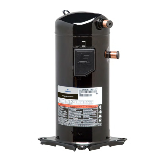
Product description General information about Copeland Scroll™ compressors These application guidelines deal with all vertical single Copeland scroll compressors from ZR24KRE to ZR190KRE for air-conditioning applications. Cooling capacity [kW] Compressor Motor R450A R513A ZR24KRE 3.06 3.54 PFJ/TFD ZR28KRE 3.60 4.17 PFJ/TFD ZR36KRE 4.58... -
Page 9: Bom Variation
IP21 T-box, no mounting parts. BOM 411 braze connections, oil sight glass, oil service connection, IP65 T-box, no mounting parts. Please refer to the Emerson price list for more details. Application range 2.4.1 Qualified refrigerants and oils... -
Page 10: Dimensions
The pressure PS is the maximum allowable pressure at the low- and high-pressure sides of the compressor. The maximum pressure value PS for the individual compressor type is printed on the nameplate of the compressor. Safety is established in compliance with the relevant standards applicable to the given product. - Page 11 Compressor A [mm] B [mm] C [mm] D [mm] model ZR108KRE to 533.2 501.1 122.1 252.7 ZR144KRE ZR160KRE & 551.5 519.5 140.4 ZR190KRE Figure 3: Dimensions for models ZR108KRE to ZR190KRE BOM411 Compressor A [mm] B [mm] C [mm] D [mm] model ZR108KRE to 533.2...
-
Page 12: Installation
Installation WARNING High pressure! Injury to skin and eyes possible! Be careful when opening connections on a pressurized item. Compressor handling 3.1.1 Transport and storage WARNING Risk of collapse! Personal injuries! Move compressors only with appropriate mechanical or handling equipment according to weight. Keep in the upright position. -
Page 13: Mounting Parts
If the compressors are mounted in tandem or used in parallel, then the hard mountings (bolt M9 5/16") are recommended. The mounting torque should be 27 ± 1 Nm. See Emerson spare parts software for references. Mounting parts: ZR24KRE to ZR190KRE - Soft mountings Alternative mounting parts for ZR24KRE to ZR190KRE –... -
Page 14: Brazing Procedures For Zr*Kre Compressors In Parallel Applications
3.3.2 Brazing procedures for ZR*KRE compressors in parallel applications Only compressor models officially approved by Emerson in the qualified configuration may be used for parallel applications. For ZR*KRE compressors in parallel applications with passive oil management, additional precautions shall be taken before brazing the oil and gas equalization ports. -
Page 15: Pressure Safety Controls
Refer to Appendix 1 for proper tightening torques. NOTE: More information about adaptors and shut-off valves can be found in the Emerson spare parts software, available at www.climate.emerson.com/en-gb/tools-resources. Pressure safety controls 3.5.1 High-pressure protection... -
Page 16: Soft Starter And Single-Phase Compressor Start Assists
This will prevent oil dilution and bearing stress on initial start-up. The crankcase heater must remain energized during compressor off cycles. NOTE: Please refer to the Spare Parts list available at www.climate.emerson.com/en-gb/tools- resources for correct crankcase heater model selection. Caution: Crankcase heaters must be properly grounded! For installation, the manufacturer/installer shall follow the recommendations below. -
Page 17: Discharge Gas Temperature Protection
Discharge gas temperature protection IMPORTANT Inadequate lubrication! Scroll set damage! All ZR*KRE compressors must be equipped with a discharge gas temperature protection. A good system control shall prevent the system from operating outside the published operating envelope and acceptable superheat range, whatever the climatic conditions and the capacity demand. -
Page 18: Discharge Line Thermostat
Figure 13: Advanced Scroll Temperature Protection (ASTP) NOTE: Depending on the heat build-up in the compressor, it may take more than one hour for the ASTP and motor protector to reset. 3.8.4 Discharge line thermostat ZR92KRE compressors have no internal discharge gas temperature protection. Therefore, an external discharge line thermostat must be installed. -
Page 19: Internal Pressure Relief Valve
▪ Snap the retainer clip over the tube and onto the thermostat. ▪ The thermostat should be placed on the discharge tube so that its body is in upward position on a horizontal tube installation. ▪ Ensure that the thermostat is not tilted. ▪... -
Page 20: Sound And Vibration
Systems with multiple compressor applications (two, three, or more) require additional oil balancing qualification between the parallel compressors. A sample compressor equipped with an external oil sight tube can be ordered from Emerson for lab testing. During the tests, records of the evaporating temperature and the bottom shell temperature shall be taken with a high sampling rate. -
Page 21: Suction Line Accumulator
migration, defrost, in reversible systems switching between the operation modes, load changes, fans or pumps cycling at low load and more. To evaluate the risk of liquid flood-back please refer to the oil dilution chart in Figure 16. Liquid level and superheat at compressor inlet have to be checked. -
Page 22: Electrical Connection
Electrical connection General recommendations The compressor terminal box has a wiring diagram on the inside of its cover. Before connecting the compressor, ensure the supply voltage, the phases and the frequency match the nameplate data. Electrical installation WARNING Conductor cables! Electrical shock! Shut off power supply before undertaking any task on electrical equipment. - Page 23 Three-phase compressors (TF*) with internal motor protection: Power circuit Control circuit Motor terminal connections Three-phase compressors are connected to the T1, T2 and T3 connections Legend B1 ..Room thermostat K1 ..Contactor B3 ..Discharge gas thermostat R2 ..Crankcase heater F1 ..
-
Page 24: Terminal Box
Ensure correct connection of cables to the compressor terminal Fusite to avoid local overheating. Cable glands have an influence on the protection class of the terminal box. Emerson strongly recommends to use appropriate cable glands according to EN 50262 in order to reach the rated protection class. -
Page 25: Terminal Box - Metal Ip65
Emerson subjects all scroll compressors to a high-voltage test after final assembly. Each motor phase winding is tested according to EN 60034-1 at a differential voltage of 1000 V plus twice the nominal voltage. - Page 26 made with the compressor charged with refrigerant. Carry out the test with a lower voltage, as described above. Disconnect all electronic devices, eg, motor protection module, fan speed control, etc prior to testing. AGL_AC_ST_ZRKRE_E_Rev01...
-
Page 27: Start-Up & Operation
System contamination! Bearing malfunction! Use only dry inert gases (for example nitrogen) for leak testing. DO NOT USE other industrial gases. The compressor has been leak-pressure tested in the Emerson factory. Therefore, it is not necessary for the system manufacturer/installer to leak-pressure test the compressor again on the assembly/system. -
Page 28: Preliminary Checks - Pre-Starting
axially seal with the scroll set, with the higher pressure on the floating seal. Consequently, until the pressures equalise, the floating seal and scroll set can be held tightly together. The highest demands are placed on the leak-proof design of the installation and on the leak testing methods –... -
Page 29: Rotation Direction
Rotation direction Scroll compressors, like several other types of compressors, will only compress in one rotational direction. Direction of rotation is not an issue with single-phase compressors since they will always start and run in the proper direction. All other three-phase compressors will rotate in either direction depending upon phasing of the power. -
Page 30: Minimum Run Time
Minimum run time 5.13 Emerson recommends a maximum of 10 starts per hour. There is no minimum off time because scroll compressors start unloaded, even if the system has unbalanced pressures. The most critical consideration is the minimum run time required to return oil to the compressor after start-up. To establish the minimum run time, a sample compressor equipped with an external oil sight glass is available from Emerson. -
Page 31: Maintenance & Repair
Maintenance & repair WARNING Conductor cables! Electrical shock! Follow the lockout/tag out procedure and the national regulations before carrying out any maintenance or service work on the system. Use compressor with grounded system only. Screwed electrical connections must be used in all applications. Refer to original equipment wiring diagrams. Electrical connections must be made by qualified electrical personnel. -
Page 32: Exchanging The Refrigerant
Leak checking shall be carried out with the following frequency: (a) once per year if the system contains between 5 and <50 tonnes CO (b) once every 6 months if the system contains between 50 and <500 tonnes CO (c) once every 3 months if the system contains more than 500 tonnes CO NOTE: The leak checking frequency can be halved if permanent leak detection systems are fitted. -
Page 33: Compressor Replacement
Since POE holds moisture more readily than mineral oil it is more difficult to remove it through the use of vacuum. Compressors supplied by Emerson contain oil with low moisture content, and it may rise during the system assembling process. Therefore it is recommended that a properly sized filter-drier is installed in all POE systems. -
Page 34: Oil Additives
Oil additives Although Emerson cannot comment on any specific product, from our own testing and past experience, we do not recommend the use of any additives to reduce compressor bearing losses or for any other purpose. -
Page 35: Troubleshooting
Troubleshooting Most in-warranty electrical failures are a result of mechanical problems (particles in the oil, liquid refrigerant in the oil, etc.) and most mechanical problems are a result of system problems. Unless the reason for the failure is found, replacing the compressor will probably lead to another compressor failure. - Page 36 Condition Cause Corrective action Compressor Check if there is continuity on the compressor external protector. If motor the compressor is warm, it may require considerable time to cool protector open down. Defective Check if the pressure control or thermostat works properly or if the system control controls are open.
- Page 37 Cause Corrective action Excessive Too high Make sure the compressor operates within the acceptable discharge compressor superheat range published by Emerson. temperature superheat Excessive cooling / Check the load design. Make sure that proper insulation is heating load or applied. Correct it as necessary.
-
Page 38: Dismantling & Disposal
Application Guidelines and Technical Information. Performance and technical data: The latest version of Copeland brand products Select software with performance data and technical data is available from the webpage www.climate.emerson.com/en-gb. Spare parts and accessories: Visit the webpage www.climate.emerson.com/en-gb/tools-resources for an online version of the Emerson spare parts and accessories software. -
Page 39: Appendix 1: Tightening Torques
3. Emerson does not assume responsibility for the selection, use or maintenance of any product. Responsibility for proper selection, use and maintenance of any Emerson product remains solely with the purchaser or end user. - Page 40 The Emerson logo is a trademark and service mark of Emerson Electric Co. Emerson Climate Technologies Inc. is a subsidiary of Emerson Electric Co. Copeland is a registered trademark and Copeland Scroll is a trademark of Emerson Climate Technologies Inc.. All other trademarks are property of their respective owners.