
Related Manuals for Bosch Conettix B465


Summary of Contents for Bosch Conettix B465
- Page 1 Conettix Universal Dual Path Communicator B465 Installation and Operation Manual...
-
Page 3: Table Of Contents
Conettix Universal Dual Path Communicator Table of contents | en Table of contents Safety Introduction About documentation Bosch Security Systems, Inc. product manufacturing dates Installation workflow System overview B465 overview PSTN reporting format compatibility 3.2.1 Phone line voltage IP communication... - Page 4 Cellular Setup / Cellular Plug-in Module 7.11.1 Network Access Point Name (APN) 7.11.2 Network Access Point User Name 7.11.3 Network Access Point Password 7.11.4 SIM PIN 7.11.5 Inbound SMS 2017.11 | 05 | F.01U.311.207 Installation and Operation Manual Bosch Security Systems, Inc.
- Page 5 11.3 Show the firmware version 11.4 Diagnostic log 11.5 Understanding network polling 11.6 Troubleshooting procedures 11.6.1 No power on the B465 11.6.2 Initialization - cellular 11.6.3 Hardware Bosch Security Systems, Inc. Installation and Operation Manual 2017.11 | 05 | F.01U.311.207...
- Page 6 Required programming to meet UL 864 12.1.6 Required programming to meet ULC-S304 12.1.7 Required programming to meet ULC-S559 12.1.8 Compatible UL listed components 12.2 Certifications 12.3 B465 Event/Report Table 2017.11 | 05 | F.01U.311.207 Installation and Operation Manual Bosch Security Systems, Inc.
-
Page 7: Safety
Failure to follow these instructions can result in a failure to initiate alarm conditions Bosch Security Systems, Inc. is not responsible for improperly installed, tested, or maintained devices. Follow these instructions to avoid personal injury and damage to the equipment. -
Page 8: Introduction
All hardware and software product names used in this document are likely to be registered trademarks and must be treated accordingly. Bosch Security Systems, Inc. product manufacturing dates Use the serial number located on the product label and refer to the Bosch Security Systems, Inc. website at http://www.boschsecurity.com/datecodes/. Installation workflow To install and configure the B465, use the workflow below and follow in order from top to bottom. - Page 9 Verify LED activity (Refer to B465 LED status indicators, page 80) Review signal strength on the cellular communicator (if required). Refer to your cellular communicator Installation Guide for more information on signal strength. Installation is complete Bosch Security Systems, Inc. Installation and Operation Manual 2017.11 | 05 | F.01U.311.207...
-
Page 10: System Overview
The B465 allows any fire and intrusion control systems with PSTN dialers and/or dry contact inputs to communicate with Bosch central station receivers over Ethernet or cellular networks through IP. This allows customers using control panels developed before the introduction of networking and cellular to eliminate costly phone lines and gain some of the modern performance that IP networking enables. - Page 11 Pulse 4/2 (1400 Hz ACK Tone) – SIA (SIA8, SIA20) The B465 links the control panel’s PSTN dialer to the internet and then to one of the Bosch Conettix receivers. The B465: – Connects with the control panel PSTN dialer (through the B465 panel line terminals) or the control panel relay outputs connected to the B465 inputs.
-
Page 12: Pstn Reporting Format Compatibility
28 VDC (control panel dialer on hook) to satisfy the control panel's phone line monitor. The B465 phone voltage is 3 to 8 VDC when the control panel attempts to communicate (off hook). 2017.11 | 05 | F.01U.311.207 Installation and Operation Manual Bosch Security Systems, Inc. -
Page 13: Ip Communication
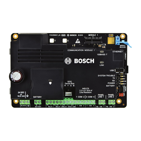
Callout ー Description 1 ー Sounder 2 ー SYSTEM TROUBLE LED 3 ー POWER LED 4 ー BATTERY LED 5 ー 3-hole mounting pattern 6 ー B46/B465 cable connection Bosch Security Systems, Inc. Installation and Operation Manual 2017.11 | 05 | F.01U.311.207... - Page 14 1 ー B10 Medium Control Panel Enclosure, door closed 2 ー B46 LED cover 3 ーEnclosure lock (D101 supplied separately) For LED patterns, refer to B465 LED status indicators, page 80. 2017.11 | 05 | F.01U.311.207 Installation and Operation Manual Bosch Security Systems, Inc.
-
Page 15: Installation
Pull any necessary wires/phone lines into the enclosure. Notice! Electromagnetic interference (EMI) can cause problems on long wire runs Bosch Security Systems, Inc. Installation and Operation Manual 2017.11 | 05 | F.01U.311.207... -
Page 16: Insert D101 Lock (Optional)
Insert the plastic LED cover into the knockout. Snap the cover into place. Make sure the cover is secure. For more information, refer to the B46 Install Guide for more information. 2017.11 | 05 | F.01U.311.207 Installation and Operation Manual Bosch Security Systems, Inc. -
Page 17: Install The B465 In The Enclosure
Insert the plug-in module into plug-in stabilizing hole X, and then into the plug-in module connector. Continue pressing the module into the connector until the retention clip engages. Refer to callouts 1, 2, and 3 in B465 overview, page 10. Bosch Security Systems, Inc. Installation and Operation Manual 2017.11 | 05 | F.01U.311.207... - Page 18 LINE 1 LINE 2 16.5VAC NC C NO PNL LINE 1 PNL LINE 2 RELAY 1 RELAY 2 RELAY 3 AUX COM BATTERY Figure 4.2: Cellular plug-in module 2017.11 | 05 | F.01U.311.207 Installation and Operation Manual Bosch Security Systems, Inc.
-
Page 19: Wiring Installation
11 ーSDI2 device bus connector (for future use) 6 ー12V AUX/COM terminals for 12 VDC auxiliary power (optional output power source, Special Application 9.9 to 13.8 V) Bosch Security Systems, Inc. Installation and Operation Manual 2017.11 | 05 | F.01U.311.207... - Page 20 Connect the common terminal of the FACP (Fire Alarm Control Panel) auxiliary power to the common (COM) terminal of the B465 auxiliary power. Do not connect to earth ground on the FACP or the B465. 2017.11 | 05 | F.01U.311.207 Installation and Operation Manual Bosch Security Systems, Inc.
-
Page 21: Control Panel To B465 Wiring For Dialer Capture
5 ー Internal Ground (AUX Power negative or internal Common) required for Commercial Fire 6 ー Control panel EOL resistor (required for supervision with callout #7) 7 ー Optional for local B465 troubles Bosch Security Systems, Inc. Installation and Operation Manual 2017.11 | 05 | F.01U.311.207... -
Page 22: Control Panel To Dry Contact Wiring
Use the cable supplied with the B46 to connect to the B465 module. Refer to System overview, page 10 section for component location. Refer to the figure below. 2017.11 | 05 | F.01U.311.207 Installation and Operation Manual Bosch Security Systems, Inc. -
Page 23: Input Loop Wiring
– Panel System Trouble – Panel AC Fail – Panel Battery Trouble – Fire Alarm – Fire Trouble – Burg Alarm – Burg Trouble – Fire Supervisory Bosch Security Systems, Inc. Installation and Operation Manual 2017.11 | 05 | F.01U.311.207... - Page 24 You do not need to install an End of Line (EOL) resistor for unused inputs (inputs are disabled by default). Notice! UL commercial fire requirement UL does not permit normally closed loops for commercial fire applications. 2017.11 | 05 | F.01U.311.207 Installation and Operation Manual Bosch Security Systems, Inc.
-
Page 25: Output Wiring
(RELAY) 3. The outputs can be connected to the control panel inputs (points or zones) to communicate the B465 status to the control panel. Each output can be configured for one output function: – System Trouble – AC Fail Bosch Security Systems, Inc. Installation and Operation Manual 2017.11 | 05 | F.01U.311.207... -
Page 26: Primary Power Source Wiring
Make the wire length as short as possible. Do not exceed 50 ft. (15 m). Maximum wire resistance should not exceed 0.65 ohms. Connect the wire to the control panel. 2017.11 | 05 | F.01U.311.207 Installation and Operation Manual Bosch Security Systems, Inc. - Page 27 Install the negative voltage lead on the leftmost terminal. Install the positive voltage lead on the terminal beween the the negative lead and the earth ground terminal. Bosch Security Systems, Inc. Installation and Operation Manual 2017.11 | 05 | F.01U.311.207...
- Page 28 The tests complete in 10 to 30 seconds. If the B465 fails a test, a System Trouble occurs. Trouble LED's turn on or outputs activate depending on configuration. 2017.11 | 05 | F.01U.311.207 Installation and Operation Manual Bosch Security Systems, Inc.
-
Page 29: D1640-120Wi Transformer Wiring (Optional)
Maintain a 0.250 in (6.4 mm) space between the battery terminals, battery wiring, and all other wiring. Battery wiring cannot share the same conduit, conduit fittings, or conduit knockouts with other wiring. Bosch Security Systems, Inc. Installation and Operation Manual 2017.11 | 05 | F.01U.311.207... - Page 30 3 ー 0.25 in (6.4 mm) minimum 4 ー Battery terminals. BATTERY+ is non-power limited 5 ー Battery wires (red and black) 6 ー 12 VDC, 7-18 Ah sealed lead-acid rechargeable battery (D126/D1218) 2017.11 | 05 | F.01U.311.207 Installation and Operation Manual Bosch Security Systems, Inc.
- Page 31 Exceeding the maximum output ratings or installing the transformer in an outlet that is routinely switched off causes heavy discharges. Routine heavy discharges can lead to premature battery failure. Bosch Security Systems, Inc. Installation and Operation Manual 2017.11 | 05 | F.01U.311.207...
- Page 32 10.2 VDC - Minimum operational voltage. Recharge cycle AC ON - Battery charging begins and AC Restoral Reports sent. 13.4 V - Battery Restoral Report sent. Battery float charged. 2017.11 | 05 | F.01U.311.207 Installation and Operation Manual Bosch Security Systems, Inc.
-
Page 33: Ip Communicators
The B465 supervises the plug-in cellular communicator when it is configured as either the preferred network technology or the alternate network technology. Supervision ensures reliable end to end network communications. If the plug-in cellular communicator does not Bosch Security Systems, Inc. Installation and Operation Manual 2017.11 | 05 | F.01U.311.207... -
Page 34: Report Routing
Enabled). You are using two network technologies (Cellular and Ethernet), and both the primary receiver and the secondary receiver are configured to receive both network technologies (Cellular and Ethernet). 2017.11 | 05 | F.01U.311.207 Installation and Operation Manual Bosch Security Systems, Inc. - Page 35 5 ー Cellular Carrier 6 ー Internet 7 ー Optional VPN tunnel 8 ー Router firewall 9 ー Corporate network 10 ー Primary Conettix receiver 11 ー Secondary Conettix receiver Bosch Security Systems, Inc. Installation and Operation Manual 2017.11 | 05 | F.01U.311.207...
-
Page 36: Compatible Central Station Receivers
To enable encryption for IP network communications, refer to the AES Encryption parameters in Primary Receiver, page 60 and Secondary Receiver, page 63. Compatible central station receivers Sending Conettix IP reports requires a Bosch central station receiver. The following receivers are compatible with B465: –... -
Page 37: Configuration And Diagnostics
The B465 USB driver (RBUS1CP.inf) file is available on the supplied user CD. You need to install this file only once on the target computer. Installing the driver from the web: From your Internet browser, go to: http://www.boschsecurity.com to open the Bosch Web site. Select the web site for your region and country. -
Page 38: Install Teraterm
Microsoft serial communication program, when Windows installs. If HyperTerminal is not installed, install it from the Windows XP installation disc, or install Tera Term from the B465 user CD. 2017.11 | 05 | F.01U.311.207 Installation and Operation Manual Bosch Security Systems, Inc. - Page 39 Install the serial communication program that supports your configuration (Hyper Terminal or Tera Term), depending on your computer’s operating system. Notice! Tera Term is preferred in all applications as its operation is understood by Bosch Technical Support if assistance is required. Installing Tera Term...
- Page 40 Figure 6.3: Selecting the Terminal Setup window Change the default setting of CR to LF from the Receive drop-down menu and click OK. Figure 6.4: Changing the Receive: option to LF Click Save setup. 2017.11 | 05 | F.01U.311.207 Installation and Operation Manual Bosch Security Systems, Inc.
-
Page 41: Log In
From Windows, start a terminal session by launching Hyper Terminal on Windows Vista/ Windows 7/Windows 8 Windows, or launching Tera Term on Windows XP or earlier. Bosch Security Systems, Inc. Installation and Operation Manual 2017.11 | 05 | F.01U.311.207... - Page 42 Please write down the password. If you forget your password we can only default the module after it is returned and will not be able to help you restore the module in the field. 2017.11 | 05 | F.01U.311.207 Installation and Operation Manual Bosch Security Systems, Inc.
-
Page 43: Main Menu
The B465 automatically logs out of the menus after 5 minutes of inactivity. All unsaved changes are lost. You must reenter the passcode to return to the main menu. Bosch Security Systems, Inc. Installation and Operation Manual 2017.11 | 05 | F.01U.311.207... -
Page 44: Menu Map
Disabled 200 Seconds - (UL 1610) 128 Bits 300 Seconds- (NFPA 72 2010) 192 Bits 1 Hour - (NFPA 72 2013) 256 Bits 4 Hours 24 Hours 2017.11 | 05 | F.01U.311.207 Installation and Operation Manual Bosch Security Systems, Inc. - Page 45 Comm Fail removes line 2 phone voltage RPS Passcode: “999999” Enabled Answer RPS Over Network Disabled Back Back Disabled Test Report Interval 4 hours 6 hours 12 hours 24 hours Bosch Security Systems, Inc. Installation and Operation Manual 2017.11 | 05 | F.01U.311.207...
- Page 46 Reset To Factory Default Exit Communicator Test Menu Clear/Reset Status Module Operations Verbose Mode Firmware Update All Verbose Modes Off Exit Settings have changed. Save before exit 2017.11 | 05 | F.01U.311.207 Installation and Operation Manual Bosch Security Systems, Inc.
-
Page 47: Status
This option shows various parameters related to the cellular device Status Menu such as UDP packets transmitted and received, the carrier name, available towers, and data class. Bosch Security Systems, Inc. Installation and Operation Manual 2017.11 | 05 | F.01U.311.207... - Page 48 Ethernet Network. This field displays the connection status to the Ethernet network. This field displays either OK, or Error. Encryption This field displays either Normal, or Trouble: 2017.11 | 05 | F.01U.311.207 Installation and Operation Manual Bosch Security Systems, Inc.
- Page 49 This field displays the current signal strength. One of the following appears; Very good, Good, Marginal, Unacceptable, or Unavailable. Module Status Module Status shows only when there is a trouble status. Bosch Security Systems, Inc. Installation and Operation Manual 2017.11 | 05 | F.01U.311.207...
- Page 50 Enter the passcode to launch the USB menu. Enter [2] Advanced Status. The Advanced Status option appears. The following section describes the description of the Advanced Status menu information. 2017.11 | 05 | F.01U.311.207 Installation and Operation Manual Bosch Security Systems, Inc.
- Page 51 This field shows the carrier network providing service. Data Status This field shows one of the following; Disconnected, Connecting, or Connected. Signal Strength This field shows the current signal strength in dbm. Bosch Security Systems, Inc. Installation and Operation Manual 2017.11 | 05 | F.01U.311.207...
-
Page 52: Standard Communication Configuration, 3 = Advanced Communication
Enter the B465 passcode. Select [8] Maintenance. Enter the desired options. Refer to the table below for Maintenance and Maintenance sub-menu descriptions. Option Press to Description start 2017.11 | 05 | F.01U.311.207 Installation and Operation Manual Bosch Security Systems, Inc. -
Page 53: Firmware Update
Diagnostic Available options include: – Modify Diagnostic Settings. Use this option to determine which type of messages display during diagnostics. This option is for use only under Bosch direction. A sub-menu of options includes: – Receiver Communications Verbose Mode –... - Page 54 6. The B465 USB login window appears, listing the current software version and build. Figure 6.11: B465 USB login window Select option 8 Maintenance. Select option 5 Firmware Update and press [Enter]. 2017.11 | 05 | F.01U.311.207 Installation and Operation Manual Bosch Security Systems, Inc.
- Page 55 From the Tera Term main menu, select File>Transfer>XMODEM>Send. In the XMODEM Send dialog window, navigate to the folder location and select the firmware update software you downloaded. The file ends in *.kfw extension. Bosch Security Systems, Inc. Installation and Operation Manual 2017.11 | 05 | F.01U.311.207...
- Page 56 Conettix Universal Dual Path Communicator Figure 6.12: File navigation Click Open to start the firmware update. The Tera Term: XMODEM Send dialog box opens and indicates the update process. 2017.11 | 05 | F.01U.311.207 Installation and Operation Manual Bosch Security Systems, Inc.
- Page 57 11. Log back into Tera Term as described previously to re-establish communication from your laptop to the B465 . Communication between the B465, receiver(s), and the connected control panel is restored. Bosch Security Systems, Inc. Installation and Operation Manual 2017.11 | 05 | F.01U.311.207...
-
Page 58: Communication Configuration
(digits) Modem IIe / IIIa Modem II Contact ID Pulse 1400/2300 (3x1, 3x1e) Pulse 1400/2300 (4x2) SIA DC-03 Tab. 7.3: Reporting format / Account number length 2017.11 | 05 | F.01U.311.207 Installation and Operation Manual Bosch Security Systems, Inc. -
Page 59: Preferred Network Technology
USB Menu Location [2] Standard Communication Configuration > [3] Preferred Network Technology - or - [3] Advanced Communication Configuration > [1] Account Setup > [3} Preferred Network Technology Bosch Security Systems, Inc. Installation and Operation Manual 2017.11 | 05 | F.01U.311.207... -
Page 60: Cloud (Remote Connect)
Enabled - use the on-board Ethernet connector for Cloud (Remote Connect) connections. – Disabled - do not use the on-board Ethernet connector. Remote Connect is a Bosch Cloud-based Service that allows RPS to connect to the B465 for programming and diagnostics. Notice! -
Page 61: Ethernet Ip Address / Host Name
If the B465 does not receive an ACK to a heartbeat poll after the retry count is met, it creates a Communication Trouble event. USB Menu Location [2] Standard Communication Configuration > [4] Primary Receiver > [3] Ethernet Supervision Time - or - Bosch Security Systems, Inc. Installation and Operation Manual 2017.11 | 05 | F.01U.311.207... -
Page 62: Cellular Ip Address / Host Name
[3] Advanced Communication Configuration > [2] Receiver Setup > [1] Primary Receiver > [5] Cellular Supervision Time 7.7.6 AES Encryption, Key Size Default: No Encryption (Disabled) Selections: – No Encryption (Disabled) – 128 bits - 16 bytes 2017.11 | 05 | F.01U.311.207 Installation and Operation Manual Bosch Security Systems, Inc. -
Page 63: Aes Encryption Key
IP Address and Domain Name formats USB Menu Location [3] Advanced Communication Configuration > [2] Receiver Setup > [2] Secondary Receiver > [2] Ethernet IP Address / Host Name Bosch Security Systems, Inc. Installation and Operation Manual 2017.11 | 05 | F.01U.311.207... -
Page 64: Port Number
[3] Advanced Communication Configuration > [2] Receiver Setup > [2] Secondary Receiver > [4] Cellular IP Address / Host Name 7.9.5 Cellular Supervision Time Default: 1 hour Selections: – No polling – 90 seconds – 180 seconds 2017.11 | 05 | F.01U.311.207 Installation and Operation Manual Bosch Security Systems, Inc. -
Page 65: Aes Encryption, Key Size
USB Menu Location [3] Advanced Communication Configuration > [3] Ethernet Setup > [1] IPv6 Configuration > [1] IPv6 Mode 7.10.2 IPv6 DNS Server IP Address Default: blank Bosch Security Systems, Inc. Installation and Operation Manual 2017.11 | 05 | F.01U.311.207... -
Page 66: Alternate Ipv6 Dns Server Ip Address
Disabled - Set this parameter to Disabled if there is no DHCP service. Manually set the IP Address, IP Default Gateway, and IP DNS Server Address. DHCP requires a DHCP server. 2017.11 | 05 | F.01U.311.207 Installation and Operation Manual Bosch Security Systems, Inc. -
Page 67: Ipv4 Address
IP Address and Domain Name formats USB Menu Location [3] Advanced Communication Configuration > [3] Ethernet Setup > [2] IPv4 Configuration > [5] IPv4 DNS Server IP Address Bosch Security Systems, Inc. Installation and Operation Manual 2017.11 | 05 | F.01U.311.207... -
Page 68: Alternate Ipv4 Dns Server Ip Address
This parameter specifies the time-out for ARP cache entries. USB Menu Location [3] Advanced Communication Configuration > [3] Ethernet Setup > [4] ARP cache timeout (min) 7.10.14 B465 Hostname Default: [blank] 2017.11 | 05 | F.01U.311.207 Installation and Operation Manual Bosch Security Systems, Inc. -
Page 69: Tcp/Udp Port Number
This parameter sets the network access point name (APN). Enter up to 99 characters. The field is case sensitive. Notice! The default APN, EAAA.BOSCH.VZWENTP, is new The previous default, wyless.apn, is still valid. There is no need to change the APN for existing accounts. -
Page 70: Sim Pin
[3] Advanced Communication Configuration > [4] Cellular Setup > [3] Reporting Delay for Low Signal Strength (min.) 7.11.7 Reporting Delay for No Towers (minutes) Default: 0 Selections: 0 (disabled) - 60 (minutes) 2017.11 | 05 | F.01U.311.207 Installation and Operation Manual Bosch Security Systems, Inc. -
Page 71: Ipv4 Dns Server Ip Address
The default test address works for most networks. Further information IP Address and Domain Name formats USB Menu Location [3] Advanced Communication Configuration > [4] Cellular Setup > [5] IPv4 DNS Server IP Address Bosch Security Systems, Inc. Installation and Operation Manual 2017.11 | 05 | F.01U.311.207... -
Page 72: System Configuration
1400 Hz - for pulse formats that require a 1400 Hz handshake tone – SIA - handshake tone for SIA DC-03 format – Modem II - handshake tone for Bosch (Radionics) Modem II format – Modem IIe/IIIa - handshake tone for Bosch (Radionics) Modem IIe and Modem IIIa... -
Page 73: Primary Power Fail Delay
The battery voltage must be below 12.1 volts for 16 seconds before the B465 creates a low battery event. It takes between 10 and 60 seconds to sense a missing battery. Bosch Security Systems, Inc. Installation and Operation Manual 2017.11 | 05 | F.01U.311.207... -
Page 74: Battery Faults Send Reports
Enabled - when there is a fault on the tamper circuit, the B465 sets the trouble output. – Disabled - the B465 does not set the trouble output for faults on the tamper circuit. 2017.11 | 05 | F.01U.311.207 Installation and Operation Manual Bosch Security Systems, Inc. -
Page 75: Communication Failure Action
PNL LINE 2 terminals (terminals for panel phone line 2). – Disabled - the B465 does not remove voltage to the PNL LINE 2 terminals for communication failure events. Bosch Security Systems, Inc. Installation and Operation Manual 2017.11 | 05 | F.01U.311.207... -
Page 76: Module Supervision
Disabled - prevents automatic RPS initiated connections over the network. USB Menu Location [4] System Configuration > [7] RPS Settings > [2] Answer RPS over Network USB Terminal Passcode Default: B465 Selections: 4-23 ASCII characters (no spaces) 2017.11 | 05 | F.01U.311.207 Installation and Operation Manual Bosch Security Systems, Inc. -
Page 77: Test Report
To save your changes in RPS, connect the B465 with RPS. In the Panel Synchronization window, click Receive & Overwrite RPS Data. USB Menu Location [4] System Configuration > [8] Test Report Settings > [1] Test Report Interval Bosch Security Systems, Inc. Installation and Operation Manual 2017.11 | 05 | F.01U.311.207... -
Page 78: Input Configuration
Contact ID 380, Sensor Trouble report. When the sensor loop is open, the B465 sends a Contact ID 371, Protection Loop Open report. USB Menu Location [5] Input Configuration > [1,2,3,4] Input 1 (to 4) 2017.11 | 05 | F.01U.311.207 Installation and Operation Manual Bosch Security Systems, Inc. -
Page 79: Output Configuration
B465 activates this output. – Disabled - the B465 does not activate this output. USB Menu Location [6] Output Configuration > [1,2,3] Input 1 (to 3) Bosch Security Systems, Inc. Installation and Operation Manual 2017.11 | 05 | F.01U.311.207... -
Page 80: Maintenance And Troubleshooting
The LED for panel phone line 2 is located to the left of the PNL LINE 2 terminals. Flash pattern Function Phone line 1/Phone line 2 OFF-HOOK. On Steady Phone line 1/Phone line 2 off the hook for more than 120 seconds. Flashing 2017.11 | 05 | F.01U.311.207 Installation and Operation Manual Bosch Security Systems, Inc. - Page 81 Green (2 lights) * One green LED indicates the minimum installation level. Tab. 11.7: Cellular module signal strength LED patterns A single blue Status LED indicates the module status. Bosch Security Systems, Inc. Installation and Operation Manual 2017.11 | 05 | F.01U.311.207...
- Page 82 2 minutes, or there is a On Steady configuration issue. Tab. 11.9: SYSTEM TROUBLE LED descriptions 2017.11 | 05 | F.01U.311.207 Installation and Operation Manual Bosch Security Systems, Inc.
- Page 83 Flashing (two flashes) On Steady correct plug-in module is firmly inserted into the module connector. Verify the latest firmware is installed to support the module you have. Bosch Security Systems, Inc. Installation and Operation Manual 2017.11 | 05 | F.01U.311.207...
- Page 84 Try positioning the antenna in a different location. If that does not work, try changing to a different service provider or cellular plug-in module that using the other technology. 2017.11 | 05 | F.01U.311.207 Installation and Operation Manual Bosch Security Systems, Inc.
- Page 85 Tab. 11.11: POWER LED descriptions POWER LED Flash pattern Function Indicates a good Input Power level. On Steady Indicates Input Power is low (brownout) or failure. Flashing Bosch Security Systems, Inc. Installation and Operation Manual 2017.11 | 05 | F.01U.311.207...
-
Page 86: B46 Led Status And Sounder
SYSTEM TROUBLE Flashing (one flash) - Ethernet table for more information. Flashing Indicates cellular communication errors. Refer to SYSTEM TROUBLE Flashing (two flashes) - Cellular table for more information. Flashing 2017.11 | 05 | F.01U.311.207 Installation and Operation Manual Bosch Security Systems, Inc. - Page 87 Is in an off state during the power up sequence. Tab. 11.15: POWER LED descriptions BATTERY LED Flash pattern Function Indicates normal operations. Indicates low battery voltage. Flashing (one flash) Bosch Security Systems, Inc. Installation and Operation Manual 2017.11 | 05 | F.01U.311.207...
-
Page 88: Show The Firmware Version
1 sec pause after each digit. The following is an example: The version 1.4.3 would show as LED flashes: [3 second pause] *__****__*** [3 second pause, then normal operation]. 2017.11 | 05 | F.01U.311.207 Installation and Operation Manual Bosch Security Systems, Inc. -
Page 89: Diagnostic Log
Your settings for these parameters determine how the system works, but depend on the security level needed. For more information regarding proper data plans and installation parameters related to network polling, refer to Bosch Cellular Service User Guide (P/N: F01U273558). 11.6 Troubleshooting procedures Refer to the following section for troubleshooting hardware and software issues. -
Page 90: Hardware
If the problem continues after rebooting the system, replace the SIM card with a different card. A new SIM card might require the B465 to be reconfigured to the new card’s parameters (if using a different carrier or provider). 2017.11 | 05 | F.01U.311.207 Installation and Operation Manual Bosch Security Systems, Inc. -
Page 91: Cellular Network Registration
COM error occurs when trying to connect to the B465 using the USB serial program. The following screen shows. Figure 11.2: COM port error Solution: Click OK. Click File -> New Connection. Bosch Security Systems, Inc. Installation and Operation Manual 2017.11 | 05 | F.01U.311.207... -
Page 92: Testing The System
After system installation and any B465 programming, perform a complete system test (UL 864 requirement). A complete system test includes testing the control panel, B465,all devices, and communication paths for proper operation. 2017.11 | 05 | F.01U.311.207 Installation and Operation Manual Bosch Security Systems, Inc. - Page 93 Conettix Universal Dual Path Communicator Maintenance and troubleshooting | en Bosch Security Systems, Inc. Installation and Operation Manual 2017.11 | 05 | F.01U.311.207...
-
Page 94: Specifications And Certifications
79 mm x 128 mm x 38 mm (3.11 in. x 5.03 in. x 1.50 in.) Wiring USB cable Use a Bosch supported Type A male-to-male USB cable such as the B99 cable (F01U278853). Compatible enclosures B10R Medium Control Panel Enclosure - 35.6 cm x 31.8 cm x 7.6 cm (14 in. x 12.5 in. x 3 in.) B10 Medium Control Panel Enclosure - 35.6 cm x 31.8 cm x 7.6 cm (14 in x 12.5 in x 3 in) - Page 95 B441 Conettix Plug-in CDMA Cellular Communicator B442 Conettix Plug-in GPRS Cellular Communicator B443 Conettix Plug-in HSPA+ Cellular Communicator (SIM card required) B444 Conettix Plug-in LTE Cellular Communicator (Verizon) Bosch Security Systems, Inc. Installation and Operation Manual 2017.11 | 05 | F.01U.311.207...
-
Page 96: B465 Power Supply Specifications
Open - 3.7 to 5.0 VDC 1 to 4 Normal - 2.0 to 3.0 VDC Short - 0.0 to 1.3 VDC Short circuit current - 2.5 mA 2017.11 | 05 | F.01U.311.207 Installation and Operation Manual Bosch Security Systems, Inc. -
Page 97: Application Environment
For Commercial Burglary applications, house all communicators in tampered enclosures. You must wire system troubles back to the control panel as the B46 can not be used in the D8108A enclosure. Bosch Security Systems, Inc. Installation and Operation Manual 2017.11 | 05 | F.01U.311.207... -
Page 98: Standby Battery Requirements And Calculations
Value = Minutes of alarm operation/60 as per the Application environment table. Total Ah requirements must not exceed the Ah capacity of batteries: – One D126 Battery = 7 Ah – One D1218 Battery = 18 Ah 2017.11 | 05 | F.01U.311.207 Installation and Operation Manual Bosch Security Systems, Inc. -
Page 99: 24 Vdc Input Power Requirements
Notice! Maximum power supply current for Total B in the table above is 675 mA, and the maximum power supply current for Total C is 830 mA. Bosch Security Systems, Inc. Installation and Operation Manual 2017.11 | 05 | F.01U.311.207... -
Page 100: Required Programming To Meet Ul 864
Battery Monitoring, page Enabled/Disabled Enabled Battery faults send Enabled/Disabled Enabled - if sending reports, page 74 report from B465, disabled if using relay outputs to control panel 2017.11 | 05 | F.01U.311.207 Installation and Operation Manual Bosch Security Systems, Inc. - Page 101 Sole path times 4 hours, 24 hours depends on the NFPA standard being used, always consult your local AHJ. 90 seconds, 180 seconds, 200 seconds, 300 seconds, 1 hour Bosch Security Systems, Inc. Installation and Operation Manual 2017.11 | 05 | F.01U.311.207...
-
Page 102: Required Programming To Meet Ulc-S304
3 hours Supervision interval for IP communications Ethernet Supervision Time, page 61, set to 180 seconds Cellular Supervision Time, page 62, set to 180 seconds 2017.11 | 05 | F.01U.311.207 Installation and Operation Manual Bosch Security Systems, Inc. - Page 103 Conettix Universal Dual Path Communicator Specifications and certifications | en 103 Bosch Security Systems, Inc. Installation and Operation Manual 2017.11 | 05 | F.01U.311.207...
-
Page 104: Compatible Ul Listed Components
Opt. Opt. Opt. Opt. Opt. Plug-in Cellular Communicator B444 Conettix Opt. Opt. Opt. Opt. Opt. Opt. Plug-in Cellular Communicator Conettix D6600 Opt. Opt. Communication s Receiver/ Gateway 2017.11 | 05 | F.01U.311.207 Installation and Operation Manual Bosch Security Systems, Inc. - Page 105 UL 985 Intrusion B10/B10R Medium Control Panel Enclosure B11/B11R Small Control Panel Enclosure Mounting Plate for D8103 Enclosure D8103 Universal Control Panel Enclosure D8108A Attack Resistant Enclosure Bosch Security Systems, Inc. Installation and Operation Manual 2017.11 | 05 | F.01U.311.207...
- Page 106 UL Listed Class 2 Wired Transformer 16.5 VAC 40 VA 60 D1640-CA UL Listed Class 2 Plug-in Transformer 120 VAC primary, 16.5 VAC 40 VA secondary ICP-EZTS Tamper Switch Required if using a plug-in transformer 2017.11 | 05 | F.01U.311.207 Installation and Operation Manual Bosch Security Systems, Inc.
-
Page 107: Certifications
ULC-S559 - Fire Signal Receiving Centres and Systems ULC-ORD-C1023 - Household Burglar Alarm System Units ULC-ORD-C1076 - Proprietary Burglar Alarm Units and Systems ICES-003 - Digital Apparatus Bosch Security Systems, Inc. Installation and Operation Manual 2017.11 | 05 | F.01U.311.207... -
Page 108: B465 Event/Report Table
FIRE SUPERVISORY (restoral) Supervisory returns to normal after being shorted, the B465 creates a Panel Fire Supervisory Restoral event and sends a, FIRE FIRE SUPERVISORY Restoral report. 2017.11 | 05 | F.01U.311.207 Installation and Operation Manual Bosch Security Systems, Inc. - Page 109 When the battery voltage for the B465 is low, the B465 makes a low battery event and sends an LOW SYSTEM BATT report (iii = 000). Bosch Security Systems, Inc. Installation and Operation Manual 2017.11 | 05 | F.01U.311.207...
- Page 110 BATTERY MISSING (restoral) returns to normal after a battery missing event, the B465 makes a battery restoral event and sends a BATTERY MISSING Restoral report (iii = 000). 2017.11 | 05 | F.01U.311.207 Installation and Operation Manual Bosch Security Systems, Inc.
- Page 111 Plug-in cellular module, SIM PIN locked – Plug-in cellular module, SIM PIN not needed – Cellular, configuration incorrect – Cellular, not registered for Bosch Cellular Service – Cellular, invalid access point – Cellular IP address incorrect – Cellular, low signal –...
- Page 112 When a B465 input returns to normal after PROTECTION LOOP OPEN being open, the B465 makes an input open (restoral) trouble event and sends a, PROTECTION LOOP OPEN Restoral report. 2017.11 | 05 | F.01U.311.207 Installation and Operation Manual Bosch Security Systems, Inc.
- Page 113 When the B465 is configured to send test PERIODIC TEST (system trouble reports and there is a module or input fault present) it sends a PERIODIC TEST (system trouble present) report. Bosch Security Systems, Inc. Installation and Operation Manual 2017.11 | 05 | F.01U.311.207...
- Page 115 Bosch Security Systems, Inc. Bosch Sicherheitssysteme GmbH 130 Perinton Parkway Robert-Bosch-Ring 5 Fairport, NY 14450 85630 Grasbrunn Germany www.boschsecurity.com © Bosch Security Systems, Inc., 2017...