Table of Contents
Quick Links
General User Manual
DAC Monitoring and
Control System
DAC Tower Meter v3.x/v4.x
Version/Lang.
2-0-2/EN
Status
released
Date of Issue
2018-01-29
Classification
For the DAC Monitoring and Control System Customers
File
DL-PDL_General-User-Manual_ve_2-0-2.docx
Pages
91
Abstract
This user manual helps the operator to install and configure the Data Logger
and Tower Meter as part of the commissioning activity, look up the monitoring
results and manage the alarms.
Legal notice
Copyright law protects the entire content of this publication. No part of this
publication may be reproduced, stored in a retrieval system or transmitted in
DL-PDL_General-User-Manual_ve_2-0-2.docx
DAC Data Logger v2.x
Page 1
Table of Contents

Summary of Contents for DAC Data Logger v2 Series
- Page 1 2-0-2/EN Status released Date of Issue 2018-01-29 Classification For the DAC Monitoring and Control System Customers File DL-PDL_General-User-Manual_ve_2-0-2.docx Pages Abstract This user manual helps the operator to install and configure the Data Logger and Tower Meter as part of the commissioning activity, look up the monitoring results and manage the alarms.
- Page 2 DAC System reserves the right to amend this document at any time without prior notice.
-
Page 3: Table Of Contents
Purpose of the Document ..................7 Scope ........................... 7 General Information ....................9 Quality Control ......................9 Overview of DAC Monitoring and Control System ..........10 Safety Instructions ....................11 Special tools ......................12 Installation of the Data Logger / Tower Meter ............13 Prerequisites ...................... - Page 4 DAC Monitoring and Control System User Manual Data Logger and Tower Meter 9.10.3 Alarm description ..................... 62 Dashboard ......................... 66 Trends ........................69 Environment ......................71 Alarms ........................72 ATS Function ......................73 14.1 Introduction ....................... 73 14.2 General Settings ATS ....................76 14.3...
-
Page 5: History Of Changes And Approval
DAC Monitoring and Control System User Manual Data Logger and Tower Meter 1 History of Changes and Approval Changes Version Status Date of Author Details Issue 1-2-1Beta Release 11.08.2016 Christian Brand Valid for SW Release < 1.0.14 and ... -
Page 6: Terms And Definitions
DAC Monitoring and Control System User Manual Data Logger and Tower Meter 2 Terms and Definitions Term Definition Direct Antenna Control Junction Box DAC Monitoring System Direct Antenna Control System Data Logger Tower Meter Return loss in dB Transmission value in Volt... -
Page 7: Introduction
DAC Monitoring and Control System User Manual Data Logger and Tower Meter 4 Introduction The Monitoring and Control System is an end to end solution for the rf-system in the broadcast towers. With the Monitoring and Control System the operator can detect and prevent... - Page 8 DAC Monitoring and Control System User Manual Data Logger and Tower Meter Out of scope of this manual is the set up and going life of the Analytics-SW or the detailed instruction of the installation procedures for Sensors, Junction boxes and the cables.
-
Page 9: General Information
2. Supplier production quality control procedure 3. Supplier product testing 4. DAC System functional test on PO (purchase order) The DAC System products are produced in Switzerland and Italy by companies with quality certificates acc. to the ISO standard. -
Page 10: Overview Of Dac Monitoring And Control System
DAC Monitoring and Control System User Manual Data Logger and Tower Meter 5 Overview of DAC Monitoring and Control System The Monitoring and Control System consists of the following products: Component Abbr. Description Sensor A monitoring Sensor is mounted at the input of each antenna and power splitter/divider. -
Page 11: Safety Instructions
Monitoring System products in the network and most importantly analyse centrally all monitoring data. DAC System SMART Control is a subsystem of the DL/PDL. It controls amplifiers to increase the safety of the RF-installation. SMART Control is fast, reliable and operates with multiple decision criteria. -
Page 12: Special Tools
During the installation, the Monitoring System facilitated guides has to be followed. If situation occur which are not described and covered by the user manual, DAC System has to be contacted immediately before any further actions are taken. ... -
Page 13: Installation Of The Data Logger / Tower Meter
DAC Monitoring and Control System User Manual Data Logger and Tower Meter 09120042606 Han 4Brid-M-c + 2LWL-M-HCS-c (K) 09150006101 Han D M Crimp Contact Ag 1,5 QMM-AWG16 8 Installation of the Data Logger / Tower Meter 8.1 Prerequisites That a successful installation of the DL/PDL is possible, the following conditions need to be fulfilled: ... -
Page 14: Installation Of The 19" Subrack
DAC Monitoring and Control System User Manual Data Logger and Tower Meter 8.3 Installation of the 19” subrack Rear view Data Logger DL: Hybrid connector Sub-D9 (f) AC power supply 1 and 2 Label to connect the connector, RS- DL/PDL... -
Page 15: Data Logger And Tower Meter Interfaces
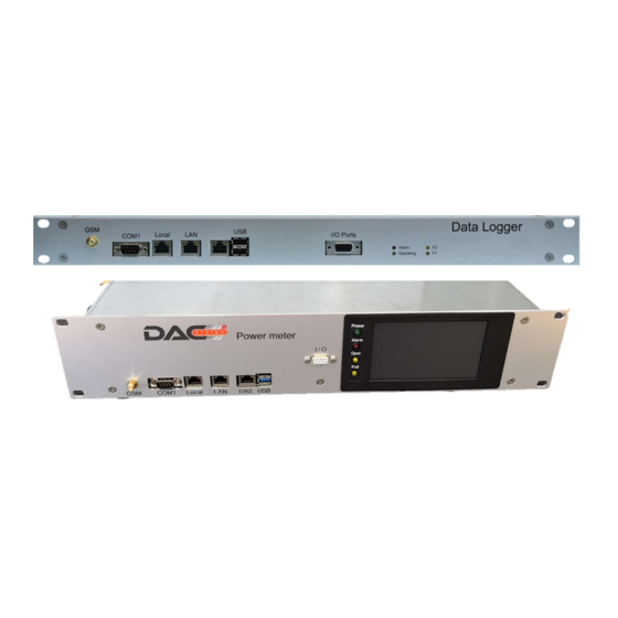
DAC Monitoring and Control System User Manual Data Logger and Tower Meter 8.4 Data Logger and Tower Meter interfaces Front view Data Logger DL: GSM antenna Ethernet SMA connector interface to IO Interface connect the Ethernet ATSB for interface to... -
Page 16: I/O Interface (Ports)
DAC Monitoring and Control System User Manual Data Logger and Tower Meter In case the system is not responding but the green LED is on (system powered), it is recommended to unplug all power supplies/switch-off the PDL to restart the system. The initial set-up time is around 2 minutes (starting the operating system and the application). -
Page 17: Wlan/Wi-Fi - Module
DAC Monitoring and Control System User Manual Data Logger and Tower Meter The SIM card needs to be entered on the lower side of the CPU in the following position: 8.7 WLAN/Wi-Fi - Module The WLAN/Wi-Fi - module mini – PCI express card is installed in the right position of the CPU board. - Page 18 DAC Monitoring and Control System User Manual Data Logger and Tower Meter DL-PDL_General-User-Manual_ve_2-0-2.docx Page 18...
-
Page 19: Configuration Of The Monitoring And Control System
DAC Monitoring and Control System User Manual Data Logger and Tower Meter 9 Configuration of the Monitoring and Control System In case, you change and save a configuration in the Web browser use F5 to refresh. Status information, alarms, dashboard, etc. After refresh the application, jumps back to the Dashboard. - Page 20 DAC Monitoring and Control System User Manual Data Logger and Tower Meter Change Password Select New Select „User“ Add User Profiles Add user profile: the email address and mobile number are only used for the Define: function “password Login name forgotten”.
-
Page 21: Principle User Interaction
DAC Monitoring and Control System User Manual Data Logger and Tower Meter 9.2 Principle user interaction The columns can be sorted (high low alphabetical) Login Information If a subject is selected User Manual the tab opens up, the for this SW... -
Page 22: Configuration Of The Dl/Pdl
DAC Monitoring and Control System User Manual Data Logger and Tower Meter 9.3 Configuration of the DL/PDL 9.3.1 General With this button the configuration Set the Automatically Sub-Menu as information of all system elements are properties of this the system... -
Page 23: Maintenance Mode Configuration
DAC Monitoring and Control System User Manual Data Logger and Tower Meter Caution: A license key must be entered to configure Monitoring Points (sensors and rf- detectors. In case the sensor configuration cannot be saved, this is an indication that the amount of licensed Monitoring Points are exceeded. -
Page 24: Ntp Configuration
DAC Monitoring and Control System User Manual Data Logger and Tower Meter Clicking this button will activate the mode for the time as set in the right box. By entering the Maintenance Mode again, the Mode can be switched off at any time. - Page 25 DAC Monitoring and Control System User Manual Data Logger and Tower Meter If the LAN port is activated, the MAC address is displayed Select DHCP or Static IP addressing and add If an ATSB on the 3rd related configurations, Ethernet port is used, the click “Save”...
-
Page 26: Mobile Configuration
DAC Monitoring and Control System User Manual Data Logger and Tower Meter 9.3.5 Mobile configuration Enter SIM PIN if a GSM- module is added in the system (see also chapter 8.6). To position the mobile data antenna at the best place with the maximum signal strength; we recommend measuring the RF-signal before starting the mobile data connection, please see chapter diagnostics 18.1. -
Page 27: Tunnel Configuration
DAC Monitoring and Control System User Manual Data Logger and Tower Meter Caution The format of the mobile-number has to follow the international format: +Int-local-number; example for Switzerland: +41793456789 Sending alarm SMS via Modem only works if a GSM-module and SIM card is inserted. -
Page 28: Smtp Configuration
URL: please enter the Site Name, we propose the following: Site Name - Number; example: albis-01 URL: albis-01.tunnel.dacsystem.ch Caution Make sure the RVTS is subscribed from DAC System, to have the service available in time. 9.3.7 SMTP configuration Default parameters are using email server (SMTP). -
Page 29: Snmp Configuration
DAC Monitoring and Control System User Manual Data Logger and Tower Meter 9.3.8 SNMP configuration Caution The SNMP functions “Traps” and/or “Agent” can be used only if the license key enables SNMP alarms are forwarded only via SNMP if the related alarm is activated in the alarm configuration menu. - Page 30 DAC Monitoring and Control System User Manual Data Logger and Tower Meter The forwarding of the Monitoring Data with traps in a network with hundreds of sensors and rf- detectors with a short polling cycle of n times per minute could create a performance problem for the NMS.
- Page 31 DAC Monitoring and Control System User Manual Data Logger and Tower Meter PTx und PRx in Watt, Return Loss in dB. VSWR has no measurement unit. DL-PDL_General-User-Manual_ve_2-0-2.docx Page 31...
-
Page 32: Analytics Configuration
DAC Monitoring and Control System User Manual Data Logger and Tower Meter SNMP alarm traps behaviour Caution When “Automatically close alarms” is selected, then the behaviour is as follows: Alarm appears open alarm trap is sent Alarm disappears closed alarm trap is sent When “Automatically close alarms”... -
Page 33: Use Of Update Menu
1. Check for new application The URL of the update server can be entered. SW version Default URL: the default URL is the DAC System 2. Check installed version Update Link (Internet). Always the latest released 3. Click update button to version of the DL/PDL SW is available. - Page 34 Analytics-SW releases (if available). Note 2: An update with a connected PC or laptop is possible with the “Manually Upgrade” function. Before starting this function, a special prepared upgrade file delivered from DAC System is required. DL-PDL_General-User-Manual_ve_2-0-2.docx...
-
Page 35: Tower Meter Settings, Part-No. Pdl-3X/4.X-2Hu
DAC Monitoring and Control System User Manual Data Logger and Tower Meter 9.4 Tower Meter settings, Part-No. PDL-3x/4.x-2HU In case a Tower Meter (PDL-3.x/4.x) is in operation, in the Junction Box mask, a line PDL- 3.x/4.x is automatically displayed. Click on the PDL- To enable the 3.x/4.x to open... - Page 36 This is the entry mask shown to configure the Select RF – Detector menu to Interface. According to the version, configure the PRD-01-SMA-F. automatically the correct interface options (DAC Select the Sensor menu to configure Sensor interface-RJ45 or RF-interface – SMA) the sensor or to convert to are displayed.
-
Page 37: Configuration Of Rf - Sma - F Interface (Prd-01-Sma-F) At The Pdl
DAC Monitoring and Control System User Manual Data Logger and Tower Meter 9.5 Configuration of RF – SMA – F interface (PRD-01-SMA-F) at the PDL Name the RF-Detector Configuration Data: The type is acc. the directions of the Changing the operation frequency will fixed to the operator. - Page 38 DAC Monitoring and Control System User Manual Data Logger and Tower Meter General Data: Enter a “RF-Detector Name” at your free choice, recommendation: select the same name as used in the operator documentation Enter the “Monitored Service” name related to this RF-interface, e.g.: Channel 45.
- Page 39 DAC Monitoring and Control System User Manual Data Logger and Tower Meter Measurements with constant wave (CW) in FM range will be 0.2 dB higher Pairing: In this field a second port connected with an RF-interface is selected. Together the 2 ports act like a sensor and the results are displayed in RL/VSWR value and the related measured power.
-
Page 40: Configuration Of The Jb 3.X And Jb 4.X
DAC Monitoring and Control System User Manual Data Logger and Tower Meter 9.6 Configuration of the JB 3.x and JB 4.x Add manually a JB with new „+New“ - button. For using the “+Automatic Discovery” check the JB must be enabled chapter “Automatic Discovery”. - Page 41 DAC Monitoring and Control System User Manual Data Logger and Tower Meter Caution Do not forget to enable the JB after installation. Caution If the firmware version is not displayed the Modbus address is wrong (set by DIP switches in the JB).
-
Page 42: Automatic Discovery Of Jb's And Modbus Addressing
DAC Monitoring and Control System User Manual Data Logger and Tower Meter 9.6.1 Automatic Discovery of JB’s and Modbus Addressing Caution Before Automatic Discovery of new JB’s and Modbus Addressing is started, all existing and configured JB-31-xx and/or JB-41-xx need temporarily to be disabled. -
Page 43: Configuration Of The Sensor
DAC Monitoring and Control System User Manual Data Logger and Tower Meter 9.7 Configuration of the Sensor Select Sensor menu To find fast the required sensors, filters are available. If a sensor is enabled it is Depending on the type of JB/PDL the numbers of possible displayed on the dashboard, sensors/interfaces are displayed in the menu. - Page 44 DAC Monitoring and Control System User Manual Data Logger and Tower Meter Caution The number of the sensor and the related data need to consistent with the real Installation in the tower. Example: The named sensor on port one (1) of the JBx needs to be equal to the data entered for the sensor one (1) of JBx edited in the sensor configuration menu and equal with the physical connection of sensor one (1) at port one (1) of the JB.
- Page 45 DAC Monitoring and Control System User Manual Data Logger and Tower Meter The Tx voltage measured with the sensor at this frequency and power Other calibration data: Set the calibration offset for the return loss (RL) measurement results of this individual sensor acc.
- Page 46 Dashboard: It is possible to select display options for the dashboard. It is possible that a DAC sensor is only used to measure the power level, in this case a maximum display parameter needs to be entered to define the upper gauge scale.
- Page 47 DAC Monitoring and Control System User Manual Data Logger and Tower Meter Automatic calibration: Changing the operation frequency will automatically adjust the Tx at the reference level. Any time the Tx value can be overwritten by the exact reading value from the dashboard and adding the power value.
- Page 48 DAC Monitoring and Control System User Manual Data Logger and Tower Meter Step 6: Disable “Display measured voltage” in the Configuration Mask of the DL/PDL – General. Use the button “Reset Calibration Data” to re-adjust to the “Default” values. Other calibration data: ...
-
Page 49: Configuration Of Rf-Detectors, Sensor And Temperature-/Humidity-Detector On Jb-4.X And The Tower Meter
DAC Monitoring and Control System User Manual Data Logger and Tower Meter 9.8 Configuration of RF-Detectors, Sensor and Temperature-/Humidity-Detector on JB-4.x and the Tower Meter Select RF- If a Temperature Detector is activated on this Detector port, this port is not available anymore and vice versa. - Page 50 DAC Monitoring and Control System User Manual Data Logger and Tower Meter Name the RF-Detector Configuration Data: Choose the acc. the directions of the Changing the operation frequency will correct RF- operator. Indicate with a automatically adjust the Tx at the right...
- Page 51 DAC Monitoring and Control System User Manual Data Logger and Tower Meter Field 5: Sensor Pairing DL-PDL_General-User-Manual_ve_2-0-2.docx Page 51...
- Page 52 Enter the “Type” of the RF-Detector, related to the correct port of the PDL/JB4.x. Port n of the PDL/JB4.x must be equal to the number of the RF-interface/DAC sensor/ DAC Temp.-Detector in this PDL menu. Enter a “RF-Detector Name” at your free choice, recommendation: select the same ...
- Page 53 DAC Monitoring and Control System User Manual Data Logger and Tower Meter Measurements with constant wave (CW) in FM range will be 0.2 dB higher DL-PDL_General-User-Manual_ve_2-0-2.docx Page 53...
- Page 54 DAC Monitoring and Control System User Manual Data Logger and Tower Meter Pairing: In this field a second port connected with an RF-Detector is selected. Together the 2 ports act like a sensor and the results are displayed in RL/VSWR value and the related measured power.
- Page 55 DAC Monitoring and Control System User Manual Data Logger and Tower Meter Paired input ports displayed on the dashboard DL-PDL_General-User-Manual_ve_2-0-2.docx Page 55...
- Page 56 DAC Monitoring and Control System User Manual Data Logger and Tower Meter Sensor Pairing: With the button “Pair Sensor Ports” A sensor model P can be connected to the input the 2 ports are assigned to a sensor ports of the JB4.x. In this window the second port, mode.
-
Page 57: Configuration Of Temperature And Humidity Detectors
DAC Monitoring and Control System User Manual Data Logger and Tower Meter 9.9 Configuration of Temperature and Humidity Detectors Caution – The EE060 is only working on the PDL-3.x/4.x! Select the port on the JB4.x or PDL where the Temperature/Humidity sensor is connected, open the mask and convert port into the correct function. - Page 58 DAC Monitoring and Control System User Manual Data Logger and Tower Meter If you want to Edit a Temp.- /Humidity-Detector, select the Detector or double click on status line. Port-No. and name of JB4.x/PDL is shown. Name the Temp.- Detector acc. the Set in the chart the min.
- Page 59 DAC Monitoring and Control System User Manual Data Logger and Tower Meter The configuration of the Temp.-/Humidity-Detector is divided into 2 fields, see the following description: Field 1: General Data Field 2: Alarm Thresholds General Data: Enter the “Type” of the Temp.-/Humidity-Detector, related to the correct port of the PDL/JB4.x.
-
Page 60: Configuration Of Alarms
DAC Monitoring and Control System User Manual Data Logger and Tower Meter 9.10 Configuration of alarms This list represents the alarms the DL/PDL can distinguish. Per alarm it can be selected if an email, SMS and/or SNMP message is sent in case an alarm is triggered;... -
Page 61: Alarm List - Rel.2.0
DAC Monitoring and Control System User Manual Data Logger and Tower Meter 9.10.1 Alarm List – Rel.2.0 DL-PDL_General-User-Manual_ve_2-0-2.docx Page 61... -
Page 62: Test Snmp Alarm Traps
DAC Monitoring and Control System User Manual Data Logger and Tower Meter 9.10.2 Test SNMP alarm traps If SNMP alarm traps are configured, the alarm trap functionality can be tested with the button “Send Test Traps”. Only the active configured alarm are forwarded. - Page 63 DAC Monitoring and Control System User Manual Data Logger and Tower Meter Alarm list Severity Update interval Possible Cause RL/VSWR less Urgent Every polling cycle. Tx value versus Rx has lowered: than configured bad physical connections failure antenna failure threshold ...
- Page 64 DAC Monitoring and Control System User Manual Data Logger and Tower Meter Alarm list Severity Update interval Possible Cause Short circuit Urgent Every polling cycle. The measured current is 30% higher on the cable or If a short circuit is...
- Page 65 DAC Monitoring and Control System User Manual Data Logger and Tower Meter Alarm list Severity Update interval Possible Cause TX Interface Urgent Every ATS polling Tx Interface inconsistency. Position inconsistency cycle. of the relay does not match the state of the rule.
-
Page 66: Dashboard
DAC Monitoring and Control System User Manual Data Logger and Tower Meter 10 Dashboard Dashboard JB3.x The dashboard gives an immediate overview about the monitoring information and system status. The JB internal The attached The number of Choose the JB... - Page 67 DAC Monitoring and Control System User Manual Data Logger and Tower Meter Note 3: Sensor sensitivity in the power range of the data sheet and with that the accuracy of the measurement is limited; for this reason RL values above 35 dB or VSWR value below 1.036 are...
- Page 68 DAC Monitoring and Control System User Manual Data Logger and Tower Meter Note 1: The displayed power is calculated based on the operation frequency and coupling factor. The accuracy of measured values are within the limits of the data sheet.
-
Page 69: Trends
DAC Monitoring and Control System User Manual Data Logger and Tower Meter 11 Trends If the user is clicking in the dashboard on the sensor graph, automatically the trend curve displays. In case the user selects on the RL and PTx: If the return loss drops and the cause is the navigation list “trends”, he has... - Page 70 DAC Monitoring and Control System User Manual Data Logger and Tower Meter Example of Trend chart – Temperature Detector Example of Trend chart – Sensor, measuring power only Example of Trend chart – RF- Detector DL-PDL_General-User-Manual_ve_2-0-2.docx Page 70...
-
Page 71: Environment
DAC Monitoring and Control System User Manual Data Logger and Tower Meter 12 Environment Environmental data are stored in the same way as the sensor data. Choice of Inside the graph the Select Start and Use this Select mouse can move to the... -
Page 72: Alarms
DAC Monitoring and Control System User Manual Data Logger and Tower Meter 13 Alarms First value Current value of measured, which the „alarm created an alarm. source“. To close an alarm The OPEN alarm list shows per alarm source (clear), select the one status line. -
Page 73: Ats Function
DAC Monitoring and Control System User Manual Data Logger and Tower Meter 14 ATS Function 14.1 Introduction SMART Control key features: DL-PDL_General-User-Manual_ve_2-0-2.docx Page 73... - Page 74 DAC Monitoring and Control System User Manual Data Logger and Tower Meter The ATSS functionality: Log book function for rule activation/manipulation by Users or the System Continues communication control between DL/PDL and Transmitter/ATSB and between DL/PDL and Tx-Interfaces ...
- Page 75 DAC Monitoring and Control System User Manual Data Logger and Tower Meter none reverted function (default): Is the rule activated and the action taken, the action is not reverted if the rule deactivates again. Example: Transmission Power is increasing above the set limit an alarm is triggered, the rules is activated, action is taken ...
-
Page 76: General Settings Ats
DAC Monitoring and Control System User Manual Data Logger and Tower Meter 14.2 General Settings ATS Based on the PDL/JB Polling Rate all alarms are updated and the rule engines checks its parameters. The results either activates a rule or not. If the ATS is enabled the “Automatic Close Alarm”... - Page 77 DAC Monitoring and Control System User Manual Data Logger and Tower Meter ATS is a subsystem of the Data Logger. With 3 configuration levels: Transmitter / ATSB ATSB / Tx Interfaces Rules and Status DL-PDL_General-User-Manual_ve_2-0-2.docx Page 77...
-
Page 78: Connecting The Atsb To The Dl/Pdl
DAC Monitoring and Control System User Manual Data Logger and Tower Meter 14.3 Connecting the ATSB to the DL/PDL There are 2 options how the ATSB is connected to the DL/PDL: Option 1: direct connection to the DL/PDL Option 2: LAN/Switch connection (also required if 2 ATSB are connected to one DL/PDL ... - Page 79 DAC Monitoring and Control System User Manual Data Logger and Tower Meter Caution After changing the IP address, the ATSB cannot connect directly to the DL/PDL anymore! Caution Option 2 is only working if the DL/PDL is also connected to the local LAN/switch. Please check that the LAN port of the DL/PDL is connected and communication works.
-
Page 80: Transmitters / Atsb
DAC Monitoring and Control System User Manual Data Logger and Tower Meter 14.4 Transmitters / ATSB In this mask the interface to the transmitter or the ATSB is configured. It is an SNMP interface. Manual check of the SNMP connection used in the commissioning mode. - Page 81 DAC Monitoring and Control System User Manual Data Logger and Tower Meter DL-PDL_General-User-Manual_ve_2-0-2.docx Page 81...
- Page 82 DAC Monitoring and Control System User Manual Data Logger and Tower Meter Note 1: Before the protocol based control of transmitters can be used, the MIB commands of this specific transmitter for the commands to be executed needs to be known.
- Page 83 DAC Monitoring and Control System User Manual Data Logger and Tower Meter In the SNMP version 2c the IP address, the port of the transmitter and the community are set (often used: public). The DL/PDL – SW offers the current range of authentication and encryption methods.
-
Page 84: Atsb / Tx Interface
DAC Monitoring and Control System User Manual Data Logger and Tower Meter 14.5 ATSB / Tx Interface The ATSB / Tx interface controls one action towards the transmitter and is configured in this mask. Manual check of each Enable each interface position of the interface, Note 2. - Page 85 DAC Monitoring and Control System User Manual Data Logger and Tower Meter Configuration of the Tx interface: With double click the interface configuration menu is started: Name (default No.) OID is set acc. to the OID command for the transmitter ...
-
Page 86: Atsb Interface
DAC Monitoring and Control System User Manual Data Logger and Tower Meter 14.6 ATSB Interface The ATSB is available in 2 version, with 8 or 16 relay outputs. Each relay has two positions, Position 1 and Position 2. These positions are related to the ATSB Interface configuration, see above configuration mask. -
Page 87: Rules & Status
DAC Monitoring and Control System User Manual Data Logger and Tower Meter 14.7 Rules & Status The heart of the ATS is the rule engine, please read very carefully the following chapter. Caution One rule engine can control several ATSB / Tx Interface, but it is possible that more than 1 rule engine controls the same ATSB / Tx Interface. - Page 88 DAC Monitoring and Control System User Manual Data Logger and Tower Meter The system supports 3 rule activation modes: none reverted function (default): Is the rule activated and the action taken, the action is not reverted if the rule ...
- Page 89 DAC Monitoring and Control System User Manual Data Logger and Tower Meter Creating a condition: The checkbox NOT negates the condition. In The combination with the condition that case the condition is true when the alarm is before is created AND, OR.
- Page 90 DAC Monitoring and Control System User Manual Data Logger and Tower Meter DL-PDL_General-User-Manual_ve_2-0-2.docx Page 90...
-
Page 91: Ats Dashboard View
DAC Monitoring and Control System User Manual Data Logger and Tower Meter Creating an action: To create several actions, click each time on the +NEW button Select the Transmitter or ATSB for this rule. Select a ATSB / Tx Interface for action. - Page 92 DAC Monitoring and Control System User Manual Data Logger and Tower Meter Numbers of rules active are shown in the alarm overview If a non revertive rule is activated (means the action is taken) and the conditions are not met anymore (means the alarm criteria selected don’t apply anymore) the ATSB / Tx...
-
Page 93: Tower Meter - Touch Screen Interface
DAC Monitoring and Control System User Manual Data Logger and Tower Meter 15 Tower Meter - Touch Screen Interface 15.1 Dashboard To leave the screen saver blank display, touch the screen. Select the 4 main functions: Dashboard: Display of measured values ... -
Page 94: Trend Chart
DAC Monitoring and Control System User Manual Data Logger and Tower Meter Touch opens trend chart 15.2 Trend Chart Select Monitoring Select Period to Select Value to Source to be be displayed be displayed displayed 15.3 Alarms DL-PDL_General-User-Manual_ve_2-0-2.docx Page 94... -
Page 95: Smart Control - Ats
DAC Monitoring and Control System User Manual Data Logger and Tower Meter In case the number of the alarm values is too large to be displayed, use the page mode for selection. 15.4 SMART Control – ATS Check the status of SMART Control (ATS) rules configured. - Page 96 DAC Monitoring and Control System User Manual Data Logger and Tower Meter Check the rule actions configured, in case the condition is met, and action are taken. This example shows 2 actions are taken for “Rule 3” in case the above defined conditions are met.
-
Page 97: Log Menu
DAC Monitoring and Control System User Manual Data Logger and Tower Meter 16 Log Menu On the DL/PDL the systems LOG’s the following commands: Shut down, starting the DL/PDL, Starting and stopping the maintenance mode. On the ATS the system LOG’s: Manual toggling, Rule activation and deactivation. - Page 98 DAC Monitoring and Control System User Manual Data Logger and Tower Meter DL-PDL_General-User-Manual_ve_2-0-2.docx Page 98...
-
Page 99: Diagnostics
DAC Monitoring and Control System User Manual Data Logger and Tower Meter 18 Diagnostics 18.1 Signal strength Mobile Data connection Under this TAB it is possible to measure the With the “Start” signal strength of button the the Mobile measurement is connection. -
Page 100: Diagnostic Functions Cpu
DAC Monitoring and Control System User Manual Data Logger and Tower Meter 18.2 Diagnostic functions CPU For diagnostic purpose, memory, and disc usage can be checked. For further JB status and communication diagnostic purposes, the menu “Modbus Log” and Modbus Registry Reader has been developed. These functions are not meaningful for a standard user and for this reason not described in detail. -
Page 101: Hybrid Cable Test
Tower Meter is installed. To test the cable and mounted hybrid connectors after installation, a special Hybrid cable Test Box FOTB – 0x has been developed by DAC System. Caution The first Test BOX, Part-No: FOTB-01 is only supporting the test modus a s described in 18.3.1. -
Page 102: Test Modus - Daisy Chain Configuration
DAC Monitoring and Control System User Manual Data Logger and Tower Meter 18.3.2 Test Modus – Daisy Chain configuration: Is a daisy chain configuration in place, all hybrid cable connections are checked in this modus. The test can be done either before or after installation. The foreseen JB 3.x are configured and connected with the assembled hybrid jumper cables. - Page 103 DAC Monitoring and Control System User Manual Data Logger and Tower Meter After the test is completed and the hybrid jumper cable with the failure is identified and replaced, the test is repeated. DL-PDL_General-User-Manual_ve_2-0-2.docx Page 103...
-
Page 104: User Interaction With Hybrid Cable Test Box
Press “stop” button to stop the test and start again to verify the results. Test Press “stop” button to finalize succeeded test and return to configuration menu. The test box for the Hybrid Cable can be ordered, please contact the DAC System office. DL-PDL_General-User-Manual_ve_2-0-2.docx Page 104...