Quick Links
Galaxy Dimension Quick-start Guide
NOTE: It is strongly recommended that any personnel
installing a Galaxy Dimension panel undertake appropriate
training. This training is supplied free of charge and can be
arranged by contacting Honeywell Security.
Variants
The Galaxy Dimension is available in 4 variants:
GD-48; GD-96; GD-264; GD-520. The differences
between each variant are shown in the following table.
Variant
On-board
PSTN Dialler
GD-48
YES
GD-96
YES
GD-264
YES
GD-520
YES
*Excluding Manager, Authorisation, Engineer and ATM codes.
NOTE: The E485-2 Expansion module gives 2 extra Bus
lines (lines 3 and 4). The addition of the E485-2
to a GD-264 system turns it into a GD-520
system.
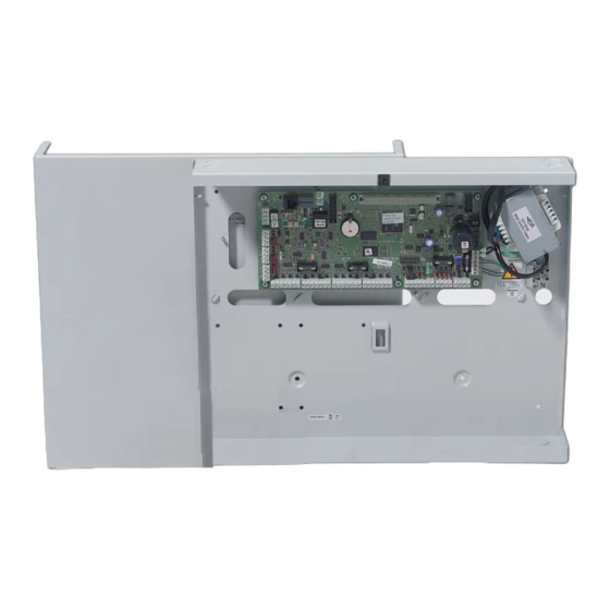
Setup
In order to get the system up and running, mount the panel
and connect and address all peripherals as described
below, before finally powering the system.
Peripheral Wiring
The following peripherals can be connected to the panel:
All bus lines: Mk7 LCD Keypad/Keyprox; TouchCenter;
3
MAX
; DCM; RIO; PSU.
Bus line 1 only: Telecom; RS232; ISDN; Ethernet; Audio
Interface
NOTE: The system must be wired in a daisy-chain
configuration. Spur and star configurations must
not be used. The recommended cable used to
connect the RS485 (AB) line is twisted pair
screened cable (Belden 8723 equivalent).
Keypad/
Panel
Keyprox
+12V
+
GND
–
A
A
B
B
*Do not connect +12V terminals between panels and
remote power supplies
Panel
Telecom
+12V
+12V
GND
-
A
A
B
B
RS485 Peripheral Wiring
RS485
Zones
STD
Buses
Min/Max
users*
1
16/48
94
2
16/96
242
2
16/264
987
4
16/520
987
Touch
RIO &
PSU
Center
DCM
+
+
X*
–
–
0V
G
A
A
Y
B
B
RS232
ISDN
+12V
12V
–
GND
A
A
B
B
A full technical installation manual will be given to each
installer at the training session. Additional manuals can be
purchased from your distributor.
Additionally, the installation manual is available from the
Honeywell Security website:
www.honeywell.com/security
Peripheral Addressing
The address on most peripherals is set by either jumpers or
a rotary switch. These must be set before the system is
powered up. See the instructions with the peripheral for
details. The following table identifies the available
peripheral addresses:
Peripheral
Mk7 Keypad
MK7
Keyprox
TouchCenter
1
RIO/PSU
MAX/DCM
Reader
Telecom
RS232
ISDN
Ethernet
NOTES: 1. A single TouchCenter can be fitted to each bus line.
Mains Supply Wiring
This product is not suitable for installation, maintenance or
connection by the user. A competent, qualified engineer,
with for example NSI approval, must carry out installation
and maintenance.
Warning: A means of isolation from the mains supply
Audio
Interface
+12V
GND
A
B
Connect the wires to the mains terminal block in the panel
as follows:
•
•
Ethernet
•
+
-
A
B
1
VALID ADDRESSES
Line
GD-48
GD-96
1
0-2,B-F
0-2,B-F
2
-
0-2,B-F
3-4
-
-
1
0-2
0-2
2
-
0-3
3-4
-
-
1
0-2
0-2
2
-
0-3
3-4
-
-
2
1
2-5
2
-5
2
-
0-5
3-4
-
-
1
0-3
0-3
2
-
0-3
3-4
-
-
1
(E)
(E)
1
(D)
(D)
1
(C)
(C)
1
(B)
(B)
Peripheral Addresses
2. If RIO 2 on-board is set to line 0 (dip sw 8) then the first
external RIO can use address 1 to give an extra 8 zones where
needed.
must be provided within two metres of the
control panel. Where live and neutral
supplies can be identified, a fused spur with
a 3A fuse must be fitted on the live circuit.
Where live and neutral circuits cannot be
readily identified, 3A fuses must be fitted to
both circuits.
Blue (neutral) – connect to terminal N
Green/Yellow (earth) – connect to terminal E
Brown (live) – connect to terminal L
GD-264
GD-520
0-2,B-F
0-2,B-F
0-6,F
0-6,F
-
0-6,F
0-2
0-2
0-3
0-6
-
0-6
0-2
0-2
0-3
0-6
-
0-6
2
2
2
-9, A-F
2
-9 & A-F
0-9, A-F
0-9 & A-F
-
0-9 & A-F
0-3
0-7
0-3
0-7
-
0-7
(E)
(E)
(D)
(D)
(C)
(C)
(B)
(B)

Related Manuals for Honeywell Galaxy Dimension GD Sereis


Summary of Contents for Honeywell Galaxy Dimension GD Sereis
- Page 1 Additional manuals can be training. This training is supplied free of charge and can be purchased from your distributor. arranged by contacting Honeywell Security. Additionally, the installation manual is available from the Honeywell Security website: www.honeywell.com/security...
-
Page 2: Operation
Zones Outputs Zones are the individual input circuits on Galaxy systems Galaxy outputs are addressed in the same way as the and are fully programmable in menu 52=Zones. zones. However, there are only 4 outputs on each RIO. The on-board outputs are on RIO 0 and RIO 1. The addresses are 1001 to 1004 (RIO 0) and 1011 to 1014 Zone Address Format (RIO 1). - Page 3 The ent key is used to enter a PIN code and to accept If a user is unable to restore an alarm, then a manager or screen information. engineer will have to be called, according to the indication The esc key is used to cancel or exit from the current given on the keypad.
-
Page 4: Remote Servicing
51=Parameters Note: Signalling via the on-board Telecom module will In this menu, all the general parameters are set up, such as meet EN50131/PD6662 Grade 2 requirements Bell time, entry/exit time, reset levels, and part set only. It should not be used for alarm signalling to signalling parameters. -
Page 5: Panel Specifications
Access Control Panel Specifications Door Control Modules (DCMs) can be added onto the Mechanical Galaxy bus lines to add fully integrated access control. Each DCM allows two Wiegand readers to be connected to All variants control two separate doors or one door with an entry and Enclosure exit reader. -
Page 6: Compliance And Approvals
HONEYWELL SECURITY LIMITED WARRANTY Compliance and Approvals Honeywell Security, and its divisions, subsidiaries and affiliates This product has been independently tested and certified by (“Seller”), 165 Eileen Way, Syosset, New York, 11791, warrants its CNPP to EN50131-3. products to be in conformance with its own plans and specifications and to be free from defects in materials and workmanship under normal use and service for 24 months from the date stamp control on the product.