
Related Manuals for YASKAWA GA800 600 V Drive


Summary of Contents for YASKAWA GA800 600 V Drive
- Page 1 GA800 600 V Drive AC Drive for Industrial Applications Installation & Primary Operation Catalog Code: GA80U5xxxxxxx 600 V class: 400 to 500 HP ND...
- Page 2 This Page Intentionally Blank YASKAWA TOEPC7106170VA GA800 600 V Drive Installation & Primary Operation...
-
Page 3: Table Of Contents
9. LED Status Ring ..........32 YASKAWA TOEPC7106170VA GA800 600 V Drive Installation & Primary Operation... - Page 4 Safe Disable Specifications ........... . 61 YASKAWA TOEPC7106170VA GA800 600 V Drive Installation & Primary Operation...
- Page 5 Revision History ........... . . 84 YASKAWA TOEPC7106170VA GA800 600 V Drive Installation & Primary Operation...
-
Page 6: General Information
Electrical Shock Hazard. Do not modify the drive body or drive circuitry. Modifications to drive body and circuitry can cause serious injury or death, will cause damage to the drive, and will void the warranty. Yaskawa is not responsible for modifications of the product made by the user. - Page 7 Then check the wiring and peripheral device ratings to find the cause of the problem. If you do not know the cause of the problem, contact Yaskawa before you energize the drive or peripheral devices. If you do not fix the problem before you operate the drive or peripheral devices, it can cause serious injury or death.
-
Page 8: Exclusion Of Liability
• This product is not designed and manufactured for use in life-support machines or systems. • Contact a Yaskawa representative or your Yaskawa sales representative if you are considering the application of this product for special purposes, such as machines or systems used for passenger cars, medicine, airplanes and aerospace, nuclear power, electric power, or undersea relaying. -
Page 9: How To Read The Catalog Code
Input power supply voltage • 5: Three-Phase AC 600 V Rated output current Note: Refer to the rated output current list for more information. EMC noise filter A: No built-in EMC filter YASKAWA TOEPC7106170VA GA800 600 V Drive Installation & Primary Operation... -
Page 10: Rated Output Current
Main speed frequency reference: -10 Vdc to +10 Vdc (20 kΩ), 0 Vdc to 10 Vdc (20 kΩ), 4 mA to 20 mA (250 Ω), 0 mA to 20 mA (250 Ω) Frequency Setting Signal Main speed reference: Pulse train input (maximum 32 kHz) YASKAWA TOEPC7106170VA GA800 600 V Drive Installation & Primary Operation... - Page 11 600 V class: Stops when the DC bus voltage is more than approximately 1040 V Protection Undervoltage 600 V class: Stops when the DC bus voltage decreases to less than approximately 460 V Protection YASKAWA TOEPC7106170VA GA800 600 V Drive Installation & Primary Operation...
- Page 12 Vibration • 20 Hz to 55 Hz: 5382 to 5472: 0.2 G (2.0 m/s , 6.56 ft/s Installation Install the drive vertically for sufficient airflow to cool the drive. Orientation YASKAWA TOEPC7106170VA GA800 600 V Drive Installation & Primary Operation...
-
Page 13: Area Of Use
For dimensions and installation instructions for other external heatsink installations, refer to the External Heatsink Installation Kit Instruction Manual (document number TOEPC72060003). For product weights, refer to the drive nameplate. YASKAWA TOEPC7106170VA GA800 600 V Drive Installation & Primary Operation... -
Page 14: Moving The Drive
Installation Position and Distance Install the drive vertically for sufficient airflow to cool the drive. Note: Contact Yaskawa or a Yaskawa representative for more information about installing drive models on their side. A - Vertical installation B - Horizontal installation Figure 6.1 Installation Position... -
Page 15: Removing/Reattaching Covers
A - Keypad C - Connector holder B - Keypad connector Figure 6.3 Remove the Terminal Cover, Keypad, and Keypad Connector YASKAWA TOEPC7106170VA GA800 600 V Drive Installation & Primary Operation... - Page 16 Reattach the Front Cover Wire the drive and other peripheral devices then reattach the front cover. Note: Wire the grounding terminals first, main circuit terminals next, and control circuit terminals last. YASKAWA TOEPC7106170VA GA800 600 V Drive Installation & Primary Operation...
- Page 17 Crush Hazard. Loosen the cover screws. Do not fully remove them. If you fully remove the cover screws, the terminal cover can fall and cause moderate injury. Figure 6.9 Loosen the Terminal Cover Mounting Screws YASKAWA TOEPC7106170VA GA800 600 V Drive Installation & Primary Operation...
-
Page 18: Electrical Installation
Sudden Movement Hazard. Correctly wire the start/stop and safety circuits before you energize the drive. If you momentarily close a digital input terminal, it can start a drive that is programmed for 3-Wire control and cause serious injury or death from moving equipment. YASKAWA TOEPC7106170VA GA800 600 V Drive Installation & Primary Operation... - Page 19 Motor winding and insulation failure can occur. NOTICE Do not connect the AC control circuit ground to the drive enclosure. Incorrect ground wiring can cause the control circuit to operate incorrectly. YASKAWA TOEPC7106170VA GA800 600 V Drive Installation & Primary Operation...
- Page 20 FM AM Pulse train input 0 - 10 V 2 kΩ 4 mA to 20 mA 0 - 10 V MFAI 3/PTC input E (G) Figure 7.1 Standard Drive Connection Diagram YASKAWA TOEPC7106170VA GA800 600 V Drive Installation & Primary Operation...
- Page 21 A junction terminal is necessary to connect wires that are less than the applicable gauge to the drive. Contact Yaskawa or your nearest sales representative for more information about selection and installation of the junction terminal.
-
Page 22: Main Circuit Terminal Functions
Electrical Shock Hazard. Do not connect terminals R/L1, S/L2, T/L3, U/T1, V/T2, W/T3, -, +1, +2, +3, B1, or B2 to the ground terminal. If you connect these terminals to earth ground, it can cause damage to the drive or serious injury or death. YASKAWA TOEPC7106170VA GA800 600 V Drive Installation & Primary Operation... -
Page 23: Main Circuit Terminal Block Wiring
× wire resistance (Ω/km) × wiring distance (m) × motor rated current (A) × 10 Precautions during Wiring • Refer to “Yaskawa AC Drive Option Braking Unit, Braking Resistor Unit Instruction Manual (TOBPC72060001)” for information about wire gauges and tightening torques to connect braking resistor units or braking units. -
Page 24: Main Circuit Terminal Block Wiring Procedure
The procedures to wire the main circuit terminal block are different for different drive models. Refer to Table 7.2 procedures by drive model. YASKAWA TOEPC7106170VA GA800 600 V Drive Installation & Primary Operation... -
Page 25: Wiring The Main Circuit Terminal Block Using Procedure B
• After you connect the wire to the terminal, do not twist or move it too much. • Be sure to use only wires with the correct size, stripped wire length, and tightening torque as specified by Yaskawa. • Use tools that fit the shape of the screw head to tighten and loosen the terminal block screws. - Page 26 • Remove sharp edges from the wiring cover cutaway section to prevent damage to the wires. • If you use the wiring cover correctly, but you use wires that are not specified by Yaskawa, the drive will not necessarily keep its IP20 protective level.
-
Page 27: Keypad: Names And Functions
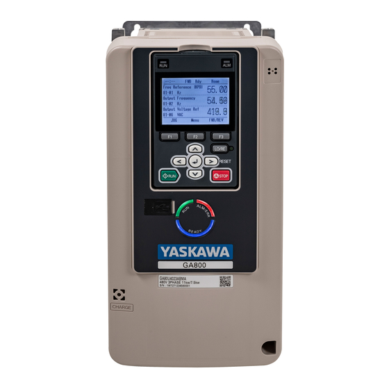
Attach the wiring cover and terminal block cover to their initial positions and tighten the screws on the terminal block cover. Figure 7.8 Reattach the Wiring Cover Put the terminal cover back in its initial position. Keypad: Names and Functions Figure 8.1 Keypad YASKAWA TOEPC7106170VA GA800 600 V Drive Installation & Primary Operation... - Page 28 Insertion point for a mini USB cable. Uses a USB cable (USB standard 2.0, type A - mini-B) to connect the keypad to a PC. Connects to the drive using an RJ-45 8-pin straight through UTP CAT5e extension cable or keypad connector. RJ-45 Connector YASKAWA TOEPC7106170VA GA800 600 V Drive Installation & Primary Operation...
- Page 29 Accept Existing RUN Command], the drive can start suddenly. Before you change the control source, remove all personnel from the area around the drive, motor, and load. Sudden starts can cause serious injury or death. YASKAWA TOEPC7106170VA GA800 600 V Drive Installation & Primary Operation...
-
Page 30: Keypad Mode And Menu Displays
8 Keypad: Names and Functions ◆ Keypad Mode and Menu Displays Figure 8.2 Keypad Functions and Display Levels YASKAWA TOEPC7106170VA GA800 600 V Drive Installation & Primary Operation... - Page 31 Saves parameters to the keypad as backup. Parameter Backup/Restore Shows modified parameters and fault history. Programming Mode Modified Parameters/Fault Log Auto-Tunes the drive. Auto-Tuning Changes initial settings. Initial Setup Diagnostic Tools Sets data logs and backlight. YASKAWA TOEPC7106170VA GA800 600 V Drive Installation & Primary Operation...
-
Page 32: Led Status Ring
• The drive is set to coast-to-stop with timer (b1-03 = 3 [Stopping Method Selection = Coast to Stop with Timer]), and the Run command is disabled then enabled during the Run wait time. The motor is stopped. Refer to Figure 9.1 for the difference between “flashing” and “flashing quickly”. YASKAWA TOEPC7106170VA GA800 600 V Drive Installation & Primary Operation... -
Page 33: Drive Start-Up Procedure
Refer to the motor nameplate and record the information in this table before you energize the drive. Item Value The motor Rated Power Motor Rated Voltage Motor Rated Current (FLA) Motor Rated Frequency Motor Maximum Frequency Motor Pole Count Number of Motor Poles YASKAWA TOEPC7106170VA GA800 600 V Drive Installation & Primary Operation... -
Page 34: Change Parameter Setting Values
• When the drive is in HOME Mode, the screen shows [Home] in the upper right-hand corner of the screen. • If [Home] is not shown above the , push (Back). Push (Menu). YASKAWA TOEPC7106170VA GA800 600 V Drive Installation & Primary Operation... - Page 35 [Min/Max] to show the minimum value or the maximum value on the display. Push to keep the changes. Continue to change parameters, then push [Back], [Home] to go back to the home screen after you change all the applicable parameters. YASKAWA TOEPC7106170VA GA800 600 V Drive Installation & Primary Operation...
-
Page 36: Disable The Initial Setup Screen
Damage to Equipment. Do not energize and de-energize the drive more frequently than one time each 30 minutes. If you frequently energize and de-energize the drive, it can cause drive failure. YASKAWA TOEPC7106170VA GA800 600 V Drive Installation & Primary Operation... -
Page 37: Input Terminals
• PTC input (Motor Overheat Protection) Set DIP switch S4 to “PTC” and set DIP switch S1-3 to “V” to set terminal A3 for PTC input. Frequency reference common E (G) Connecting shielded cable YASKAWA TOEPC7106170VA GA800 600 V Drive Installation & Primary Operation... -
Page 38: Output Terminals
(Zero Speed) Note: Do not set functions that frequently switch ON/OFF to MFDO (M1 to M6) because this will decrease the performance life of the relay contacts. Yaskawa estimates switching life at MFDO 200,000 times (assumes 1 A, resistive load). -
Page 39: Control Circuit Wire Gauges And Tightening Torques
Use the tables in this section to select the correct wires. Use shielded wire to wire the control circuit terminal block. Use crimp ferrules on the wire ends to make the wiring procedure easier and more reliable. YASKAWA TOEPC7106170VA GA800 600 V Drive Installation & Primary Operation... -
Page 40: Wiring The Control Circuit Terminal
• Connect the shield of shielded cable to the applicable ground terminal. Incorrect equipment grounding can cause drive or equipment malfunction from electrical interference. Correctly ground the drive terminals and complete main circuit wiring before you wire the control circuit. Remove the keypad and front cover. YASKAWA TOEPC7106170VA GA800 600 V Drive Installation & Primary Operation... - Page 41 Figure 10.6 Remove the LED Status Ring Board A - Drive front C - Temporary placement holes B - LED status ring board Figure 10.7 Remove the LED Status Ring Board YASKAWA TOEPC7106170VA GA800 600 V Drive Installation & Primary Operation...
- Page 42 A - Connect the shield to terminal E (G) of the drive. C - Insulate with electrical tape or shrink tubing. B - Sheath Figure 10.9 Prepare the Ends of Shielded Wire YASKAWA TOEPC7106170VA GA800 600 V Drive Installation & Primary Operation...
-
Page 43: Switches And Jumpers On The Terminal Board
• MFDI (terminals S1 to S8) • Pulse train output (terminal MP) • MFAI (terminals A1 to A3) • PTC input (terminal A3) • MFAO (terminals FM, AM) • MEMOBUS/Modbus communications (terminals D+, D-, AC) YASKAWA TOEPC7106170VA GA800 600 V Drive Installation & Primary Operation... -
Page 44: Pulse Train Output
NOTICE Damage to Equipment. Do not close the circuit between terminals SP-SN. If you close the circuits terminals SC- SP and terminals SC-SN, it will cause damage to the drive. YASKAWA TOEPC7106170VA GA800 600 V Drive Installation & Primary Operation... -
Page 45: Set Input Signals For Mfai Terminals A1 To A3
1: -10 V to +10 V/-100% to 100% (input impedance: 20 kΩ) S1-3 H3-05 2: 4 mA to 20 mA/0% to 100% (input impedance: 250 Ω) Current input 3: 0 mA to 20 mA/0% to 100% (input impedance: 250 Ω) YASKAWA TOEPC7106170VA GA800 600 V Drive Installation & Primary Operation... -
Page 46: Set Mfai Terminal A3 To Ptc Input
Set the signal type for terminals AM and FM to voltage or current output. Use jumper switch S5 and H4-07, H4-08 [Terminal FM Signal Level Select, Terminal AM Signal Level Select] to set the signal type. Figure 10.16 Location of Jumper Switch S5 YASKAWA TOEPC7106170VA GA800 600 V Drive Installation & Primary Operation... -
Page 47: Switch On Termination Resistor For Memobus/Modbus Communications
• General variable-speed. Best method to operate more than one motor from one drive. • When motor parameters are not available. • General variable-speed • High precision and high speed response without speed feedback (Default) YASKAWA TOEPC7106170VA GA800 600 V Drive Installation & Primary Operation... -
Page 48: Drive Duty Modes
Select this tuning mode when: • The drive and motor capacities are different. Stationary Line-Line Resistance • The drive is in V/f Control. • You have replaced the drive and motor. YASKAWA TOEPC7106170VA GA800 600 V Drive Installation & Primary Operation... -
Page 49: Drive Parameters
AOLV b1-02 Run Command Selection 1 (0181) Sets the input method for the Run command. 0 : Keypad 1 : Analog Input 2 : Memobus/Modbus Communications 3 : Option PCB YASKAWA TOEPC7106170VA GA800 600 V Drive Installation & Primary Operation... - Page 50 E1-04 Maximum Output Frequency (0303) Sets the maximum output frequency for the V/f pattern. CL-V/f AOLV E1-05 Maximum Output Voltage (0304) Sets the maximum output voltage for the V/f pattern. YASKAWA TOEPC7106170VA GA800 600 V Drive Installation & Primary Operation...
- Page 51 Terminal A2 Function Selection (0418) Sets the function for MFAI terminal A2. CL-V/f AOLV H3-11 Terminal A2 Gain Setting (0419) Sets the gain of the analog signal input to MFAI terminal A2. YASKAWA TOEPC7106170VA GA800 600 V Drive Installation & Primary Operation...
- Page 52 Motor Overload Protection Time (0481) Sets the operation time for the electronic thermal protector of the drive to prevent damage to the motor. Usually it is not necessary to change this setting. YASKAWA TOEPC7106170VA GA800 600 V Drive Installation & Primary Operation...
-
Page 53: Ul Standards
Comply with local standards for correct wire gauges in the region where the drive is used. WARNING Electrical Shock Hazard. Only connect peripheral options, for example a braking resistor, to terminals +1, +3, and -. Incorrect wiring can cause serious injury or death. YASKAWA TOEPC7106170VA GA800 600 V Drive Installation & Primary Operation... -
Page 54: Closed-Loop Crimp Terminals
• Refer to the instruction manual for each device for recommended wire gauges to connect peripheral devices or options to terminals +1, +3, and -. Contact Yaskawa or your nearest sales representative if the recommended wire gauges for the peripheral devices or options are out of the range of the applicable gauges for the drive. -
Page 55: 600 V Class
Then check the wiring and peripheral device ratings to find the cause of the problem. If you do not know the cause of the problem, contact Yaskawa before you energize the drive or peripheral devices. If you do not fix the problem before you operate the drive or peripheral devices, it can cause serious injury or death. -
Page 56: E2-01: Motor Rated Current (Fla)
L1-01 =0 [Motor Overload (oL1) Protection = Disabled] and install thermal overload relays for each motor. The electronic thermal protection of the drive will not function and it can cause damage to the motor. YASKAWA TOEPC7106170VA GA800 600 V Drive Installation & Primary Operation... - Page 57 Use this setting for vector motors with a speed range for constant torque of 1:100. The speed control for this motor is 1% to 100% when at 100% load. Operating slower than 1% speed at 100% load will cause motor overload. YASKAWA TOEPC7106170VA GA800 600 V Drive Installation & Primary Operation...
-
Page 58: L1-02: Motor Overload Protection Time
This example shows a general-purpose motor operating at the base frequency with L1-02 set to 1.0 min. • Cold start Shows the motor protection operation time characteristics when the overload occurs immediately after starting operation from a complete stop. • Hot start YASKAWA TOEPC7106170VA GA800 600 V Drive Installation & Primary Operation... -
Page 59: L1-03: Motor Thermistor Oh Alarm Select
2 : Fast Stop (Use C1-09) The drive stops the motor in the deceleration time set in C1-09 [Fast Stop Time]. Fault relay output terminal MA-MC turns ON, and MB-MC turns OFF. YASKAWA TOEPC7106170VA GA800 600 V Drive Installation & Primary Operation... -
Page 60: China Rohs Compliance
This product complies with EU RoHS directives. In this table, "×" indicates that hazardous substances that are exempt from EU RoHS directives are contained. 对应中国RoHS指令 图 14.1 中国RoHS标志 中国RoHS标志依据2016年1月26日公布的《电器电子产品有害物质限制使用管理办法》,以及《电子电气产品有害物 质限制使用标识要求》(SJ/T 11364-2014)作成。电子电气产品中特定6种有害物质的含量超过规定值时,应标识此标 志。中间的数字为在中国生产销售以及进口的电子电气产品的环保使用期限(年限)。电子电气产品的环保使用期限从 生产日期算起。在期限内,正常使用产品的过程中,不会有特定的6种有害物质外泄进而对环境、人和财产造成深刻影 响。 本产品的环保使用期限为15年。但需要注意的是环保使用期限并非产品的质量保证期限。 YASKAWA TOEPC7106170VA GA800 600 V Drive Installation & Primary Operation... -
Page 61: 本产品中含有有害物质的信息
Incorrect application of the Safe Disable function can cause serious injury or death. YASKAWA TOEPC7106170VA GA800 600 V Drive Installation & Primary Operation... -
Page 62: Using The Safe Disable Function
Set the EDM function to one of the MFDO terminals [H2-xx = 21 or 121] to monitor the status of the Safe Disable function. This is the “Safe Disable monitor output function”. YASKAWA TOEPC7106170VA GA800 600 V Drive Installation & Primary Operation... -
Page 63: Enabling And Disabling The Drive Output ("Safe Torque Off")
H1 and H2 to hold for at least 2 ms. The drive may not be able to switch to the “Safe Torque Off” status if terminals H1 and H2 are only open for less than 2 ms. YASKAWA TOEPC7106170VA GA800 600 V Drive Installation & Primary Operation... -
Page 64: Safe Disable Monitor Output Function And Keypad Display
Table 15.2. If one or more of the these items are true, the ON/OFF status of the MFDO may not display correctly on the keypad: • Incorrect parameter settings. YASKAWA TOEPC7106170VA GA800 600 V Drive Installation & Primary Operation... -
Page 65: Disposal Instructions
• Customers are responsible for microSD card data protection. PC functions that format and delete the data may not be sufficient to fully erase the microSD card data. Yaskawa recommends that customers physically destroy the microSD card in a shredder or use data wipe software to fully erase the card. ◆... -
Page 66: Troubleshooting
Modbus Communication Error There is a short circuit in the communications cable • Repair short circuits and connect cables. or the communications cable is not connected. • Replace the defective communications cable. YASKAWA TOEPC7106170VA GA800 600 V Drive Installation & Primary Operation... - Page 67 MFDI terminal S5 caused an external fault through an Find the device that caused the external fault and remove the external device. cause. Clear the external fault input in the MFDI. YASKAWA TOEPC7106170VA GA800 600 V Drive Installation & Primary Operation...
- Page 68 U/T1, V/T2, and W/T3. Make sure that there is not a drive. short circuit in terminals - and terminals U/T1, V/T2, and W/T3. • If there is a short circuit, contact Yaskawa or your nearest sales representative. The acceleration time is too short.
- Page 69 The option card connected to connector CN5-B was De-energize the drive. oFb01 Option Fault/Connection Error changed during operation. Refer to the option card manual and correctly connect the option card to the connector on the drive. YASKAWA TOEPC7106170VA GA800 600 V Drive Installation & Primary Operation...
- Page 70 • Examine the acceleration/deceleration times and the motor start/ The acceleration/deceleration times or cycle times are too short. stop frequencies (cycle times). • Increase the values set in C1-01 to C1-08 [Acceleration/ Deceleration Times]. YASKAWA TOEPC7106170VA GA800 600 V Drive Installation & Primary Operation...
- Page 71 • Examine the settings for all speed search-related parameters. The speed search-related parameters are set incorrectly. • Adjust b3-03 [Speed Search Deceleration Time]. • Set b3-24 = 1 [Speed Search Method Selection = Speed Estimation] after Auto-Tuning. YASKAWA TOEPC7106170VA GA800 600 V Drive Installation & Primary Operation...
- Page 72 • Make sure that a magnetic contactor is not the source of the electrical interference, then use a Surge Protective Device if necessary. YASKAWA TOEPC7106170VA GA800 600 V Drive Installation & Primary Operation...
- Page 73 Zero Servo Fault There is a battery in the keypad, but the date and time Use the keypad to set the date and time. Keypad Time Not Set are not set. YASKAWA TOEPC7106170VA GA800 600 V Drive Installation & Primary Operation...
-
Page 74: Minor Faults/Alarms
Modbus Communication Error • Repair short circuits and connect cables. There is a short circuit in the communications cable or the communications cable is not connected. • Replace the defective communications cable. YASKAWA TOEPC7106170VA GA800 600 V Drive Installation & Primary Operation... - Page 75 Correctly connect the signal line to MFDI terminal S2. External Fault [H1-02 = 2C to 2F] is set to MFDI Correctly set the MFDI. terminal S2, but the terminal is not in use. YASKAWA TOEPC7106170VA GA800 600 V Drive Installation & Primary Operation...
- Page 76 • Examine the external 24 V power supply for problems. There is not a micro SD card in the keypad. Put a micro SD card in the keypad. Com Error / Abnormal SD card YASKAWA TOEPC7106170VA GA800 600 V Drive Installation & Primary Operation...
- Page 77 • Examine the input power for problems. • Make the drive input power stable. • If the input power supply is good, examine the magnetic contactor on the main circuit side for problems. YASKAWA TOEPC7106170VA GA800 600 V Drive Installation & Primary Operation...
-
Page 78: Parameter Setting Errors
• When the Safe Disable function is not in use, use a jumper to connect terminals H1-HC and H2-HC. There is internal damage to the two Safe Disable Replace the board or the drive. Contact Yaskawa or your nearest channels. sales representative to replace the board. - Page 79 • For motor 2: E3-09 ≤ E3-07 < E3-06 ≤ E3-11 ≤ E3-04 [Minimum Output Frequency ≤ Mid Point A Frequency < Base Frequency ≤ Mid Point B Frequency ≤ Maximum Output Frequency] YASKAWA TOEPC7106170VA GA800 600 V Drive Installation & Primary Operation...
-
Page 80: Auto-Tuning Errors
You can use the drive in the application if you cannot find the cause of the Endx error. Erx identifies that Auto-Tuning was not successful. Find and repair the cause of the error and do Auto-Tuning again. YASKAWA TOEPC7106170VA GA800 600 V Drive Installation & Primary Operation... - Page 81 First, decrease the test signal amplitude, and then do Inertia Tuning. If the error continues, decrease the test signal frequency and do Inertia Tuning again. YASKAWA TOEPC7106170VA GA800 600 V Drive Installation & Primary Operation...
-
Page 82: Backup Function Operating Mode Display And Errors
The parameters are not stored in the keypad. Connect a keypad that has the correct parameters. Restore the parameters. The password set in the backup operation with qx-xx Set the DWEZ PC software password supplied by Yaskawa for the PWEr DWEZ Password Mismatch [DriveWorksEZ Parameters] and rx-xx DWEZ program user ID downloaded to the drive. - Page 83 The parameters that are backed up in the keypad and Restore or backup the parameter again. vFyE Parameters do not Match the parameters in the drive do not align. Verify the parameters. YASKAWA TOEPC7106170VA GA800 600 V Drive Installation & Primary Operation...
-
Page 84: Revision History
Revision History Date of Revision Section Revised Content Publication Number – – May 2020 First Edition YASKAWA TOEPC7106170VA GA800 600 V Drive Installation & Primary Operation... - Page 85 YASKAWA TOEPC7106170VA GA800 600 V Drive Installation & Primary Operation...
- Page 86 GA800 600 V Drive Installation & Primary Operation YASKAWA AMERICA, INC. YASKAWA EUROPE GmbH YASKAWA ELÉTRICO DO BRASIL 2121, Norman Drive South, Waukegan, IL Hauptstraβe 185, 65760 Eschborn, LTDA. 60085, U.S.A. Germany 777, Avenida Piraporinha, Diadema, São +1-800-YASKAWA (927-5292) Phone: +49-6196-569-300 Paulo, 09950-000, Brasil www.yaskawa.com...