Emerson Copeland 4MF-13X User Manual
Semi-hermetic compressor stream for refrigeration applications
Hide thumbs
Also See for Copeland 4MF-13X:
- Application manuallines (28 pages) ,
- Application manuallines (44 pages)

Related Manuals for Emerson Copeland 4MF-13X


Summary of Contents for Emerson Copeland 4MF-13X
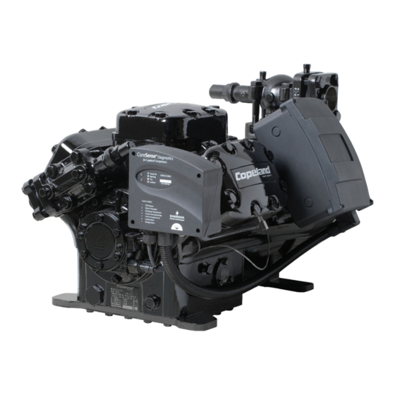
- Page 1 Copeland Semi-Hermetic Compressor ™ Stream for refrigeration applications User Manual...
-
Page 2: Appendix
With scrolls and semi-hermetic ™ compressors available for all main refrigerants, equipped with smart electronics and capable of modulation, Emerson Climate Technologies has taken compressor technology to new heights. -
Page 3: Table Of Contents
Table of Contents Safety Information Product Description Design Features Nomenclature Operating Envelopes Nameplate Information Application Range Installation Guidelines Electrical Connection Wiring Diagrams Start-up Leak Checking, Evacuation and Charging Maintenance Appendices Appendix 1 Appendix 2 Appendix 3 Appendix 4 Notes General Information Contact List... -
Page 4: Safety Information
Safety Information • Copeland brand products semi-hermetic compressors are manufactured according to the latest European safety standards. ™ Particular emphasis has been placed on the user’s safety. • These compressors are intended for installation in systems according to the EC Machines directive. They may be put to service only if they have been installed in these systems according to instructions and conforming with the corresponding provisions of legislation. -
Page 5: Product Description
Product Description Technical Data Compressor 4MF-13X 4MA-22X 4ML-15X 4MH-25X 4MM-20X 4MI-30X 4MT-22X 4MJ-33X Number of Cylinders 50 Hz 61.7 61.7 71.4 71.4 78.2 78.2 87.7 87.7 Displacement /hr) 60 Hz 74.5 74.5 86.2 86.2 94.4 94.4 105.9 105.9 Bore/Stroke (mm) 63.5/56.0 63.5/56.0 68.3/56.0... -
Page 6: Design Features
Design Features Compressor Structure All compressors are fitted with Stream valve plates which cannot be dismantled. To maintain the high capacity of these compressors the correct valve-plate-to-body gasket must always be selected in case of exchange. Each cylinder head has 2 plugged 1/8” - 27NPTF tapped holes for connecting high-pressure switches. -
Page 7: Nomenclature
Oil Circulation Oil returns with the suction gases through a suction strainer and separates in the motor chamber reaching the crankcase by way of oil return relief valve in the partition between motor housing and crankcase. This relief valve closes on compressor start-up due to the pressure difference arising between motor side and crankcase, thus, slowing down pressure decrease in the crankcase over a certain period of time. -
Page 8: Operating Envelopes
Operating Envelopes 4MF1-13X, 4ML1-15X, 4MM1-20X, 4MT1-22X 4MA1-22X, 4MH1-25X, 4MI1-30X, 4MJ1-33X, 4MK1-35X 6MM1-30X, 6MT1-35X, 6MU1-40X 6MI1-40X, 6MJ1-45X, 6MK1-50X R404A R404A -50 -45 -40 -35 -30 -25 -20 -15 -10 -45 -40 -35 -30 -25 -20 -15 -10 -5 Evaporating Temperature °C Evaporating Temperature °C 20K Suction Superheat 0°C Return Gas Temperature... - Page 9 4MF1-13X, 4ML1-15X 4MA1-22X, 4MH1-25X 4MM1-20X, 4MT1-22X, 4MU1-25X 4MI1-30X, 4MJ1-33X, 4MK1-35X 6MM1-30X, 6MT1-35X, 6MU1-40X 6MI1-40X, 6MJ1-45X, 6MK1-50X R134a R134a -20 -15 -10 -5 15 20 Evaporating Temperature °C Evaporating Temperature °C 25°C Return Gas Temperature 20K Suction Superheat...
- Page 10 4MF1-130, 4ML1-150, 4MM1-200, 4MT1-220, 4MA1-220, 4MH1-250, 4MI1-300, 4MJ1-330 4MU1-250, 6MM1-300, 6MT1-350, 6MU1-400 -25 -20 -15 -55 -50 -45 -40 -35 -30 -25 -20 -15 -10 Evaporating Temperature °C Evaporating Temperature °C 20°C Suction Gas Return+Fan+Liquid Injection 20°C Return Gas Temperature+Fan+Demand Cooling 20K Suction Superheat+Fan 20K Suction Superheat 20°C Return Gas Temperature...
-
Page 11: Nameplate Information
Nameplate Information All important information for identification of the compressor is printed on the nameplate located below the compressor oil pump. The type of refrigerant used should be stamped on the nameplate by the installer. Figure 3 The date of production indicates the year and week of production. The year and month of production are also part of the serial number (Jan. -
Page 12: Installation Guidelines
Installation Guidelines WARNING High pressure! Injury to skin and eyes, possible! Be careful when opening connections on a pressurized item. Compressor Handling Delivery Please check whether the delivery is correct and complete. Any deficiency should be reported immediately in writing. •... - Page 13 Installation Location Ensure the compressors are installed on a solid level base. Mounting Parts To minimize vibration and start/stop impulses, flexible mounting should be used. For this purpose, one set of spring mounting parts for each of the Stream models is delivered with each 4M* and 6M* compressor. Due to differences in weight (cylinder/motor side), different springs have to be used on both sides.
- Page 14 Pressure Safety Controls High-pressure Control A high-pressure control with a maximum cut-out setting of 28 bar(g) is required. The high-pressure cut-out should have a manual reset feature for the highest level of system protection. Low-Pressure Control The normal minimum cut-out setting is 0.1 bar(g) for R404A. The low-pressure cut-out should have a manual reset feature for the highest level of system protection.
-
Page 15: Electrical Connection
Screens CAUTION Screen blocking! Compressor breakdown! Use screens with at least 0.6 mm openings. The use of screens finer than 30 x 30 mesh (0.6 mm openings) anywhere in the system should be avoided with these compressors. Field experience has shown that finer mesh screens used to protect thermal expansion valves, capillary tubes or accumulators can become temporarily or permanently plugged with normal system debris and block the flow of either oil or refrigerant to the compressor. -
Page 16: Wiring Diagrams
Wiring Diagrams The position of the jumpers in the terminal box and the recommended wiring diagrams are shown in Figures 9 and 10. Wiring Diagram for Part Winding Motors (AW---) Part winding motors can be connected direct-on-line or part-winding start. Part-winding start Direct-on-line start First start step 1-2-3... - Page 17 Wiring diagram for Star / Delta motors (EW---) Star / Delta motors can be connected direct-on-line or Star / Delta start. Direct-on-line start Direct-on-line start Star / Delta start Δ Y - Δ Star / Delta motor Y - Δ 1(U) 2(V) 3(W)
- Page 18 Protection Devices Independently from the internal motor protection, fuses must be installed before the compressor. The selection of fuses has to be carried out according to VDE 0635, DIN 57635, IEC 269-1or EN 60-269-1. CoreSense Diagnostics ™ CoreSense™ Diagnostics for all 4M* and 6M* Stream semi-hermetic compressors combines oil and motor protection into one module, replacing OPS1/2 and the electronic module INT69TM.
- Page 19 For the electrical connection of the CoreSense™ Diagnostics module, please refer to wiring diagram below: 120v 240v T Stat Contactor Coil Alarm Indicator CoreSense Terminal Strip Figure 12: CoreSense Wiring Diagram ™ NOTE: For more information, please refer to Technical Information D7.8.4 “CoreSense™ Diagnostics for Stream refrigeration compressors”.
-
Page 20: Start-Up Leak Checking, Evacuation And Charging
Start-up Leak Checking, Evacuation, and Charging WARNING Diesel effect! Compressor destruction! The mixture of air and oil at high temperature can lead to an explosion. Avoid operating with air. Leak Test The suction shut-off valve and discharge shut-off valve on the compressor must remain closed during pressure testing to prevent air and moisture from entering the compressor. - Page 21 To avoid motor damage the compressor MUST NOT be started, nor may high-potential testing be carried out under vacuum. Minimum Run Time Emerson Climate Technologies recommends a maximum of 10 starts per hour. The most critical consideration is the minimum run time required to return oil to the compressor after start-up.
-
Page 22: Maintenance
POE to absorb sufficient moisture to make it unacceptable for use in a refrigeration system. Since POE holds moisture more readily than mineral oil it is more difficult to remove it through the use of vacuum. Compressors supplied by Emerson Climate Technologies contain oil with low moisture content, and it may rise during the system assembling process. - Page 23 Oil Additives Although Emerson Climate Technologies cannot comment on any specific product, from our own testing and past experience, we do not recommend the use of any additives to reduce compressor bearing losses or for any other purpose. Furthermore, the long term chemical stability of any additive in the presence of refrigerant, low and high temperatures, and materials commonly found in refrigeration systems is complex and difficult to evaluate without rigorously controlled chemical laboratory testing.
-
Page 24: Appendices
Appendices Appendix 1: Stream Compressor Connections 4M*Model 4MF-13X 4MA-22X 4ML-15X 4MH-25X 4MM-20X 4MI-30X 4MT-22X 4MJ-33X 4MU-25X 4MK-35X Suction line size (sweat) Discharge line size (sweat) 4MF13X, 4ML15X, 4MA22X, Ø 1 5/8" 4MF13X, 4ML15X, 4MA22X, Ø 1 1/8" 4MM20X, 4MH25X, 4MI30X 4MM20X, 4MH25X, 4MI30X Suction line size (sweat) Discharge line size (sweat) - Page 25 6M*Model 6MU-40X 6MK-50X 6MT-35X 6MJ-45X 6MI-40X 6MM-30X Suction line size (sweat) Discharge line size (sweat) Ø 2 1/8" Ø 1 5/8" 6MM30X, 6MT35X, 6MI40X, 6MJ45X 6MT35X, 6MU-40X, 6MJ45X, 6MK-50X Suction line size (sweat) Discharge line size (sweat) Ø 2 5/8" Ø...
- Page 26 Appendix 2: Tightening Torques in Nm 1/2”-13 UNC 1/2”-13 UNC Discharge 53 - 84 Nm 53 - 84 Nm shut-off valve SW 19 Suction SW 19 shut-off valve 5/8”-11 UNC 1 3/4”-12 UNF 104 - 164 Nm Rotalock nut 41 - 54 Nm SW 23.8 SW 50 3/8”-16 UNC...
- Page 27 Appendix 3: CoreSense Diagnostics for Copeland Stream Compressors Quick Installation ™ ™ Guide. 1. Remove CoreSense front module cover by unscrewing 4 screws in the corners. 2. Verify DIP-switch settings. Dip-switch DIP-switch meaning Default Comment Node address Change it only if communication with rack controller is used Node address Change it only if communication with pack controller is used Node address...
- Page 28 5. In case of direct-start connection, L2 power supply lead; in case of part winding connection, L2 and L8 power leads from the customer should go through the current sensor opening in the same direction. Current sensor opening 6. Make sure that the black lead from the sensor module is always connected to terminal 2 (factory-installed). The black lead from the sensor module must always be connected to that terminal off which the power supply cable is lead through current sensor.
-
Page 29: Appendix
Compressors in the higher capacity range need some form of capacity control to accommodate varying refrigeration load. The capacity control kit supplied by Emerson Climate Technologies will reduce the refrigeration capacity along with a similar proportional reduction in power Input. This ensures optimum performance even in part load. - Page 30 Retrofit Kit (Conversion Kit) A conversion kit for subsequent installation can also be delivered. The kit includes: 1 x cylinder head for capacity control 1 x valve plate and gasket kit 1 x solenoid valve assembly 2 x mounting screws Active Gasket Inactive Gasket Capacity Control Cylinder Head...
- Page 31 Capacity Control Position Capacity control must be fitted in the following positions: • 4M* 50% terminal box side • 6M* 1st step 33% upper cylinder head • 6M* 2nd step 66% terminal box side V.1.18.00 V.1.19.00 Capacity control position 4M* Capacity control position 6M* R404A Capacity Control Selection Table Remaining...
- Page 32 R404 Application Range Application envelope for High and Medium temperature 4M* and 6M* models with R404A Full Capacity (100%) Suction gas temperature = 0°C Full Capacity (100%) R404A Suction gas temperature = 25°C 1or 2 Capacity Controls + Fan Envelope limit (66%, 50%, 33%) 1 or 2 Capacity Controls without fan Envelope limit (66%, 50%, 33%) -45 -40...
-
Page 33: Notes
Notes... - Page 34 Notes...
-
Page 35: General Information
Products, specifications, and data in this literature are subject to change without notice. The information given herein is based on data and tests which Emerson Climate Technologies believes to be reliable and which are in accordance with today’s technical knowledge. It is intended for use by persons having the appropriate technical knowledge and skill, at their own discretion and risk. -
Page 36: Contact List
Scan With Your Asia 02 B02 10 – R01 Issued 08/2015– GSCAA050 Smartphone For Emerson and Copeland Scroll are trademarks of Emerson Electric Co. or one of its affiliated companies. More Information ©2014 Emerson Climate Technologies, Inc. All rights reserved.