
Related Manuals for Toshiba 48-1250 A

Summary of Contents for Toshiba 48-1250 A
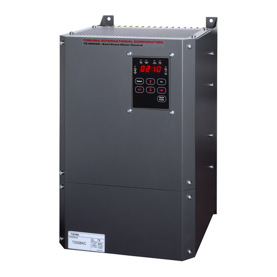
- Page 1 DOCUMENT: NBZ0001 INSTRUCTION MANUAL INSTALLATION - OPERATION - MAINTENANCE TD SERIES Low Voltage Digital Solid State Starter 48 - 1250 A Issued: 9/03 Manufactured in the USA...
- Page 3 SAFETY SAFETY CODES Toshiba motor control is designed and built in accordance with the latest applicable provisions of NEMA and the National Electrical Code. Installations must comply with all applicable state and local codes, adhere to all applicable National Electric Code (NFPA 70) standards and instructions provided in this manual.
- Page 4 SAFETY IMPORTANT MESSAGES Read this manual and follow its intructions. Signal words such as DANGER, WARNING and CAUTION will be followed by important safety information that must be carefully reviewed. Indicates a situation which will result in death, serious injury, and severe property damage if you DANGER do not follow instructions.
-
Page 5: Table Of Contents
Table of Contents TD Series Digital Solid State Soft Starter 48 - 1250A Chapter 1: Introduction ... 1 1.1 General 1.2 Specifications and Performance Features Chapter 2: Installation ... 4 2.1 Receiving and Unpacking 2.2 Location 2.3 Initial Unit Inspection 2.4 Warning 2.5 Mounting and Cleaning 2.6 Power Terminal Wire Range and Tightening Torque... -
Page 7: Digital Solid State Soft Starter
TD Series Chapter 1 - Introduction Digital Solid State Soft Starter 48 - 1250A 1.1 General The TD Series is a digitally programmable solid state reduced voltage soft starter. Its six SCR design features a voltage/current ramp with an anti-oscillation circuit for smooth load acceleration. The SCRs are sized to withstand starting currents of 500% for 60 seconds (compared to 350% for 30 seconds from other manufacturers). - Page 8 TD Series Digital Solid State Soft Starter 48 - 1250A 1.2 Specifications and Performance Features Cont’d Advanced Motor Protection Starting: Programmable for Class 5 through 30 Two Stage Electronic Run: Programmable for Class 5 through 30 when "At-Speed" Overload Curves is detected.
- Page 9 TD Series Digital Solid State Soft Starter 48 - 1250A 1.2 Specifications and Performance Features Cont’d Metering Functions Phase Currents 0 - 9999 Amps, Phase A, B, or C Remaining Thermal Capacity 0 - 100% of available motor thermal capacity Elapsed Time 0 - 1,000,000.0 hours, non resetable Run Cycle Counter...
-
Page 10: Chapter 2: Installation
TD Series Chapter 2 - Installation WARNING Digital Solid State Soft Starter 48 - 1250A 2.1 Receiving and Unpacking Upon receipt of the product you should immediately do the following: • Carefully unpack the unit from the shipping carton and inspect it for shipping damage (if damaged, notify the freight carrier and file a claim within 15 days of receipt). -
Page 11: Mounting And Cleaning
TD Series WARNING Digital Solid State Soft Starter 48 - 1250A 2.5 Mounting and Cleaning When drilling or punching holes in the enclosure, cover the electrical assembly to prevent metal filings from becoming lodged in areas which can cause clearance reduction or actually short out electronics. After work is complete, thoroughly clean the area and reinspect the unit for foreign material. -
Page 12: Dimensions
TD Series Model Number TD005A - TD007A TD008A TD009A - TD010A TD011A - TD013A TD014A - TD015A TD016A - TD017A Digital Solid State Soft Starter 48 - 1250A 2.7 Dimensions TD CHASSIS (PANEL MOUNT) DIMENSIONS Overall Dimensions (inches) 16.5 20.1 20.1 11.2 29.5... -
Page 13: Chapter 3: Motor Overload Protection
TD Series Chapter 3 - Motor Overload Protection WARNING Digital Solid State Soft Starter 48 - 1250A 3.1 Solid State Overload Protection The TD Series Starter provides true U.L. listed I as a built-in function of the main digital processor. For maximum protection it simulates the tripping action of a bimetallic overload relay, with the accuracy and repeatability of a digital control system, yet is adjustable over a wide range and can be easily programmed for different trip curves. -
Page 14: Nema Class Trip Curves
TD Series Digital Solid State Soft Starter 48 - 1250A 3.1.3.b Automatic Reset If Automatic Reset is necessary, change from Manual Reset to Automatic Reset by using Function F005. (See Section 5 for details). In this mode, a 3-wire control circuit will be capable of restart when the TD Series has reset itself after the cool down period. - Page 15 TD Series Digital Solid State Soft Starter 48 - 1250A TD Series Overload Trip Curves Class 30 Class 25 Class 20 Class 15 Class 10 Class 5 MFLA Note: Factory default setting is Class 10 for both Start and Run Overload Protection TD - Series - 9 -...
-
Page 16: Chapter 4: Connections
TD Series Chapter 4 - Connections WARNING 120V 120V Control Control Power Power Return Unit comes standard with 120VAC control. Order 240VAC control as an option if required. Digital Solid State Soft Starter 48 - 1250A 4.1 Power Connections Connect appropriate power lines to the unit input terminals marked L1, L2, L3. Avoid routing power wires near the control board. - Page 17 4.2.4 Relay Contacts All the relay contacts are FORM C common (N.O., N.C.), except the optical triac output. TOSHIBA recommends fusing all contacts with external fuses. TB2 is the terminal block for all auxiliary contacts. Each contact is explained in the following sections.
-
Page 18: Interlock Connection
TD Series Programmable Fn F050 Common Dual Common Ramp Interlock Digital Solid State Soft Starter 48 - 1250A Programmable Programmable Relay Relay AUX 1 AUX 2 Fn F051 240Vac / 5A / 1200VA 4.2.6 Fault Signal An optical AC switch triac driver is used for fault indication. This signal energizes with the fault LED. -
Page 19: Chapter 5: Programming
TD Series Chapter 5 - Programming Digital Solid State Soft Starter 48 - 1250A 5.1 Introduction It is best to operate the motor at its full load starting condition to achieve the proper time, torque and ramp settings. Initial factory settings are set to accommodate general motor applications and provide basic motor protection. -
Page 20: Display Modes
TD Series Digital Solid State Soft Starter 48 - 1250A 5.3 Display Modes There are three modes of display: the Status Display mode, the Program mode, and the Fault mode. 5.3.1 Status Display Mode The Status Display Mode displays three phase motor current information and the thermal capacity remaining. - Page 21 The display of a customer password is encrypted. If you do not have a record of the password and need to gain access, contact TOSHIBA Tech Support. Be ready to provide the TD Series serial number and the four digits in the encrypted display.
- Page 22 TD Series Digital Solid State Soft Starter 48 - 1250A Setting Motor FLA and Overload Class During Start (See Example) 5.3.3 Fault Mode The Fault Display Mode provides information to the operator when a fault occurs or when the operator wishes to review fault history. Refer to Section 7 for details. Fault codes are three-digits in length and are displayed in alpha characters.
-
Page 23: Function List
TD Series 5.4 The TD Function List 5.4.1 Motor FLA, Service Factor and Overload Protection Functions Group Function Motor Nameplate FLA F001 Motor FLA must be programmed for proper unit operation. F002 Motor Nameplate Service Factor F003 Overload Class During Start F004 Overload Class During Run F005... - Page 24 TD Series 5.4.4 Kick Start Mode Functions Group Function F022 Kick Start F023 Kick Voltage F024 Kick Time 5.4.5 Decel Mode Functions Group Function F025 Deceleration Ramp F026 Begin Decel Level (BDL) F027 Decel Shut Off Voltage F028 Decel Ramp Time F029 Reserved 5.4.6 Protection Features...
-
Page 25: System Settings
TD Series 5.4.7 Relays Group Function F050 Aux Relay 1 setting F051 Aux Relay 2 setting F052 Aux Relay 3 setting F053- Reserved F054 Note 2: Auxiliary relays can be programmed for any of the following operations. # 1 - Run / Stop (Signal) # 2 - At Speed / Stop (Signal) # 3 - At Speed / End of Decel (SCRs Off) # 4 - Start / End of Decel... -
Page 26: Function Descriptions
TD Series 5.4.10 Fault History and Run Time Group Function F075 Fault History #1, Latest Fault F076 Time Stamp, Fault #1 F077 Date Stamp, Fault #1 Fault History #2, F078 Previous Fault F079 Time Stamp, Fault #2 F080 Date Stamp, Fault #2 F081 Fault History #3, Oldest Fault F082... - Page 27 TD Series WARNING Digital Solid State Soft Starter 48 - 1250A F002 = Service Factor Factory Setting = 1.0 S.F. Range = 1.00 - 1.30 Set value according to the Service Factor (SF) data provided on the motor’s nameplate. This value affects several protection features so it must be accurate.
-
Page 28: Starting Mode
TD Series Digital Solid State Soft Starter 48 - 1250A 5.5.2 Starting Mode The TD is capable of several different starting modes, but is set from the factory for the most common applications. A second ramp profile is available for use should you need it but unless wired to do so, the TD defaults to Ramp 1.