Table of Contents
Table of Contents

Summary of Contents for Fujitsu Airstage AOU36RLAVS
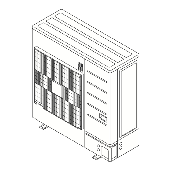
- Page 1 INSTALLATION MANUAL OUTDOOR UNIT For authorized service personnel only. MANUEL D'INSTALLATION UNITÉ EXTÉRIEURE Pour le personnel de service agrée uniquement. MANUAL DE INSTALACIÓN UNIDAD EXTERIOR Únicamente para personal de servicio autorizado. AOU36RLAVS AOU48RLAVS PART No. 9380545187-02...
-
Page 2: Table Of Contents
INSTALLATION MANUAL 1. SAFETY PRECAUTIONS VRF system outdoor unit PART No. 9380545187-02 This installation manual describes how to install the outdoor unit only. To install the indoor unit, refer to the installation manual included with the indoor unit. Contents IMPORTANT! SAFETY PRECAUTIONS …………………………………………………………………... -
Page 3: About This Product
When Connecting Refrigerant Tubing CAUTION This unit must be installed by qualified personnel with a capacity certificate for handling • Keep all tubing runs as short as possible. • Use the brazing method for connecting tubing. refrigerant fluids. Refer to regulation and laws in use on installation place. •... -
Page 4: Special Tools For R410A
For External output (Base heater / CN115) 2.5. About unit of the length All Fujitsu General products are manufactured to metric units and tolerances. United 10-15/16 (278) States customary units are provided for reference only. In cases where exact dimensions and tolerances are required, always refer to metric units. -
Page 5: Installation Dimensions
When the upward area is open Unit: in (mm) 3.3. Installation dimensions (1) Obstacles at rear only (2) Obstacles at front only CAUTION Provide sufficient installation space, such as transportation route, maintenance space, ventilation space, refrigerant piping space, and passageways. Pay attention to the specifications of the installation space as shown in the figure. -
Page 6: System Configuration
Table. A (Wall thickness and pipe material for each diameter) 6-9/16 25-9/16 6-1/16 Unit: in (mm) (166) (650) (154) Outside Diameter 1-15/16 1-15/16 Bolt (mm) (6.35) (9.52) (12.70) (15.88) (50) (50) 0.032 0.032 0.032 0.039 Wall Thickness *2 (mm) (0.8) (0.8) (0.8) (1.0) -
Page 7: Indoor Unit Pipe Connections
5.2. Indoor unit pipe connections Fig. A CAUTION For details, refer to the Installation Instruction Sheet of each part. Service panel Separation tube Horizontal Vertical Outdoor unit or Refrigerant branch kit Fig. B Fig. C Horizontal line Indoor unit or Refrigerant ±... -
Page 8: Electrical Wiring
5.4.2. Bending pipes 6. ELECTRICAL WIRING CAUTION 6.1. The precautions of electrical wiring To prevent breaking of the pipe, avoid sharp bends. Bend the pipe with a radius of curvature of 4 in (100 mm) or more. WARNING If the pipe is bent repeatedly at the same place, it will break. Wiring connections must be performed by a qualified person in accordance with •... -
Page 9: Knockout Hole
6.2. Knockout hole 6.4. Transmission line CAUTION CAUTION Be careful not to deform or scratch the panel while opening the knockout holes. Caution when wiring cable: When stripping off the coating of lead wire, always use the exclusive tool such as a After opening the knockout hole, remove the burr on the edges to prevent snapping of wire stripper. -
Page 10: Wiring Method
6.4.3. Enabling/Disabling automatic address setting 6.5.2. Wiring procedure You can enable/disable automatic address setting for the indoor unit and the signal ampli- • Remove the service panel. And connect the cable to the terminal in accordance with the fier. terminal name plate. To enable automatic address setting for the indoor unit, connect the indoor unit to outdoor •... -
Page 11: External Input And External Output
Shielding the transmission cable 6.6.2. External input terminal Connect both ends of the shielded Wind with insulation tape to prevent short circuit Setting to low noise mode, cooling priority/heating priority selection, outdoor unit operation wire of the transmission cable to peak control setting, emergency/batch stop and electricity meter pulse are possible from the earth (ground) terminal of the the outside. -
Page 12: Field Setting
6.6.3. External output terminal 7.2.2. Terminal resistor setting You can detect the operation condition of outdoor unit and the abnormal situation of both CAUTION indoor and outdoor unit. Be sure to set the terminal resistor according to specifications. Wiring method and specifications Output Connector Status... - Page 13 Normal mode -4.0°F (-20°C) Heating capacity Save energy mode -0.4°F (-18°C) shift *1 High power mode 1 3.2°F (-16°C) High power mode 2 Outdoor tempera- 6.8°F (-14°C) Set this item when necessary. ture zone bound- 10.4°F (-12°C) (Forbidden) ary temperature 14.0°F (-10°C)
-
Page 14: Address Setting For Signal Amplifiers
(1) Turn on the power of the outdoor unit and enter standby mode. 7.5. Address setting for signal amplifi ers • When system is abnormal • When system is normal Check the settings as there is an error in the POWER/MODE lamp lights up. -
Page 15: Resistance Measurement Of Transmission Cable (Measure With Breaker Off)
NOTES: 8. PIPE INSTALLATION II • The automatic address function can be used for a maximum of 8 indoor units installed to the same refrigerant system. When network is connected to other refrigerant systems, Fig. A Connection system Fig. B the automatic address function cannot be used. -
Page 16: Additional Charging
Evacuation procedure (1) Calculation of additional amount for pipe length (1) Remove the caps of the gas pipe and liquid pipe and check that the valves are Total length of ø 3/8 in Total length of ø 1/4 in a × 0.014 a ×... -
Page 17: Test Run
9.1.3. Error displays 9. TEST RUN • When error occurs, “Err” and “Number of errors occurred” are alternately displayed on the 7 segment display every 1 second. 9.1. Indoor unit connection check • For the content of error, please refer to the “10.2. Error codes”. •... -
Page 18: Checklist
Test operation setting method 10. LED STATUS Use the “MODE/EXIT”, “SELECT”, and “ENTER” buttons on the indoor unit PC board to You can determine the operating status by the lighting up and blinking of the LED display. configure settings according to the procedures below. Check the status using the table below.


