Table of Contents
- 1 Table of Contents
- 2 Safety Information
- 3 General Function and Description
- 4 2.0 Accessories
- 5 Specifications
- 6 Fieldmeter Operation
- 7 Voltmeter Operation
- 8 Static Decay Time & Balance Operation
- 9 Remote Field Sensor Probe Operation
- 10 Data Recording & Analog Outputs
- 11 Verification Procedure
- 12 Maintenance/Calibration/Repair of 3M Charge Analyzer 711 & Remote Field Sensor Probe
Table of Contents

Related Manuals for 3M Charge Analyzer 711


Summary of Contents for 3M Charge Analyzer 711
- Page 1 Charge Analyzer 711 Operating Instructions Distributed by: All-Spec Industries 5228 US Hwy 421 N Wilmington, NC 28401 [email protected] www.all-spec.com PH: 800-537-0351 August 2005 FX: 800-379-9903 78-8136-3182-3...
-
Page 2: Table Of Contents
6. Static Decay Time & Balance Operation ....................... 13 7. Remote Field Sensor Probe Operation......................18 8. Data Recording & Analog Outputs ........................ 20 9. Verification Procedure............................ 21 10. Maintenance/Calibration/Repair of 3M Charge Analyzer 711 & Remote Field Sensor Probe ....23 ™ 78-8136-3182-3... -
Page 3: Safety Information
3M™ Charge Analyzer 711. Retain these instructions for future reference. Intended Use: The 3M Charge Analyzer 711 is intended for use in testing the performance of static control products. This device is designed for use as specified in the operating instructions. It is intended for use in an indoor environment and has not been evaluated for other uses or locations. - Page 4 • Avoid extreme discharge of the rechargeable batteries. If the batteries require charging, do not allow the unit to sit idle for a period of time without first fully charging the batteries. • Do not use the charge analyzer 711 or Remote Field Sensor Probe in areas where high AC or DC field strengths are present.
-
Page 5: General Function And Description
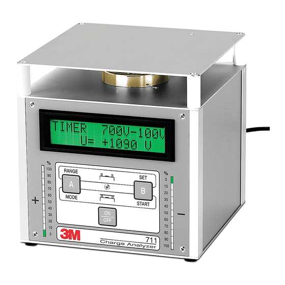
The 3M Charge Analyzer 711 is an electronic test instrument designed for ease of use. The lightweight and ™ compact construction offers great versatility in the workplace. It can be used as a laboratory analytical tool, evaluating the performance of ionizing equipment, static-protective packaging, worksurfaces, and personnel grounding systems. -
Page 6: 2.0 Accessories
2.0 Accessories The 3M Charge Analyzer 711 is shipped in a durable black case with foam interior containing the following ™ accessories: A. Cup electrode I. Insulated bulldog clip B. Plate electrode J. Metal-spacers (3) with thread, 76 mm (3 in.) length C. -
Page 7: Specifications
Specifications Dimensions: Displays: Base unit: (152 x 152 x 152) mm Two, 11-segment positive & negative LED-bar charge (6 x 6 x 6) inches indicators 16-digit alphanumeric dual row LCD Weight: 1,6 kg (3.53 lbs.) Settings: CPM - operating function: Starting voltage: 600 V - 1200 V in 1 V-steps High voltage cascade: Stop voltage: 1 V - 500 V in 1 V-steps... -
Page 8: Fieldmeter Operation
The following procedure zeros each voltage range in the Fieldmeter measurement mode. 1. Ground the charge analyzer 711 by attaching the ground wire with alligator clip on the rear panel of the unit to an earth/electrical ground. - Page 9 Demonstration #1 Testing of Low Tribocharging Tapes With the charge analyzer 711 in the FIELDMETER operating mode, pull the tape off the roll and hold it above the sensor. The digital display reads the field strength in kV/m. To convert readings of kV/m into volts use the following formulas: R/100 x D (cm) or R/39.37 x D (in.) where:...
-
Page 10: Voltmeter Operation
Manual/Auto; 25V, 100V, 500V, 1000V, & 5000V Meter display symbols in Voltmeter mode V = 3M Charge Analyzer 711 in Voltmeter mode (upper left corner). ™ R = Voltage measurement range selected. If range selected is too low OVERFLOW will appear. - Page 11 3. Select the desired voltage range by momentarily depressing the “A” button. Note: If OVERFLOW occurs during the measurement select a higher range. The charge analyzer 711 is now ready to monitor the effectiveness of static control products, measuring electrical charge on people and conductive objects, indicating in volts. 78-8136-3182-3...
- Page 12 Demonstration #2 Performance of a Wrist Strap 1. Hold the cylinder electrode in one hand and perform normal body movements (e.g., sitting down, standing up, walking back and forth, etc.), experienced in the work environment. Observe voltage variations on the 3M ™...
-
Page 13: Static Decay Time & Balance Operation
2. Hold the container by insulating handle being careful not to contact the sides of the container. 3. Charge yourself up by rubbing your feet on a non-static flooring material and touch the container with other hand to charge it. Notice the level of charge on the 3M ™... - Page 14 Voltage range zero procedure: Perform zeroing on first power up. 1. Ground the 3M Charge Analyzer 711 by attaching the ground wire with alligator clip on the rear panel of ™ the unit to an earth/electrical ground. 2. Remove the plate electrode (b) from the Charge Analyzer.
- Page 15 If the “B” button (NO) is depressed you will return to the start of the DECAY TIME menu. The charge analyzer 711 is now ready to measure static charge neutralization effectiveness and the offset balance of ionizers.
- Page 16 Static decay time is defined as the time interval needed to reduce a defined voltage potential on an object to a defined lower potential by means of applied ionized air. Another important aspect for ionizers is the ability to produce a balanced stream of positive and negative ions. The 3M Charge Analyzer 711 can be used to ™...
- Page 17 1. Attach the three metal-spacers (j) by screwing into the three locations at the rear of the Charge Analyzer 711. ™ 2. Position the charge analyzer 711 in front of the ionizer blower with the display facing upward. 3. Measure the static decay rate and offset balance by following the procedure outlined in Demonstration #6 above.
-
Page 18: Remote Field Sensor Probe Operation
Meter display symbols in 3M Remote Field Sensor Mode ™ “EFM” = 3M Charge Analyzer 711 in External Field mode (upper left corner). ™ “D” = Distance between probe and surface to be measured. “U” = Voltage level on charged surface or object. - Page 19 R/100 x D (cm) or R/39.4 x D (in.) where: R = Reading indicated on the analyzer display. D = Distance between object and sensor electrode, measured in inches or centimeters. The charge analyzer 711 is now ready to perform measurements through the remote field sensor probe. 78-8136-3182-3...
-
Page 20: Data Recording & Analog Outputs
Charge Analyzer 711 and observe the voltage. ™ Data Recording & Analog Outputs The charge analyzer 711 has two outputs (analog for a y(t) recorder & digital for a serial PC-COM interface) located at the rear of the unit. Recorder requirements: Internal resistance (R ) greater than 1000 ohms. -
Page 21: Verification Procedure
Verification Procedure The following procedure can be used to determine if the 3M Charge Analyzer 711 is operating within the stated ™ specifications: Equipment required • DC ± 5,000V (≤ ± 1% tolerance) adjustable high voltage power supply • Four lead wires (banana plug style) •... - Page 22 Charge Analyzer 711 ™ Verification Check List Serial Number____________________________________________________________ Date_____________________Inspector___________________________________ P.S. Voltage Range Analog Output & Setting √ √ √ √ Display Voltage (+) Pass (-) (+) Fail (-) (+) Pass (-) (+) Fail (-) ±25Vdc Full Range 25 VDC Full Range 2.0Vdc ±10%...
-
Page 23: Maintenance/Calibration/Repair Of 3M Charge Analyzer 711 & Remote Field Sensor Probe
To reduce the risks associated with property damage due to improper repair or modification: • Do not attempt to modify or repair — no user serviceable parts inside — contact 3M Service for repair To reduce the risks associated with property damage from improper maintenance: •... - Page 24 Warranty; Limited Remedy; Limited Liability. This product will be free from defects in material and manufacture for a period of one (1) year from the time of purchase. 3M MAKES NO OTHER WARRANTIES INCLUDING, BUT NOT LIMITED TO, ANY IMPLIED WARRANTY OF MERCHANTABILITY OR FITNESS FOR A PARTICULAR PURPOSE.