Table of Contents
Quick Links
INSTALLATION MANUAL
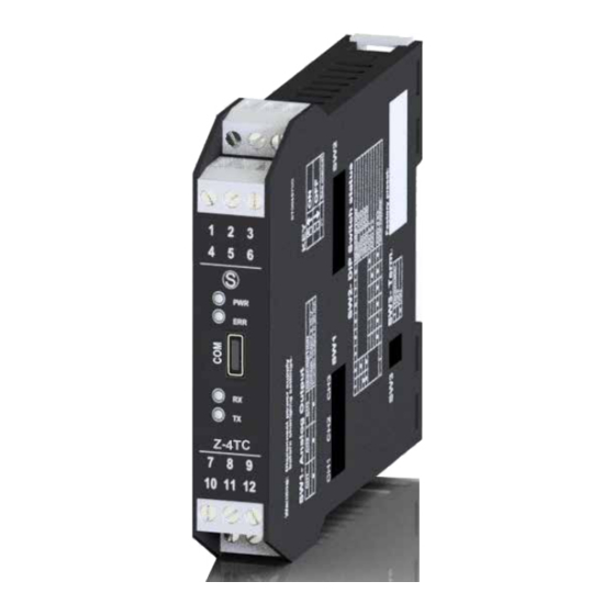
Z-4TC
4 THERMOCOUPLE INPUT module
with Modbus protocol on RS485
E
SENECA s.r.l.
Via Austria, 26 – 35127 – PADOVA – ITALY
Tel. +39.049.8705355 - 8705359 - Fax +39.049.8706287
For manuals in other languages and the configuration software, visit ww.seneca.it/products/z-4tc
MI003631-E
1/8
Table of Contents

Related Manuals for Seneca Z-4TC


Summary of Contents for Seneca Z-4TC
- Page 1 Z-4TC 4 THERMOCOUPLE INPUT module with Modbus protocol on RS485 SENECA s.r.l. Via Austria, 26 – 35127 – PADOVA – ITALY Tel. +39.049.8705355 - 8705359 - Fax +39.049.8706287 For manuals in other languages and the configuration software, visit ww.seneca.it/products/z-4tc MI003631-E...
-
Page 2: Module Layout
WARNING: The full content of this manual must be read before any operation. The module must only be used by qualified electricians. Specific documentation is available at www.seneca.it/products/z-4tc The module must be repaired and damaged parts replaced by the Manufacturer. The product is sensitive to electro- static discharges. -
Page 3: Technical Specifications
TECHNICAL SPECIFICATIONS EN61000-6-4 Electromagnetic emissions, industrial environment. EN61000-6-2 Electromagnetic immunity, industrial environment. STANDARDS EN61010-1 Safety WARNING the maximum working voltage between any Analog mA / V Input mA / V terminal and ground must be less than 50 RS485 mA / V Comm. -
Page 4: Installation Regulations
CONFIGURATION OF FACTORY SETTINGS All DIP-switches in OFF position Communication parameters of ModBUS protocol: 38400 8, N, 1 Address 1 Communication parameters of micro USB front port: 2400 8, N, 1 Address 1 Input type of the 4 inputs: Voltage in mV Scale range of the 4 inputs: ±... - Page 5 USB port, the bus will be inactive; it will reactivate automatically a few seconds after the last message exchanged on the USB port. EASY SETUP is the software to use for the configuration. For more information, visit www.sene- ca.it/products/z-4tc Android APP...
-
Page 6: Setting The Dip Switches
SETTING THE DIP-SWITCHES The position of the DIP-switches defines the Modbus communication parameters of the module: Address and Baud Rate The following table shows the Baud Rate and Address values according to the DIP-switch setting: DIP-Switch status SW1 POSITION SW1 POSITION POSITION BAUD ADDRESS... -
Page 7: Electrical Connections
ELECTRICAL CONNECTIONS Power supply and Modbus interface are available using the Seneca DIN rail bus, via the IDC10 rear connector, or the Z-PC-DINAL-17.5 accessory. Back connector (IDC 10) Power Suppl y AC / + RS485 GND The illustration shows the meanings of the various... -
Page 8: Advanced Settings
Product information [email protected] This document is property of SENECA srl. Copies and reproduction are prohibited unless authorised. The content of this document corresponds to the described products and technologies. Stated data may be modified or supplemented for technical and/or sales purposes.