Table of Contents
Quick Links
See also:
Manual
Table of Contents

Related Manuals for HP 9000 700 Series


Summary of Contents for HP 9000 700 Series
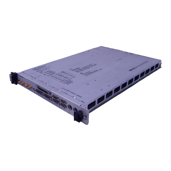
- Page 1 Models V743/64 and V743/100 Owner's Guide HP 9000 Series 700 VXIbus Controllers ABCDE HP Part No. E1497-90016 Printed in USA November 1995 Edition 3 E1195...
- Page 2 Legal Notices The information contained in this document is subject to change without notice. Hewlett-Packard makes no warranty of any kind with regard to this manual, including, but not limited to, the implied warranties of merchantability and tness for a particular purpose. Hewlett-Packard shall not be liable for errors contained herein or direct, indirect, special, incidental or consequential damages in connection with the furnishing, performance, or use of this material.
- Page 3 OSF/Motif is a trademark of the Open Software Foundation, Inc., in the U.S. and other countries. Certication for conformance with OSF/Motif user environment pending. This software and documentation is based in part on the Fourth Berkeley Software Distribution under license from the Regents of the University of California.
- Page 4 Printing History This manual's printing date and part number show its current edition. The printing date will change when a new edition is printed. Minor changes may be made at reprint without changing the printing date. The manual part number will change when extensive changes occur.
- Page 5 Safety Symbols and Conventions The following conventions are used throughout this manual: Notes contain important information set o from the text. Note Caution messages indicate procedures which, if not observed, Caution could result in loss of data or damage to equipment. Do not proceed beyond a CAUTION sign until the indicated conditions are fully understood and met.
- Page 6 Regulatory Information FCC Statement (For U.S.A. Only) The Federal Communications Commission (in Subpart J of Part 15, Docket 20780) has specied that the following notice be brought to the attention of the users of this product: This equipment has been tested and found to comply with the limits for a Class A digital device, pursuant to Part 15 of the FCC Rules.
- Page 7 VCCI Statement (Japan Only)
- Page 8 x x x x x x x x x x x x Replace this page with the Ventura Decl of Conformity x x x x x x x x viii...
- Page 9 Printing Conventions This book uses the following typographical conventions: If you see . . . It means . . . Represents text you will see on the screen or text you must computer text type/enter yourself. For example, login: indicates a login prompt displayed by the system. italic text Variable text supplied by you.
-
Page 11: Table Of Contents
Chapter Contents ..... The HP 9000 Model V743 Embedded VXI Controller ..Features ...... - Page 12 ......Description of HP SICL ....
- Page 13 Conguring for a Backup DDS Tape Drive ..Conguring the Drive on HP-UX ... . . Testing Your Installation ....
- Page 14 B. Using the Boot Console Handler Appendix Contents ....The Boot Console Handler ....Special Tasks .
-
Page 15: Product Description
Product Description Chapter Contents Features. Memory Congurations. Interfaces. Graphics. Operating System. Product Description... -
Page 16: The Hp 9000 Model V743 Embedded Vxi Controller
The HP 9000 Model V743 Embedded VXI Controller The HP 9000 Model V743 VXI controller is an exceptionally exible and responsive high-performance Precision Architecture VXI controller based on the Hewlett-Packard PA-RISC 7100LC technology. Some of the features are Installation Guide for detailed hardware outlined in this chapter. -
Page 17: Memory Con Gurations
The standard Model V743 VXI controller comes with either 16 MB or 32 MB factory-installed RAM, with other options possible. It can be upgraded by the user with internal RAM cards as follows (two cards per upgrade): HP A2578A; 16 MB total. HP A2829A; 32 MB total. HP A2827A; 64 MB total. -
Page 18: Interfaces
The high-density I/O connectors for this board computer require adaptation to standard cabling, using one or more of the following items (these are provided with your controller): HP A4301A RS-232C: High-density 9-pin to standard 9-pin \M". (2) HP A4303A LAN: High-density 15-pin to 15-pin AUI. -
Page 19: Graphics
The Model V743 VXI controller comes with on-board graphics. For information on currently supported monitors, see Chapter 5 in this manual, or the current Release Notes le in /etc/newconfig/905RelNotes HP-UX 9. For Release Notes on HP-UX 10, see the directory. /usr/share/doc Product Description... -
Page 20: Operating System
Operating System Table 1-1 lists the HP-UX operating system features and languages for the Model V743 VXI controller. Table 1-1. Operating System and Languages for the Model V743 VXI Controller Operating system: HP-UX 9.05 or later Languages: HP-PA Assembler 1.1... -
Page 21: Finding Information About Your System
Finding Information About Your System Chapter Contents Manuals for System Information: HP-UX HP VUE Online Sources of Information. Finding Information About Your System... -
Page 22: Overview
Using HP-UX . Appendix in HP VUE is the default interface for HP-UX. At some point, you may want to interact with the Model V743 VXI controller using HP VUE via the LAN, with an X Window System display. As a simpler window alternative, you can also use the X Window System by itself. - Page 23 User's Guide for HP-UX . HP VUE For information on using and conguring the HP VUE interface with HP-UX, HP VUE User's Guide . For information on installing HP VUE, see the see the HP VUE Installation Guide . Finding Information About Your System...
-
Page 24: Online Sources Of Information
HP-UX 9, or the /etc/newconfig /usr/share/doc directory for HP-UX 10. Look for the le named by its release number, for example, , for HP-UX 9.05. 905RelNotes HP-UX and HP VUE Help: For graphics displays, extensive help information on the operating system and the visual interface is included with HP VUE. - Page 25 HP-UX 9, or /etc/newconfig usr/share/doc for HP-UX 10, contains information and new versions of HP-UX product conguration les, as well as shell scripts which may have been customized on your system. The contents of this directory will vary depending on which products you have loaded on your system.
-
Page 27: Getting Started With Hp-Ux
Getting Started with HP-UX Chapter Contents Before Logging In the First Time. Turning On the System. Conguring the Controller. Conguring the RS-232 Ports. Logging In and Out. Creating a New User Account. Setting or Changing a Password. Selecting a New Password. -
Page 28: Before Logging In The First Time
HP-UX clusters and cnodes. This chapter reviews some initial procedures and provides information on using both HP VUE sessions and HP-UX. For more detailed information about using HP VUE User's Guide . HP VUE after login, see the... -
Page 29: System Requirements
Host System: HP Model E1401A or equivalent VXIbus mainframe. HP-UX, installed on a disk accessible to the Model V743 VXI controller. A direct connection to AC power for the mainframe. Avoid using extension power cables or power strips. - Page 30 (for backup of local disk, if installed). Disk congured to the SCSI bus on the Model V743 VXI controller (optional). Some of the more common VXIbus congurations with the Model V743 VXI controller are shown in Figure 3-2. Getting Started with HP-UX...
- Page 31 Figure 3-2. Configurations for the Model V743 VXI Controller Getting Started with HP-UX...
-
Page 32: Turning On The System
\Displaying Graphics on a Remote X Host" in Chapter 5 for the specics of setting this up. 4. Check SCSI connections. 5. Turn on the power to any peripheral devices, but do not turn on the power to the VXIbus mainframe until you have read the following note. Getting Started with HP-UX... - Page 33 To reboot the computer, push the Rst/Abt switch to the \ " (up) position. To exit all currently running processes, push the Rst/Abt switch to the " (down) position. This position is also used when cycling power to reset the monitor conguration and console path. Getting Started with HP-UX...
- Page 34 The following procedure gives you general guidance for setting up the controller as a cnode: 1. Ensure that HP-UX has been installed on the server and that it is appropriately congured as a root server (a cluster that has any Series 700 clients must have a Series 700 root server).
-
Page 35: Con Guring The Controller
") on the panel will blink slowly Boot until HP-UX is booted, then it is continuously on. The other green LED ") will blink when there is VXI backplane access activity. The two red LEDs (second and fourth) will only light if there is a system problem in this VXI system. - Page 36 LAN-congured system for which this system is a valid cluster client. If there are multiple cluster servers that could recognize this client, or if you are installing HP-UX from CD-ROM, you should interrupt the automatic boot selection by pressing the...
-
Page 37: Logging In And Out
This is especially important if your system is attached to a network. Logging In If you are not using HP VUE, then a command line login prompt appears after boot: login: 1. Type your login name (or ). -
Page 38: Logging Out
") appears and you can use the 4 Enter 5 system. Logging Out If you are not using HP VUE, you can use the command to temporarily lock leave your system (while leaving processes running). If you want to log out of... -
Page 39: Creating A New User Account
Using HP-UX and System Administration Tasks give you more details on using SAM. Getting Started with HP-UX 3-13... - Page 40 5. Fill in your login name, choice of start-up program and environment (if dierent from the defaults given), and the optional information. At this point you can select X Windows as your login default Note environment, if you so desire. 3-14 Getting Started with HP-UX...
- Page 41 ). Re-enter the password as requested and choose NNNNNNNN . The re-entered 4 Enter 5 password must match the rst. 8. Choose NNNNNNNN 9. When the \Task Completed" message appears, choose NNNNNNNN 10. Select NNNNNNNNNNNNNN then NNNNNNNNNNNNNNNNNNNNNNNNNN Exit Exit SAM Getting Started with HP-UX 3-15...
-
Page 42: Setting Or Changing A Password
If you are adding many users to your system, see for the details of controlling access to your system. If you have not yet set your password, you can do so using SAM or a shell command line. 3-16 Getting Started with HP-UX... -
Page 43: Powering Down The System
You can do this either from the command line, with SAM, or by using the HP VUE Toolbox. The following procedure uses the conventional HP-UX command. Using the Shutdown Command to Stop Your System 1. -
Page 44: Using The Command Line
Using the Command Line For guidance on entering HP-UX commands and using the HP-UX le system, Using HP-UX . For more tools, and networking commands, see the manual Shells: User's Guide . advanced work with shell programming, see the manual... -
Page 45: ConGuring For A Vxi/Mxi System
Configuring for a VXI/MXI System Chapter Contents Overview. Examining Your VXI/MXI Conguration. Changing Your VXI/MXI Conguration. Conguring the VXI/MXI Trigger Lines. Examining the VXI/MXI Boot Process. Using HP SICL for VXIbus Backplane Communication. Configuring for a VXI/MXI System... - Page 46 Overview If your Model V743 VXI controller is to be a node in an HP-UX cluster, and it has not yet been installed and congured according to the procedures in the Installation Guide for the Model V743 VXI controller, see \Conguring the Controller"...
-
Page 47: Default Values
Examining Your VXI/MXI Configuration Default Values Your Model V743 VXI controller comes precongured from the factory as follows: VXI Logical Address : 0. VXI Servant Area Size : 255. VXI Bus Error Timeout : 1ms. VXI Shared Memory : 0 (disabled). The above values are programmed into the Model V743 VXI controller EEPROMs at the factory. -
Page 48: Changing Your Vxi/Mxi Con Guration
VXI shared memory in A24 address space. The Model V743 VXI controller is shipped with this feature disabled. When enabled, 1 MByte of the system memory becomes unavailable for use by HP-UX and your applications. Instead, this memory is mapped onto the VXI backplane for use as VXI shared memory. - Page 49 Configuring the VXI/MXI Trigger Lines Figure 4-1. Front Panel Trigger I/O The table listed on the next page shows the relationship between SICL and the Model V743 VXI controller trigger lines and SMB connectors. Configuring for a VXI/MXI System...
- Page 50 Trigger Lines SICL V743 I TRIG TTL0 TTL0 I TRIG TTL1 TTL1 I TRIG TTL2 TTL2 I TRIG TTL3 TTL3 I TRIG TTL4 TTL4 I TRIG TTL5 TTL5 I TRIG TTL6 TTL6 I TRIG TTL7 TTL7 I TRIG ECL0 ECL0 I TRIG ECL1 ECL1 I TRIG ECL2...
-
Page 51: Routing Vxi Ttl Trigger Lines In A Vxi/Mxi System
TTL7 to Trig out, you can use the following SICL function call in your program: ivxitrigroute (id, I_TRIG_TTL7, I_TRIG_EXT1); HP SICL Reference Manual for more information on this and other See the SICL functions. Routing VXI TTL Trigger Lines in a Multiple Mainframe System When you have multiple mainframes connected via the MXIbus, the TTL trigger lines are not routed from one mainframe to another. - Page 52 VXI-MXI TTL Trigger Routing: Name 0 1 2 3 4 5 6 7 ---- - - - - - - - - hpvximxi I I I I I I I I I - MXI->VXI O - VXI->MXI * - Not Routed Now the following illustrates TTL trigger line 1 being sourced by the device at logical address 24: le:...
- Page 53 MXI/INTX trigger and interrupt circuitry. See Appendix HP SICL F, \Conguring your VXI/MXI System," in the User's Guide for HP-UX for information on this and other diagnostic tests for the E1489 MXIbus Controller Interface. Inverting the Polarity of the Model V743 VXI Controller External...
-
Page 54: Examining The Vxi/Mxi Boot Process
Examining the VXI/MXI Boot Process When HP SICL is installed and congured according to the procedures in the HP SICL User's Guide for HP-UX , certain SICL utilities are copied onto your system. These utilities automatically run when the system boots. The... -
Page 55: Viewing The Vxibus System Con Guration
These les are not HP SICL User's usually edited except under special circumstances. See the Guide for HP-UX for more details on these les and when you want to make changes to them. Configuring for a VXI/MXI System... - Page 56 VXI/MXI Configuration Files Conguration Description File Contains a database that cross references the VXI manufacturer id vximanuf.cf numbers and the name of the manufacturer. Edit this le if you add a new VXI vendor that is not currently in the le. Contains a database that lists a cross reference of manufacturer id, vximodel.cf model id, and VXI device names.
-
Page 57: The Iproc Utility (Initialization And Sysreset)
Note un-comment the following line in the /usr/pil/etc/iproc.cf le on HP-UX 9, or the le on /etc/opt/sicl/iproc.cf HP-UX 10, in order for the resource manager to run on SYSRESET. sysreset vxi ivxirm -t 5& Configuring for a VXI/MXI System 4-13... -
Page 58
The following is an example of the le: /usr/pil/etc/iproc.cf # iproc configuration file # Boot up functions # Lines are of the form: boot
boot echo "PIL: Instrument I/O Initialization" # The next line must always exist. boot pilsetup # V/382 or VXI/MXI Support boot ivxirm -p -I vxi # When a SYSRESET occurs, rerun the resource manager (delay 5 sec). - Page 59 Using HP SICL for VXIbus Backplane Communication Once your VXIbus system is congured, you can start programming with SICL. SICL allows you to communicate directly over the VXIbus backplane to SCPI compatible message-based and register-based instruments. With the SICL C library, you simply open a communications session with the...
-
Page 60: For More Information
/* print contents of buf */ printf ("%s\n", buf); /* close device session */ iclose (id); For More Information HP SICL User's Guide for HP-UX and the HP SICL Reference Manual See the for information on using HP SICL. 4-16 Configuring for a VXI/MXI System... -
Page 61: ConGuring Graphics
Configuring Graphics Chapter Contents Monitor Selection. Displaying Graphics on a Remote X Host. Configuring Graphics... -
Page 62: Overview
HP-UX 9, or /etc/newconfig usr/share/doc HP-UX 10) or the Support Matrix available from your HP support engineer. Configuring for a New Monitor Note that conguration of the Model V743 VXI controller to recognize new monitors is accomplished interactively by the boot console handler by following the procedure in \Conguring the Console Path and Display Format"... -
Page 63: Identifying Graphics Cards
For More Information For detailed information on running HP VUE in a networked environment, see HP VUE User's Guide . For additional information on conguration for graphics formats, see \Conguring the Console Path and Display Format" in Appendix B in this manual. -
Page 65: ConGuring Hp-Ux For Printers
Configuring HP-UX for Printers Chapter Contents Preparing for Installation. Testing the Printer Installation. Dealing With Printer Problems. Configuring HP-UX for Printers... -
Page 66: Preparing For Installation
If you don't want to use SAM to install the printer, or if SAM is not on your system, you can also use HP-UX commands directly to accomplish the same tasks. For information on using manual system administration procedures for System Administration Tasks . -
Page 67: Con Guring Hp-Ux For A Printer
Printer Model Number (located on a label on the back of the printer): Printer Cables For serial data exchange, you will need the following: HP A4301A (Serial): 9-pin high density to standard 9-pin \M". (Two of these cables are provided with the Model V743 VXI controller.) Other standard cables may be required. - Page 68 6. Choose an appropriate selection on the sub-menu giving options for Serial, HP-IB, etc. 7. A screen will give you information on available serial or parallel interfaces. 8. On HP-UX 9, if you choose NNNNNNNNNNNNNNNNNNNNNNNNNNNNNNNNNNNNNNNNNNNNNNNNNNNNNNNNNNNNNNNNNNNNNNNNNNNNNNNNNNNNNNNNNNNNNNNNNNNNNNNNNNNNN Add Serial (RS-232C) Printer/Plotter more than one serial interface could be listed. The serial interfaces are listed in ascending order.
-
Page 69: Testing The Printer Installation
) isn't the default system printer, enter the (If your printer (called following command to test it:) printername lp -d .profile 4 Enter 5 The le named should print out on the new printer. .profile Configuring HP-UX for Printers... -
Page 70: Dealing With Printer Problems
Paper is loaded into the printer (and it isn't jammed). The correct interface has been set up. The printer cable is connected to the correct interface port on your printer. The cable is connected to the correct port on your system. Configuring HP-UX for Printers... -
Page 71: ConGuring Hp-Ux For A Dds Tape Drive
Configuring HP-UX for a DDS Tape Drive Chapter Contents Finding the Status of Existing SCSI Bus Addresses. Conguring for a Backup DDS Tape Drive. Conguring the Drive on HP-UX. Testing Your Installation. DDS Tape Drive LED Indicators. Maximum Usage of DDS Cassettes. - Page 72 HP35450A disk 2.0.1.6.0 scsi ok(0x101) MICROP 1528 For example, the SCSI bus address for the HP 35450A tape device is in the fourth column of its hardware address as \ " ( ). The following 2.0.1. procedure outlines how to use SAM for installing a tape drive.
- Page 73 You will need to use a backup device if you have local disks connected to the Model V743 VXI controller. This section contains instructions for conguring an external DDS drive on HP-UX to use for backup. Tape Selection The DDS (\Digital Data Storage") tape drive is a sequential-access, read-write device using removable DDS cassettes.
- Page 74 The general steps for adding a DDS tape drive to your system are as follows: 1. Make sure that the necessary device drivers are congured into the kernel. On HP-UX, SAM will make this test. 2. Shut your system down and turn o the power.
- Page 75 (eventually) reboot the system. Select from the menu on NNNNNNNNNNNNNNNNNNNNNNNNNNNNNNNNNNNNNNNNNNNNNNNNNNNNNNNNNNN screen whether you want to create the new Create a New Kernel kernel now, later, or cancel the proposed modications. (Make sure your Configuring HP-UX for a DDS Tape Drive...
- Page 76 /SYSBCKUP server's kernel. Your system is now running the added driver for SCSI DDS tape drive. You are ready to use the drive to load a tape into your system. Configuring HP-UX for a DDS Tape Drive...
-
Page 77: Testing Your Installation
Note that the command may fail with a busy error if the command is executed before the tape has completed loading. Configuring HP-UX for a DDS Tape Drive... -
Page 78: Dds Tape Drive Led Indicators
Two LED indicators on the front panel of the drive indicate several operational and test states. The following table shows the LED combinations and explains what they indicate. Table 7-1. DDS Tape Drive LED State Codes Configuring HP-UX for a DDS Tape Drive... - Page 79 Configuring HP-UX for a DDS Tape Drive...
-
Page 80: Maximum Usage Of Dds Cassettes
Sustained use at low humidity. Backup software requiring certain areas of the tape being accessed frequently. As a guideline, HP recommends that the number of backup operations should be limited to 100 per cassette in extreme cases of the above conditions. -
Page 81: Backing Up And Restoring Software
Backing Up and Restoring Software Chapter Contents Backing Up Your HP-UX System and Software. Restoring Individual Files. Restoring HP-UX Using the Recovery Tape. Backing Up and Restoring Software... -
Page 82: Backing Up Your Hp-Ux System And Software
Restore your le system, if needed. Creating a Recovery System A \recovery system" is a special tape containing a subset of the HP-UX operating system. In the event of an operating system failure that prevents you from booting or logging into HP-UX, you can boot from the recovery system tape and use the tools on the tape to repair the le system on your disk. - Page 83 Using to Create a Recovery System on HP-UX 9 utility on HP-UX 9 constructs a recovery system on removable media mkrs (or on a formatted hard disk drive). If a system later becomes unbootable due to a corrupt root disk, then you can boot your system from the recovery tape.
- Page 84 Source Device Files By default, uses the following device les: mkrs /dev/update.src /dev/rct/c0 /dev/rct one of these device les If none of the above defaults exist on the system, must be created or the option must be used to specify the device le. The recovery device le can be either a block or a character device le.
-
Page 85: Backing Up Your File Systems
Backing Up Your File Systems Preparation: The following procedure sets up a scheduled backup: 1. If your system is more than six months old, you have non-HP supported System Administration software, or you have never done a backup before, see Tasks before proceeding. - Page 86 not write-protected by 2. Before initiating the backup, verify that your tape is checking that the write-protect device is in \writable" position. 3. Load a tape into the tape drive. Depending on what tape drive you are using, you may see activity lights ashing while the tape is loading. You can proceed when one light remains on, indicating that the drive is ready to accept data.
-
Page 87: Restoring Individual Files
/usr/etc/exportfs command to export the correct permissions. Refer to exportfs (1M) in the HP-UX Reference and the Installing and Administering NFS Services manual. To restore individual les: 1. Ensure that you have capabilities. - Page 88 3. Choose NNNNNNNNNNNNNNNNNNNNNNNNNNNNNNNNNNNNNNNNNNNNNNNNNNNNNNNNNNN Backup and Recovery 4. Choose NNNNNNNNNNNNNNNNNNNNNNNNNNNNNNNNNNNNNNNNNNNN NNNNNNNNNNNNNNNNNNNNNNNNNNNNNNNNNNNNNNNNNNNNNNNNNN , or Backup Devices Automated Backup NNNNNNNNNNNNNNNNNNNNNNNNNNNNNNNNNNNNNNNNNNNNNNNNNNNNNNNNNNNNNNNNNNNNNNNNNNNNNNNNNNNNNNNNNNNNNNN Interactive Backup and Recovery 5. Highlight the device in the list from which the data is to be restored. 6. Choose NNNNNNNNNNNNNNNNNNNNNNNNNNNNNNNNNNNNNNNNNNNNNNNNNNNNNNNNNNNNNNNNNNNNNNNNNNNNNNNNNNNNNN from the NNNNNNNNNNNNNNNNNNNNNNN menu and Recover Files or Directories...
- Page 89 8. To do any of the following during the restore process, activate NNNNNNNNNNNNNNNNNNNNNNNNNNNNNNNNNNNNNNNNNNNNNNNNNNNNNNNNNNNNNNNNNNNNNNNNNNNNN Set Additional Parameters Overwrite new les. Maintain original ownership. Recover les using full path name. Place les in a non-root directory. Turn on the appropriate checkbox(es). To restore les relative to a particular directory, ll in the directory. NNNNNNNN Choose to set the additional parameters.
-
Page 90: Restoring Hp-Ux Using The Recovery Tape
le system. If your system disk (including on HP-UX 9, or /SYSBCKUP on HP-UX 10) is unbootable, do the following: /stand/system.prev not write-protected. HP-UX needs to have 1. Verify that the recovery tape is write access to your recovery tape when you boot it. - Page 91 77 Reset the System ---------------------------------------------- To boot from a device, Press Key, then press [Enter/Return] 7. Select the DDS drive (product number HP 35450A, in the example) by typing the number of the line for the device (\ ", in the example) followed 4 Enter 5 8.
-
Page 92: For More Information
Using the command to copy the le on HP-UX 9 or the /hp-ux le on HP-UX 10 from your memory-based system /stand/vmunix real (it is a copy of your le) to the directory you used as a /hp-ux mount point for your system disk. -
Page 93: Dealing With Problems
Dealing With Problems Chapter Contents Interpreting LED Indicators. Managing a Boot Failure. Selecting an Alternate Operating System. Recovering from a System Panic. Dealing with Network Failures. Dealing With Problems... -
Page 94: Interpreting The Led Indicators
Interpreting the LED Indicators There are four LEDs, which you can view on the panel of the Model V743 VXI controller, next to the clock and trigger I/O. LED Behavior Blinks occur in blinks/second groups. Each blink pattern is repeated at one-second intervals: Figure 9-1. - Page 95 Table 9-1. Front Panel LED Indications Behavior Meaning Remedy Boot/Run continuously Power failure Check DC power supply on (Green) VXI mainframe. Check AC power. continuously Normal status No action needed. One blink/second CPU failure Replace system board. Four No console Check console path and blinks/second identied...
-
Page 96: Managing A Boot Failure
Managing a Boot Failure The boot program is located in the rmware of the Model V743 VXI controller. You can congure the behavior of the boot process by interacting with the boot console handler. See Appendix B for procedures dealing with the boot console handler. -
Page 97: Selecting An Alternate Operating System
Selecting an Alternate Operating System If your hardware is functioning correctly, but your usual boot device (such as the root disk) is not responding as it should, you can select an alternate available boot device manually by following these steps: 1. - Page 98 In this case, you should recheck the connection to the SCSI devices and try the boot again. If this still results in no devices being listed, contact your HP Service Representative for assistance. If the search locates a disk, enter the device selection number (\ ", in...
-
Page 99: Recovering From A System Panic
Sometimes they occur as the result of a hardware failure. In a clustered HP-UX environment, a diskless client node will panic if too much time has elapsed since its last communication with its server. This could be the result of nothing more than a LAN cable that has been disconnected for too long. - Page 100 , for fsck reboot -n HP-UX, for any subsequent reboots required by . See fsck Solving HP-UX Problems Chapter 6 \File System Problems," in for detailed information. Ensure the integrity of all LAN connections, including taps in any AUI cable.
-
Page 101: Procedures For Recovering From A System Panic
In a log book, record and categorize the panic message displayed on the system console. The panic message will tell you why the operating system panicked. Sometimes panic messages refer to internal structures of HP-UX (or its le systems) and the cause might not be obvious. Generally, the problem is in one... - Page 102 System . In this case, it is especially important that you write down the text of the panic message, just in case you need it for future troubleshooting or help from HP service personnel. Step 3: Rebooting Your System Once you have checked for and corrected any problems from Step 2, you are ready to reboot your system.
- Page 103 le system, will ask you to reboot your system fsck when it's nished. When you do this on an HP-UX system, use the following command: reboot -n option tells not to sync the le system before rebooting. Since...
- Page 104 For Further Information Solving HP-UX Problems and System Administration Tasks for Refer to further information. To restore a corrupted HP-UX operating system, see the procedures for restoring in Chapter 8 of this manual. 9-12 Dealing With Problems...
-
Page 105: Dealing With Network Failures
Dealing with Network Failures If the program you have been running uses resources from a local area network (LAN) and it stops unexpectedly, the following may help locate the source of the problem: Table 9-3. Problems with the Network Problem Action No systems respond to the Check the network connection on the... -
Page 107: Installing Additional Memory
Installing Additional Memory Appendix Contents RAM Upgrade Products. Planning for Installation of RAM. Installing the RAM Boards. Installing Additional Memory... -
Page 108: Ram Upgrade Products
RAM Upgrade Products The RAM upgrades for the Model V743 VXI controller are as follows (two cards per upgrade product): HP A2578A: 16 MB total. HP A2829A: 32 MB total. HP A2827A: 64 MB total. This Appendix is a general guide to RAM installation. For detailed... -
Page 109: Planning For Installation Of Ram
Planning for Installation of RAM Determining Existing Memory Follow these steps to determine how much memory your Model V743 VXI controller already has: on . If the mainframe is already on , cycle 1. Turn the VXIbus mainframe o and back on .) power (turn it 2. -
Page 110: Installing The Ram Boards
Installing the RAM Boards 40,000 volts can be generated on a A static charge of almost Caution carpeted oor. This exceeds the limits of these RAM cards and can cause unsuccessful operation or damage. Integrated circuits on printed circuit boards can be damaged by electrostatic discharge. - Page 111 3. Turn o the power for the VXIbus mainframe. 4. While facing the front panel of the board computer, use a at-tipped screwdriver to remove the two screws at the corners of the panel. Figure A-1. Extracting the Controller 5. Spread the two handles on the front panel. This will have the action of extracting the board computer out of its rear connector.
- Page 112 Figure A-2. Removing RFI Cover 8. Using the Pozidriv screwdriver, remove the screw holding the RFI cover (with specications printed on it) from the top side of the board. 9. Place the tip of a at-tipped screwdriver through the slot in the RFI cover back about 8mm next to to the screw hole.
- Page 113 Note the L-shaped side tabs on the top cover that t through the system board and into the bottom cover on each side. Moving the RFI cover back also disengages these tabs. 10. Raise the back end of the RFI cover and remove the cover. Cards are 11.
- Page 114 13. Snap the RAM card in place by moving it from vertical position to the angle of the old cards (or approximately 25 ). The ends of the card will snap into the spring clips at 25 14. Install the other member of the RAM pair the same way, in the adjacent slot toward the front panel.
- Page 115 not listed, turn o the VXIbus mainframe 19. If the correct total memory is and remove the board computer. a. Verify that the RAM cards are installed in adjacent pairs (front pair or rear pair). b. Verify that no RAM card connectors are dirty. 20.
-
Page 117: Using The Boot Console Handler
Using the Boot Console Handler Appendix Contents The Boot Console Handler. Special Tasks. Boot Console Information Display. Using the Boot Console Handler Interface. Conguring the Console Path and Display Format. Booting and Resetting the VXIbus Mainframe. Searching for Bootable Media. Displaying and Setting Paths. -
Page 118: The Boot Console Handler
This appendix gives you guidance on the functions of the boot console handler which especially relate to using HP-UX. Most of these tasks can be performed by selecting from menus, or by using the default values set in the EEPROM at the factory. -
Page 119: Using The Boot Console Handler Interface
Note i , the I/O ASIC selections may list used with the Model 743 some device options such as HP Parallel not in the Model V743 VXI controller. Using the Boot Console Handler Interface To use the boot console handler menus, follow these steps: 1. - Page 120 Specifying a Boot Device To display devices that can boot HP-UX, type . A list of potential boot 4 Enter 5 devices will be displayed. For example: ==== BOOT FROM DEVICE ======================== Key Boot Device --- ----------------------------------------- 1 SCSI.6.0 HP C2233 2 LAN.080009-72333...
- Page 121 Setting the Console Path If you are using a graphics display or if you are changing from graphics to a RS-232C display mode, you will need to set the Console Path. 1. Press at the prompt \ . . . " System Search started 4 ESC 5 2.
- Page 122 3. Turn on the VXIbus mainframe power. 4. Release the Rst/Abt switch. 5. You will begin seeing a set of messages on your screen, some of which will display clearly and some of which will not. The messages repeat the same content and each will remain on your display for about seven seconds.
- Page 123 You have selected this device as the CONSOLE CAUTION Before selecting 77 or 99: Set the CONSOLE PATH to this device, then Deselect INTERACTIVE CONSOLE SEARCH This graphic device MONITOR TYPE is KEY 3 6. After the monitor or console type is conrmed, your console display shows NNNNNNNNNNNNNNNNNNNNNNNNNNNNN .
- Page 124 To Select a Type, press Key, then press [Enter/Return] The selected set of parameters should describe your monitor. You can check this information in your HP-UX 9.05 Release Notes (see \Online Sources of Information" in Chapter 2). To change console conguration, you can press the appropriate key here,...
-
Page 125: Booting And Resetting The Vxibus Mainframe
Booting and Resetting the VXIbus Mainframe In case you do not want the usual automatic boot sequence to occur, you can start your system from an operating system that is stored on a device that is dierent from your usual boot device. If your normal operating system kernel or the disk on which it resides becomes damaged or unusable, you may wish to boot from a dierent disk or perhaps another type of device, such as a DDS-format tape drive. -
Page 126: Searching For Bootable Media
Searching for Bootable Media Unless congured otherwise in the boot console handler, the boot console process will automatically search exhaustively for bootable media. In automatic mode, the boot process searches all types of I/O devices in the default order for that operating mode (Test, OEM, or User), or in another NNNNNNNNNNNNNNNNNNNNNNNNNNNNNNNNNNNNNNNNNNNNNNNNNN order, if you have so specied in the menu. -
Page 127: Displaying And Setting Paths
Displaying and Setting Paths A path is the hardware address of a device that is attached to the I/O system of your system. To display the current settings for the system paths, select NNNNNNNNNNNNNNNNNNNNNNNNNNNNNNNNNNNNNNNNNNNNNNNNNNNNNNNN from the boot console NNNNNNNNNNNNNNNNNNNNNNNNNNNNN by typing Path Configuration MAIN MENU 4 Enter 5... - Page 128 ==== PRIMARY PATH ============================ PRIMARY PATH is now [ SCSI.6.0 ] Key Device Path --- ----------------------------------------- 1 SCSI.6.0 HP C2233 2 LAN.080009-72333 15.99.255.25 3 SCSI.4.0 CD-ROM HP C2943A ..........0 Previous Menu 66 Update Device Path list 77 Reset the System ----------------------------------------------...
- Page 129 Selecting the Alternate Path Select the Alternate Path in a similar way by going to the NNNNNNNNNNNNNNNNNNNNNNNNNNNNNNNNNNNNNNNNNNNNNNNNNNNNNNNN menu and typing to see the NNNNNNNNNNNNNNNNNNNNNNNNNNNNNNNNNNNNNNNNNNNN PATH CONFIGURATION ALTERNATE PATH 4 Enter 5 menu. Resetting the Boot Device List Resetting the search list for primary or alternate boot devices is a similar process to setting paths in general.
- Page 130 ==== PRIMARY PATH ============================ PRIMARY PATH is now [ SCSI.6.0 ] Key Device Path --- ----------------------------------------- 1 SCSI.6.0 HP C2233 2 LAN.080009-72333 15.99.255.25 3 SCSI.4.0 CD-ROM HP C2943A ..........0 Previous Menu 66 Update Device Path list 77 Reset the System ----------------------------------------------...
-
Page 131: Displaying And Setting The Secure Boot Mode
Displaying and Setting the Secure Boot Mode There may be circumstances in which you would not wish to allow anyone to attempt to boot your system from a device other than the device you have specied, or to control the system from any console other than the one you have designated. - Page 132 Type to get the NNNNNNNNNNNNNNNNNNNNNNNNNNNNNNNNNNNNNNNNN menu, which will look something like CONTROL FLAGS 4 Enter 5 the following: ==== CONTROL FLAGS ========================= Mode is now [ USER ] Key Enable Control Feature --- ----------------------------------------- 1 NO Fast Boot 2 NO Secure Mode 3 YES Auto Boot Select...
- Page 133 Once the secure boot mode is activated, the only way to Caution deactivate it is to use the Rst/Abt switch, as in the previous section \Setting the Console Display Format" in this Appendix. This procedure is outlined below: o and the 1.
-
Page 134: Displaying The Lan Station Address
Displaying the LAN Station Address The LAN station address (\LANIC ID") of your system is the label that uniquely identies the LAN connection for it at the link level (the hardware level). It is sometimes necessary for you to supply this address to other users. For example, if your system is to become a member of a cluster, the cluster administrator needs to know your LAN station address in order to add your system to the cluster. -
Page 135: Interactive Testing
77 Reset the System ---------------------------------------------- Press Key, then press [Enter/Return] Note the third item in the list, which is the LAN address. (The item \HP PARALLEL" does not apply to the Model V743 VXI controller.) Interactive Testing This menu allows you to run selected tests, and it allows access to the debugger environment. - Page 136 The tests are as follows: NNNNNNNNNNNNNNNNNNNNNNNNNN : tests the CPU super scalar operations. CPU S.S. NNNNNNNNNNNNNNNNNNNNNNNNNNNNNNNN : initializes and tests the specied graphics interface. (Only GRAPHICS 1 GRAPHICS 1 is supported on the Model V743 VXI controller.) If the specied graphics interface is the console, the test will not be run but it will report \passed".
-
Page 137: Displaying Firmware Information
Displaying Firmware Information. This menu will give you information on the rmware module revision NNNNNNNNNNNNNNNNNNNNNNNNNNNNN number. To get to this menu, at the , type MAIN MENU 4 Enter 5 NNNNNNNNNNNNNNNNNNNNNNNNNNNNNNNNNNNNNNNNNNNNNNNNNNNNNNNNNNNNNN ). You will see a menu similar to the following: FIRMWARE INFORMATION ==== FIRMWARE INFORMATION ==================== PDC Version 310.0 Release 0 Extension ROMs... -
Page 139: Glossary
(\/") and ending with the le base name itself. If the path name directory , leave the trailing slash. For example, indicates a /users/jth/ Using HP-UX for more information on path names and directory structures in HP-UX. access permissions read, write , and execute ) which... - Page 140 HP-UX. bus address A number which makes up part of the address HP-UX uses to locate a particular device. The bus address is determined by a switch setting on a peripheral device which allows the computer to distinguish between two devices connected to the same interface.
- Page 141 Glossary cluster client A cluster node that does not have a local HP-UX le system. Its le system resides on the cluster server. A client can also refer to any process run by a server. cluster node Any workstation networked into an HP-UX cluster. (Also called \cnode".)
- Page 142 A table of identiers and references (such as le names) that refer to corresponding les and items of data. Used in a typical HP-UX organizational structure to provide an organizational and logical identity for a given group of les and directories.
- Page 143 Initial System Loader. This implements the operating system-independent portion of the boot process. kernel The part of the HP-UX operating system that manages the computer's resources, such as memory, le system, and input/output. Korn Shell An HP-UX shell, featuring command history recall and line-editing.
-
Page 144: Contents
This may be any group of characters, so long as it meets system rules. mainframe A VXIbus cardcage which allows instruments on a card to be plugged in and operate in a VXI environment. The HP E1401 is an example of an HP mainframe. mount To add an auxiliary (removable) le system to an active existing le system. - Page 145 (1) command or the chown (2) system call. with the password An encrypted sequence of characters used by HP-UX to identify an authorized user and to permit authorized login on a system. path name A sequence of directory names, separated by slashes, which specify the location of any le or directory.
- Page 146 The highest level directory of the hierarchical le system, from which all other les branch. In HP-UX, the slash ( ) character refers to the \root directory." The root directory is the only directory in the le system that is its own \parent directory."...
- Page 147 Glossary System Administration Manager. A subsystem of HP-UX that does a wide range of system administration tasks interactively. SCPI Standard Commands for Programmable Instruments. script A le that contains commands that a shell can interpret and run. SCSI Small Computer System Interface.
- Page 148 Internet Protocol (IP) number is sometimes used instead of a system name to identify the system. tree structure The HP-UX method of organizing les and directories into a branching hierarchical structure. This structure looks like an inverted tree with the \root" directory at the top, descending into multiple directory/le branches that end in clusters of les.
- Page 149 The medium through which users communicate with their workstations. The command-line prompt is one type of interface. The graphical objects of HP VUE are another type of interface. Versa Module Eurocard. A backplane connector protocol, used for networking customized arrays of processor boards in the same chassis.
-
Page 151: Index
Index Index using, B-2{21 Special characters boot console handler, B-2{21 , 9-8 reboot\ {-}n boot device , 3-11{13 alternate, 9-5 , 3-11, 3-12 booting the system, 3-6 boot paths setting, B-11 function, 3-7, B-5, B-17 boot problems, 9-4, 9-5 account boot process utilities, 4-10 user, 3-13 boot program, 9-4... - Page 152 Index , 8-7{9 DDS tape frecover , 8-10{11, 9-8, 9-10, 9-11 cautions, 7-10 fsck , 7-7 maximum usage, 7-10 ioscan , 3-12 recovery systems, 8-2 lock , 2-4 default values, 4-3 mkrs , 8-3{4 denitions, terms, Glossary-1{11 , 3-16 determining active bus IDs, 7-2 passwd , 9-10, 9-11 display conguration, 3-5, 3-6...
- Page 153 9-10 , 3-12 lock LED indications logging in, 3-11 DDS drive, 7-8 logging out, 3-12 HP-UX, 9-2{3 HP-UX recovery, 8-10 LED indicators, 3-6 HP VUE, 3-2 front panel LEDs, 7-8, 9-2, 9-3 , 3-12 lock logging in, 3-11 , 4-9...
- Page 154 Release Notes nding, 2-4 resource manager, 4-10 panic restoring, 8-2{6 system, 9-7 restoring HP-UX, 8-10{12 panic message, 9-9 restoring HP-UX le system, 8-10{12 , 3-16 passwd restoring individual les, 8-7{9 password changing, 3-16 boot interface, B-2{21 criteria, 3-16 root account, 3-13...
- Page 155 9-7{12 nding existing, 7-2 TTL trigger lines SCSI bus IDs routing, 4-7 determining active, 7-2 turning on, 3-6 secure boot mode, B-15 HP-UX, 3-11 , 3-10 set_parms setting display, B-5 shared memory unused SCSI bus address enabling/disabling, 4-4 nding, 7-2...