
Related Manuals for YASKAWA VIPA System MICRO M13-CCF0000


Summary of Contents for YASKAWA VIPA System MICRO M13-CCF0000
- Page 1 VIPA System MICRO CPU | M13-CCF0000 | Manual HB400 | CPU | M13-CCF0000 | en | 16-47 SPEED7 CPU M13C www.vipa.com/en/service-support/manual...
- Page 2 VIPA GmbH Ohmstr. 4 91074 Herzogenaurach Telephone: 09132-744-0 Fax: 09132-744-1864 Email: [email protected] Internet: www.vipa.com M13-CCF0000_000_CPU M13C,1,EN - © 2016...
-
Page 3: Table Of Contents
VIPA System MICRO Table of contents Table of contents General........................7 1.1 Copyright © VIPA GmbH ................. 7 1.2 About this manual..................... 8 1.3 Safety information..................... 9 Basics and mounting................... 10 2.1 Safety information for users................10 2.2 System conception..................10 2.3 Dimensions..................... - Page 4 VIPA System MICRO Table of contents 4.7.2 Parameter CPU................... 63 4.8 Setting VIPA specific CPU parameters............66 4.9 Project transfer....................68 4.9.1 Transfer via Ethernet................... 68 4.9.2 Transfer via memory card................68 4.9.3 Option: Transfer via MPI................69 4.10 Accessing the web server................70 4.10.1 Access via the Ethernet PG/OP channel...........
- Page 5 VIPA System MICRO Table of contents 5.6.7 Diagnostics and interrupt................117 5.7 Frequency measurement................117 5.7.1 Properties....................117 5.7.2 Wiring......................118 5.7.3 Proceeding....................120 5.7.4 Parametrization..................120 5.7.5 Status indication..................122 5.8 Pulse width modulation - PWM..............123 5.8.1 Properties....................123 5.8.2 Wiring......................
- Page 6 VIPA System MICRO Table of contents 9.2.2 Catalog ..................... 182 9.3 SPEED7 Studio - Hardware configuration - CPU......... 184 9.4 SPEED7 Studio - Hardware configuration - Ethernet PG/OP channel..184 9.5 SPEED7 Studio - Hardware configuration - I/O modules......187 9.6 Deployment I/O periphery................
-
Page 7: General
VIPA System MICRO General Copyright © VIPA GmbH General 1.1 Copyright © VIPA GmbH All Rights Reserved This document contains proprietary information of VIPA and is not to be disclosed or used except in accordance with applicable agreements. This material is protected by the copyright laws. It may not be reproduced, distributed, or altered in any fashion by any entity (either internal or external to VIPA), except in accord- ance with applicable agreements, contracts or licensing, without the express written con- sent of VIPA and the business management owner of the material. -
Page 8: About This Manual
VIPA System MICRO General About this manual VIPA GmbH, Ohmstraße 4, 91074 Herzogenaurach, Germany Telefax: +49 9132 744-1204 EMail: [email protected] Technical support Contact your local VIPA Customer Service Organization representative if you encounter problems with the product or have questions regarding the product. If you are unable to locate a customer service centre, contact VIPA as follows: VIPA GmbH, Ohmstraße 4, 91074 Herzogenaurach, Germany Tel.: +49 9132 744-1150 (Hotline) -
Page 9: Safety Information
VIPA System MICRO General Safety information Supplementary information and useful tips. 1.3 Safety information Applications conforming The system is constructed and produced for: with specifications communication and process control general control and automation tasks industrial applications operation within the environmental conditions specified in the technical data installation into a cubicle DANGER! This device is not certified for applications in... -
Page 10: Basics And Mounting
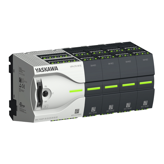
VIPA System MICRO Basics and mounting System conception Basics and mounting 2.1 Safety information for users Handling of electrostatic VIPA modules make use of highly integrated components in MOS-Technology. These sensitive modules components are extremely sensitive to over-voltages that can occur during electrostatic discharges. - Page 11 VIPA System MICRO Basics and mounting System conception Components Extension module Periphery module With the CPU electronic, input/output components and power supply are integrated to one casing. In addition, up to 8 periphery modules of the System MICRO can be con- nected to the backplane bus.
-
Page 12: Dimensions
VIPA System MICRO Basics and mounting Dimensions 2.3 Dimensions Dimensions CPU M13C Dimensions in mm Dimensions extension module EM M09 Dimensions in mm HB400 | CPU | M13-CCF0000 | en | 16-47... -
Page 13: Mounting
VIPA System MICRO Basics and mounting Mounting > Mounting CPU Dimensions periphery module SM M2x Dimensions in mm 2.4 Mounting 2.4.1 Mounting CPU 2.4.1.1 Mounting CPU without mounting rail CAUTION! Mounting without mounting rail is only permitted, if you only want to use the CPU without extension and periphery modules. - Page 14 VIPA System MICRO Basics and mounting Mounting > Mounting CPU Proceeding You can screw the CPU to the back wall by means of screws via the locking levers. The happens with the following proceeding: Dimensions in mm The CPU has a locking lever on the upper and lower side. Pull these levers out- wards as shown in the figure, until these engage 2x audible.
- Page 15 VIPA System MICRO Basics and mounting Mounting > Mounting CPU The CPU has a locking lever on the upper and lower side. Pull these levers out- wards as shown in the figure, until these engage audible. CAUTION! It is not allowed to mount the module sideways on the mounting rail, as otherwise the module may be damaged.
-
Page 16: Mounting The Extension Module
VIPA System MICRO Basics and mounting Mounting > Mounting the extension module 2.4.2 Mounting the extension module Proceeding You have the possibility to extend the interfaces of the CPU by plugging an extension module. For this the extension module is plugged at the left side of the CPU. The mount- ings happens with the following proceeding: Remove the bus cover with a screwdriver on the left side of the CPU. -
Page 17: Mounting Periphery Module
VIPA System MICRO Basics and mounting Mounting > Mounting periphery module 2.4.3 Mounting periphery module Proceeding You have the possibility to extend the periphery area of the CPU by plugging up to 8 periphery modules. For this the periphery modules are plugged at the right side of the CPU. -
Page 18: Wiring
VIPA System MICRO Basics and mounting Wiring > Wiring CPU 2.5 Wiring CAUTION! Consider temperature for external cables! Cables may experience temperature increase due to system heat dissi- pation. Thus the cabling specification must be chosen 5°C above ambient temperature! CAUTION! Separate insulation areas! The system is specified for SELV/PELV environment. - Page 19 VIPA System MICRO Basics and mounting Wiring > Wiring CPU Insert wire The wiring happens without a tool. Determine according to the casing labelling the connection position and insert through the round connection hole of the according contact your prepared wire until it stops, so that it is fixed.
-
Page 20: Wiring Periphery Module
VIPA System MICRO Basics and mounting Wiring > Wiring periphery module Fusing It is recommended to externally protect the electronic power supply for CPU and backplane bus with a 3A fuse (fast) respectively by a line circuit breaker 3A character- istics Z. - Page 21 VIPA System MICRO Basics and mounting Wiring > Wiring periphery module Wiring procedure Labeling on the casing Pin no. at the connector Release area Connection hole for wire Insert wire The wiring happens without a tool. Determine according to the casing labelling the connection position and insert through the round connection hole of the according contact your prepared wire until it stops, so that it is fixed.
-
Page 22: Demounting
VIPA System MICRO Basics and mounting Demounting > Demounting CPU Push the screwdriver backwards: ð The connector is unlocked and can be removed. CAUTION! Via wrong operation such as pressing, the screwdriver down- ward the release lever may be damaged. Plug connector: The connector is plugged by plugging it directly into the release lever. - Page 23 VIPA System MICRO Basics and mounting Demounting > Demounting CPU Ä ‘Option: CPU replacement in a system’ CPU replacement (stand- If more modules are connected to the CPU alone) on page 24. If no other modules are connected to the CPU, the CPU is replaces according to the following proceeding: Pull the locking levers of the CPU outwards until these engage audible.
- Page 24 VIPA System MICRO Basics and mounting Demounting > Demounting CPU Move the CPU on the mounting rail at its position. To fix the CPU at the mounting rail, move the locking levers back to the initial posi- tion. Remove the connectors, which are not necessary at the CPU. Plug again the wired connectors.
- Page 25 VIPA System MICRO Basics and mounting Demounting > Demounting CPU Disconnect all the modules, which are connected to the CPU by moving the CPU along with the extension module on the mounting rail. Remove the CPU with a rotation upwards from the mounting rail. Pull the locking levers of the CPU outwards until these engage audible.
-
Page 26: Demounting The Extension Module
VIPA System MICRO Basics and mounting Demounting > Demounting the extension module Plug again the wired connectors. ð Now you can bring your system back into operation. 2.6.2 Demounting the extension module Proceeding Power-off your system. Remove the corresponding bus connectors. Pull the locking levers of the extension module outwards until these engage audible. -
Page 27: Demounting Periphery Module
VIPA System MICRO Basics and mounting Demounting > Demounting periphery module Reattach the extension module to the CPU by sliding the extension module on the mounting rail to the right until the interface connector slightly locks into the CPU. Move the locking levers back to the initial position. Plug the corresponding bus connectors. - Page 28 VIPA System MICRO Basics and mounting Demounting > Demounting periphery module ... and move the modules accordingly. Remove the periphery module with a rotation upwards from the mounting rail. Pull the locking levers outwards until these engage audible. CAUTION! It is not allowed to mount the module sideways on the mounting rail, as otherwise the module may be damaged! Plug the periphery module from the top onto the mounting rail and turn the periphery module downward until it rests on the mounting rail.
-
Page 29: Installation Guidelines
VIPA System MICRO Basics and mounting Installation guidelines Plug again the wired connectors. ð Now you can bring your system back into operation. 2.7 Installation guidelines General The installation guidelines contain information about the interference free deployment of a PLC system. There is the description of the ways, interference may occur in your PLC, how you can make sure the electromagnetic compatibility (EMC), and how you manage the isolation. - Page 30 VIPA System MICRO Basics and mounting Installation guidelines Basic rules for EMC In the most times it is enough to take care of some elementary rules to guarantee the EMC. Please regard the following basic rules when installing your PLC. Take care of a correct area-wide grounding of the inactive metal parts when installing your components.
-
Page 31: General Data
VIPA System MICRO Basics and mounting General data At stationary operation it is convenient to strip the insulated cable interruption free and lay it on the isolation/protected earth conductor line. To fix the isolation tangles use cable clamps out of metal. The clamps must clasp the isolation extensively and have well contact. - Page 32 VIPA System MICRO Basics and mounting General data Environmental conditions to EN 61131-2 Horizontal installation lying EN 61131-2 0…+60°C Vertical installation EN 61131-2 0…+60°C Air humidity EN 60068-2-30 RH1 (without condensation, rel. humidity 10…95%) Pollution EN 61131-2 Degree of pollution 2 Installation altitude max.
-
Page 33: Hardware Description
VIPA System MICRO Hardware description Properties Hardware description 3.1 Properties M13-CCF0000 SPEED7 technology integrated Programmable via VIPA SPEED7 Studio, Siemens SIMATIC Manager or Siemens TIA Portal 64kbyte work memory integrated (32kbyte code, 32kbyte data) Work memory expandable up to max. 128kbyte (64kbyte code, 64kbyte data) 128kbyte load memory integrated Slot for external storage media (lockable) Status LEDs for operating state and diagnostics... -
Page 34: Structure
VIPA System MICRO Hardware description Structure > System MICRO CPU M13C 3.2 Structure 3.2.1 System MICRO CPU M13C CPU M13-CCF0000 X2: Connector DO (byte 0) X1: Connector DI (byte 0) Slot for external storage media (lockable) Operating mode switch CPU Status bar CPU X3: Ethernet PG/OP channel X4: Ethernet PG/OP channel... -
Page 35: Interfaces
VIPA System MICRO Hardware description Structure > Interfaces 3.2.2 Interfaces HB400 | CPU | M13-CCF0000 | en | 16-47... - Page 36 VIPA System MICRO Hardware description Structure > Interfaces X1: DI byte 0 Function Type Description DI 0.7 Digital input DI 7 / Counter 2 (B) / Frequency 2 * green DI 0.6 green Digital input DI 6 / Counter 2 (A) * DI 0.5 green Digital input DI 5...
- Page 37 VIPA System MICRO Hardware description Structure > Interfaces Function Type Description DO 0.7 green Digital output DO 7 DO 0.6 green Digital output DO 6 DO 0.5 green Digital output DO 5 DO 0.4 green Digital output DO 4 DO 0.3 green Digital output DO 3 / Output channel counter 3 DO 0.2...
- Page 38 VIPA System MICRO Hardware description Structure > Interfaces X5: DI byte 1 Function Type Description reserved reserved DI 1.0 green Digital input DI 8 DI 1.1 Digital input DI 9 / Counter 3 (A) * green DI 1.2 Digital input DI 10 / Counter 3 (B) / Frequency 3 * green DI 1.3 green...
- Page 39 VIPA System MICRO Hardware description Structure > Interfaces Function Type Description Sys DC 24V green 1L+: DC 24V for electronic section supply Sys 0V 1M: GND for electronic section supply Shield Shield AGND GND for analog inputs AI 0 Analog input AI 0 AI 1 Analog input AI 1 DO 1.0...
-
Page 40: Leds
VIPA System MICRO Hardware description Structure > LEDs 3.2.3 LEDs 3.2.3.1 Status bar CPU Description Start-up LED yellow blinks with 1Hz: State of the CPU after PowerON LEDs green are blinking with 2Hz: During the start-up (OB 100) the status bar blinks for at least 3s. Operation LED yellow on: CPU is in STOP state. -
Page 41: Memory Management
VIPA System MICRO Hardware description Structure > Memory management 3.2.3.2 LEDs I/O periphery Digital input Description DI +0.0 DI +0.7 green Digital I+0.0 ... 0.7 has "1" signal Digital I+0.0 ... 0.7 has "0" signal DI +1.0 ... DI +1.7 green Digital input I+1.0 ... -
Page 42: Slot For Storage Media
VIPA System MICRO Hardware description Structure > Operating mode switch 3.2.5 Slot for storage media Overview In this slot you can insert the following storage media: VSD - VIPA SD-Card – External memory card for programs and firmware. VSC - VIPASetCard –... -
Page 43: Option: Extension Module Em M09 2X Serial Interface
VIPA System MICRO Hardware description Option: Extension module EM M09 2x serial interface 3.3 Option: Extension module EM M09 2x serial interface EM M09 X1 PtP (RS422/485) 9pin SubD jack: (isolated) Using the PtP functionality the RS485 interface is allowed to connect via serial point-to- point connection to different source res. -
Page 44: Technical Data
VIPA System MICRO Hardware description Technical data > Technical data CPU LEDs X1 PtP Description green flickers Send activity No send activity X2 MPI(PB) Description green Slave is in DE (data exchange) Slave exchanges data with the master. Slave is in RUN state green blinking Slave CPU is in state start-up. - Page 45 VIPA System MICRO Hardware description Technical data > Technical data CPU Order no. M13-CCF0000 Current consumption from load voltage L+ (without load) 25 mA Rated value DC 24 V Input voltage for signal "0" DC 0...5 V Input voltage for signal "1" DC 15...28.8 V Input voltage hysteresis Frequency range...
- Page 46 VIPA System MICRO Hardware description Technical data > Technical data CPU Order no. M13-CCF0000 Lamp load 10 W Parallel switching of outputs for redundant control of a load not possible Parallel switching of outputs for increased power not possible Actuation of digital input ü...
- Page 47 VIPA System MICRO Hardware description Technical data > Technical data CPU Order no. M13-CCF0000 Resistance inputs Resistance ranges Operational limit of resistor ranges Operational limit of resistor ranges with SFU Basic error limit Basic error limit with SFU Destruction limit resistance inputs Resistance thermometer inputs Resistance thermometer ranges Operational limit of resistance thermometer ranges...
- Page 48 VIPA System MICRO Hardware description Technical data > Technical data CPU Order no. M13-CCF0000 Current consumption from load voltage L+ (without load) Voltage output short-circuit protection Voltage outputs Min. load resistance (voltage range) Max. capacitive load (current range) Max. inductive load (current range) Output voltage ranges Operational limit of voltage ranges Basic error limit voltage ranges with SFU...
- Page 49 VIPA System MICRO Hardware description Technical data > Technical data CPU Order no. M13-CCF0000 Latch input available ü Reset input available Counter output available ü Load and working memory Load memory, integrated 128 KB Load memory, maximum 128 KB Work memory, integrated 64 KB Work memory, maximal 128 KB...
- Page 50 VIPA System MICRO Hardware description Technical data > Technical data CPU Order no. M13-CCF0000 Max. potential difference between Mana and Mintern (Uiso) Max. potential difference between inputs and Mana (Ucm) Max. potential difference between inputs and Mintern (Uiso) Max. potential difference between Mintern and outputs Insulation tested with DC 500 V Command processing times...
- Page 51 VIPA System MICRO Hardware description Technical data > Technical data CPU Order no. M13-CCF0000 Clock synchronization ü Synchronization via MPI Master/Slave Synchronization via Ethernet (NTP) Address areas (I/O) Input I/O address area 2048 Byte Output I/O address area 2048 Byte Input process image maximal 2048 Byte Output process image maximal...
- Page 52 VIPA System MICRO Hardware description Technical data > Technical data CPU Order no. M13-CCF0000 Minimum pulse width 0...0.5 * Period duration Type of output Highside Functionality Sub-D interfaces Type Type of interface RS422/485 isolated Connector Sub-D, 9-pin, female Electrically isolated ü...
- Page 53 VIPA System MICRO Hardware description Technical data > Technical data CPU Order no. M13-CCF0000 Transmission speed, max. 12 Mbit/s Functionality PROFIBUS slave PG/OP channel ü Routing ü S7 communication ü S7 communication as server ü S7 communication as client Direct data exchange (slave-to-slave communication) DPV1 ü...
- Page 54 VIPA System MICRO Hardware description Technical data > Technical data CPU Order no. M13-CCF0000 Type X3/X4 Type of interface Ethernet 10/100 MBit Switch Connector 2 x RJ45 Electrically isolated ü PG/OP channel ü Number of connections, max. Productive connections ü Fieldbus Type Type of interface...
-
Page 55: Technical Data Em M09
VIPA System MICRO Hardware description Technical data > Technical data EM M09 Order no. M13-CCF0000 User data per UDP connection, max. 1472 Byte Housing Material PPE / PPE GF10 Mounting Profile rail 35 mm Mechanical data Dimensions (WxHxD) 72 mm x 88 mm x 71 mm Net weight 221 g Weight including accessories... -
Page 56: Deployment Cpu M13-Ccf0000
VIPA System MICRO Deployment CPU M13-CCF0000 Addressing > Default address assignment of the I/O part Deployment CPU M13-CCF0000 4.1 Assembly Ä Chapter 2 ‘Basics and Information about assembly and cabling mounting’ on page 10. 4.2 Start-up behavior Turn on power supply The CPU checks whether a project AUTOLOAD.WLD exists on the memory card. -
Page 57: Option: Addressing Periphery Modules
VIPA System MICRO Deployment CPU M13-CCF0000 Addressing > Option: Addressing periphery modules Sub module Input address Access Assignment DI24/DO16 BYTE Digital input I+0.0 ... I+0.7 (X1) BYTE Digital input I+1.0 ... I+1.7 (X5) Sub module Input address Access Assignment Counter DINT Channel 0: Counter value / Frequency value DINT... -
Page 58: Hardware Configuration - Cpu
VIPA System MICRO Deployment CPU M13-CCF0000 Hardware configuration - CPU I/O area: 0 ... 127 (default) I/O area max.: 2047 Process image of the inputs (PII): 0 ... 127 Process image of the inputs (PII) max.: 2047 Process image of the outputs (PIQ): 0 ... 127 Process image of the outputs (PIQ) max.: 2047 Max. - Page 59 VIPA System MICRO Deployment CPU M13-CCF0000 Hardware configuration - CPU Installing the IO device The installation of the PROFINET IO devices ‘VIPA MICRO PLC’ happens in the hard- VIPA MICRO PLC ware catalog with the following approach: Go to the service area of www.vipa.com. Load from the download area at ‘PROFINET files’...
-
Page 60: Hardware Configuration - System Micro Modules
VIPA System MICRO Deployment CPU M13-CCF0000 Hardware configuration - System MICRO modules Navigate in the hardware catalog to the directory ‘PROFINET IO è Additional field devices è I/O è VIPA MICRO PLC’ and connect the IO device M13-CCF0000 to your PROFINET system. ð... -
Page 61: Hardware Configuration - Ethernet Pg/Op Channel
VIPA System MICRO Deployment CPU M13-CCF0000 Hardware configuration - Ethernet PG/OP channel 4.6 Hardware configuration - Ethernet PG/OP channel Overview The CPU has an integrated Ethernet PG/OP channel. This channel allows you to pro- gram and remote control your CPU. The Ethernet PG/OP channel (X3/X4) is designed as switch. - Page 62 VIPA System MICRO Deployment CPU M13-CCF0000 Hardware configuration - Ethernet PG/OP channel Assign IP address param- You get valid IP address parameters from your system administrator. The assignment of eters the IP address data happens online in the Siemens SIMATIC Manager starting with ver- sion V 5.3 &...
-
Page 63: Setting Standard Cpu Parameters
VIPA System MICRO Deployment CPU M13-CCF0000 Setting standard CPU parameters > Parameter CPU Transfer your project. Ethernet PG/OP channel 4.7 Setting standard CPU parameters 4.7.1 Parametrization via Siemens CPU Parametrization via Sie- Since the CPU from VIPA is to be configured as Siemens CPU 314C-2 PN/DP mens CPU 314-6EH04 (314-6EH04-0AB0 V3.3) in the Siemens hardware configurator, the standard parameters of the VIPA CPU may be set with "Object properties"... - Page 64 VIPA System MICRO Deployment CPU M13-CCF0000 Setting standard CPU parameters > Parameter CPU Plant designation – Here is the possibility to specify a plant designation for the CPU. – This plant designation identifies parts of the plant according to their function. –...
- Page 65 VIPA System MICRO Deployment CPU M13-CCF0000 Setting standard CPU parameters > Parameter CPU Size of the process image input/output area – Here the size of the process image max. 2048 for the input/output periphery may be fixed (default: 256). OB85 call up at I/O access error –...
-
Page 66: Setting Vipa Specific Cpu Parameters
VIPA System MICRO Deployment CPU M13-CCF0000 Setting VIPA specific CPU parameters Phase offset – Enter the delay time in ms for current execution for the watch dog interrupt. This should be performed if several watchdog interrupts are enabled. – Phase offset allows to distribute processing time for watchdog interrupts across the cycle. - Page 67 VIPA System MICRO Deployment CPU M13-CCF0000 Setting VIPA specific CPU parameters Diagnostics interrupt DO power section supply Diagnostics interrupt DO short circuit/overload VIPA specific parameters The following parameters may be accessed by means of the properties dialog of the VIPA CPU.
-
Page 68: Project Transfer
VIPA System MICRO Deployment CPU M13-CCF0000 Project transfer > Transfer via memory card 4.9 Project transfer Overview There is the following possibility for project transfer into the CPU: Transfer via Ethernet Transfer via memory card Ä Chapter 4.9.3 ‘Option: Transfer via MPI’ on page 69 Option: Transfer via MPI 4.9.1 Transfer via Ethernet Initialization... -
Page 69: Option: Transfer Via Mpi
VIPA System MICRO Deployment CPU M13-CCF0000 Project transfer > Option: Transfer via MPI Copy the wld file at a suited memory card. Plug this into your CPU and start it again. ð The transfer of the application program from the memory card into the CPU takes place depending on the file name after an overall reset or PowerON. -
Page 70: Accessing The Web Server
VIPA System MICRO Deployment CPU M13-CCF0000 Accessing the web server > Structure of the web page Proceeding enabling the A hardware configuration to enable the MPI interface is not necessary. By installing the interface extension module EM M09 the MPI interface is enabled. Turn off the power supply. -
Page 71: Web Page With Selected Cpu
VIPA System MICRO Deployment CPU M13-CCF0000 Accessing the web server > Web page with selected CPU 4.10.3 Web page with selected CPU Info - Overview Here order number, serial number and the version of firmware and hardware of the CPU are listed. - Page 72 VIPA System MICRO Deployment CPU M13-CCF0000 Accessing the web server > Web page with selected CPU VSD... Activated VSD respectively VSC with Informa- tion for the support VSC... VSC-Trial-Time 71:59 Remaining time in hh:mm for deactivation of the expansion memory respectively bus function- ality and the CPU goes to STOP (abnormal operation), if the VSC is removed.
-
Page 73: Operating Modes
VIPA System MICRO Deployment CPU M13-CCF0000 Operating modes > Overview syslibex.wld Protect.wld ARM Processor Load Measurement Cycle Time 100 ms Last Value Maximum Load 100% Data Currently nothing is displayed here. Parameter Currently nothing is displayed here. Here the IP address data of your Ethernet PG/OP channel are shown. 4.11 Operating modes 4.11.1... -
Page 74: Function Security
VIPA System MICRO Deployment CPU M13-CCF0000 Operating modes > Function security Operating mode START- : After PowerON the yellow LED of the status bar blinks in the STOP state. : After a short time the flashing changes to a steady light. During the transition from STOP to RUN a call is issued to the start-up organization block OB 100. -
Page 75: Overall Reset
VIPA System MICRO Deployment CPU M13-CCF0000 Overall reset > Overall reset by means of the operating mode switch Event concerns Effect decentral inputs The inputs are cyclically be read by the decentralized station and the recent values are put at disposal. STOP ®... -
Page 76: Overall Reset By Means Of The Siemens Simatic Manager
VIPA System MICRO Deployment CPU M13-CCF0000 Firmware update 4.12.2 Overall reset by means of the Siemens SIMATIC Manager Proceeding For the following proceeding you must be online connected to your CPU. For an overall reset the CPU must be switched to STOP state. You may place the CPU in STOP by the menu command ‘PLC è... - Page 77 VIPA System MICRO Deployment CPU M13-CCF0000 Firmware update CAUTION! When installing a new firmware you have to be extremely careful. Under certain circumstances you may destroy the CPU, for example if the voltage supply is interrupted during transfer or if the firmware file is defec- tive.
-
Page 78: Reset To Factory Settings
VIPA System MICRO Deployment CPU M13-CCF0000 Reset to factory settings Plug the memory card with the firmware files into the CPU. Please take care of the correct plug-in direction of the memory card. Switch on the power supply. ð After a short boot-up time, the alternate blinking of the red and yellow LED of the status bar shows that at least a more current firmware file was found at the memory card. -
Page 79: Deployment Storage Media - Vsd, Vsc
VIPA System MICRO Deployment CPU M13-CCF0000 Deployment storage media - VSD, VSC Turn power OFF and ON. After a firmware update of the CPU you always should execute a factory reset. 4.15 Deployment storage media - VSD, VSC Overview At the front of the CPU there is a slot for storage media. Here the following storage media can be plugged: VSD - VIPA SD-Card –... - Page 80 VIPA System MICRO Deployment CPU M13-CCF0000 Deployment storage media - VSD, VSC VSDs are external storage media based on SD memory cards. VSDs are pre-formatted with the PC format FAT 16 (max. 2GB) and can be accessed via a card reader. After PowerON respectively an overall reset the CPU checks, if there is a VSD with data valid for the CPU.
-
Page 81: Extended Know-How Protection
VIPA System MICRO Deployment CPU M13-CCF0000 Extended know-how protection Accessing the storage To the following times an access takes place on a storage medium: medium After overall reset The CPU checks if a VSC is inserted. If so, the corresponding optional functions are enabled. -
Page 82: Cmd - Auto Commands
VIPA System MICRO Deployment CPU M13-CCF0000 CMD - auto commands Ä Chapter 4.12 Plug the memory card into the CPU and execute an overall reset. ‘Overall reset’ on page 75 ð The overall reset stores the blocks in protect.wld permanently in the CPU pro- tected from accesses of 3. - Page 83 VIPA System MICRO Deployment CPU M13-CCF0000 CMD - auto commands Command Description Diagnostics entry SAVE_PROJECT The recent project (blocks and hardware configuration) is stored 0xE806 as "s7prog.wld" at the memory card. If the file just exists it is renamed to "s7prog.old". If your CPU is password protected so you have to add this as parameter.
-
Page 84: Control And Monitoring Of Variables With Test Functions
VIPA System MICRO Deployment CPU M13-CCF0000 Control and monitoring of variables with test functions The parameters IP address, subnet mask and gateway may be received from the system administrator. Enter the IP address if there is no gateway used. 4.18 Control and monitoring of variables with test functions Overview For troubleshooting purposes and to display the status of certain variables you can... -
Page 85: Diagnostic Entries
VIPA System MICRO Deployment CPU M13-CCF0000 Diagnostic entries ‘PLC This test function returns the condition of a selected operand (inputs, outputs, flags, data è Monitor/Modify word, counters or timers) at the end of program execution. This information is obtained Variables’ from the corresponding area of the selected operands. -
Page 86: Deployment I/O Periphery
VIPA System MICRO Deployment I/O periphery Overview Deployment I/O periphery 5.1 Overview Project engineering and On this CPU the connectors for digital respectively analog signal and Technological parametrization functions are combined in a one casing. The project engineering happens in the Siemens SIMATIC Manager as Siemens CPU 314C-2 PN/DP (314-6EH04-0AB0 V3.3). -
Page 87: Address Assignment
VIPA System MICRO Deployment I/O periphery Analog input > Properties 5.2 Address assignment Sub module Input address Access Assignment AI5/AO2 WORD Analog input channel 0 (X6) WORD Analog input channel 1 (X6) Sub module Input address Access Assignment DI24/DO16 BYTE Digital input I+0.0 ... -
Page 88: Analog Value Representation
VIPA System MICRO Deployment I/O periphery Analog input > Analog value representation 5.3.2 Analog value representation Number representation in Siemens S7 format Resolu- Analog value - twos complement tion High byte (byte 0) Low byte (byte 1) Bit number Value 11Bit+sign Measuring value *) The lowest value irrelevant bits of the output value (0) are marked with "X". -
Page 89: Wiring
VIPA System MICRO Deployment I/O periphery Analog input > Parametrization 5.3.3 Wiring X6: DC 24V, AI, DO byte 1 Function Type Description Sys DC 24V green 1L+: DC 24V for electronic section supply Sys 0V 1M: GND for electronic section supply Shield Shield AGND... -
Page 90: Digital Input
VIPA System MICRO Deployment I/O periphery Digital input > Properties 5.3.4.2 Filter Parameter hardware con- The analog input part has a filter integrated. The parametrization of the filter happens in figuration the Siemens SIMATIC Manager via the parameter ‘Integration time’ . The default value of the filter is 1000ms. -
Page 91: Wiring
VIPA System MICRO Deployment I/O periphery Digital input > Wiring 5.4.2 Wiring X1: DI byte 0 Function Type Description DI 0.7 green Digital input DI 7 / Counter 2 (B) / Frequency 2 * DI 0.6 green Digital input DI 6 / Counter 2 (A) * DI 0.5 green Digital input DI 5... -
Page 92: Parametrization
VIPA System MICRO Deployment I/O periphery Digital input > Parametrization Function Type Description reserved reserved DI 1.0 Digital input DI 8 green DI 1.1 green Digital input DI 9 / Counter 3 (A) * DI 1.2 green Digital input DI 10 / Counter 3 (B) / Frequency 3 * DI 1.3 green Digital input DI 11 / Gate 3 *... -
Page 93: Status Indication
VIPA System MICRO Deployment I/O periphery Digital input > Status indication 5.4.4 Status indication Function Type Description DI 0.7 green Digital input DI 7 / Counter 2 (B) / Frequency 2 * DI 0.6 Digital input DI 6 / Counter 2 (A) * green DI 0.5 Digital input DI 5... -
Page 94: Digital Output
VIPA System MICRO Deployment I/O periphery Digital output > Wiring Power supply Description green DC 24V electronic section supply DC 24V electronic section supply not available green DC 24V power section supply inputs OK DC 24V power section supply inputs not available green DC 24V power section supply outputs OK DC 24V power section supply outputs not available... -
Page 95: Parametrization
VIPA System MICRO Deployment I/O periphery Digital output > Status indication Function Type Description DO 0.7 green Digital output DO 7 DO 0.6 green Digital output DO 6 DO 0.5 green Digital output DO 5 DO 0.4 green Digital output DO 4 DO 0.3 green Digital output DO 3 / Output channel counter 3... -
Page 96: Counting
VIPA System MICRO Deployment I/O periphery Counting > Wiring Digital output Description DO +0.0 ... DO +0.7 green Digital output Q+0.0 ... 0.7 has "1" signal Digital output Q+0.0 ... 0.7 has "0" signal DO +1.0 ... DO +1.3 green Digital output Q+1.0 ... - Page 97 VIPA System MICRO Deployment I/O periphery Counting > Wiring Function Type Description DI 0.7 green Digital input DI 7 / Counter 2 (B) / Frequency 2 * DI 0.6 green Digital input DI 6 / Counter 2 (A) * DI 0.5 green Digital input DI 5 DI 0.4...
- Page 98 VIPA System MICRO Deployment I/O periphery Counting > Wiring Input signals The following sensors can be connected 24V incremental encoders with two phase-shifted by 90° tracks 24V pulse encoder with direction signal 24V initiator as BERO or beam sensor For not all inputs are available at the same time, for every counter you may define the input assignment via the parameterization for the following input signals: Counter –...
-
Page 99: Proceeding
VIPA System MICRO Deployment I/O periphery Counting > Parametrization Output channel Counter Every counter has an assigned output channel. For each counter you can specify the behavior of the counter output via the parametrization with ‘Characteristics of the output’ Ä Chapter 5.6.4.4 ‘Counter’ on page 100 and ‘Pulse duration’... - Page 100 VIPA System MICRO Deployment I/O periphery Counting > Parametrization Sub module Output address Access Assignment Counter DWORD reserved DWORD reserved DWORD reserved DWORD reserved 5.6.4.2 Interrupt selection Via ‘Basic parameters’ you can reach ‘Select interrupt’ . Here you can define the inter- rupts the CPU will trigger.
- Page 101 VIPA System MICRO Deployment I/O periphery Counting > Parametrization Parameter overview Operating parameters Description Assignment Main count direction None No restriction of the counting range None Up: Restricts the up-counting range. The counter starts from 0 or load value, counts in positive direction up to the declaration end value -1 and then jumps back to load value at the next positive transducer pulse.
- Page 102 VIPA System MICRO Deployment I/O periphery Counting > Parametrization Input Description Assignment Signal evaluation Specify the signal of the connected encoder: Pulse/direction Pulse/direction At the input count and direction signal are connected At the input there is an encoder connected with the fol- lowing evaluation: –...
- Page 103 VIPA System MICRO Deployment I/O periphery Counting > Parametrization Hardware interrupt Description Assignment Hardware gate opening Hardware interrupt by edge 0-1 exclusively at HW gate disabled channel 3 enabled: Process interrupt by edge 0-1 exclusively at HW gate channel 3 with open SW gate disabled: no hardware interrupt Hardware gate closing Hardware interrupt by edge 1-0 exclusively at HW gate...
-
Page 104: Counter Operating Modes
VIPA System MICRO Deployment I/O periphery Counting > Counter operating modes 5.6.5 Counter operating modes 5.6.5.1 Count continuously In this operating mode the counter counts starting with the load value. When the counter counts forward and reaches the upper count limit and another counting pulse in positive direction arrives, it jumps to the lower count limit and counts from there on. - Page 105 VIPA System MICRO Deployment I/O periphery Counting > Counter operating modes 5.6.5.2 Count once 5.6.5.2.1 No main counting direction The counter counts once starting with load value. It is counted forward or backward. The counter limits are fix set to maximum range. At over- or underflow at the count limits, the counter jumps to the according other count limit and the gate is automatically closed.
- Page 106 VIPA System MICRO Deployment I/O periphery Counting > Counter operating modes 5.6.5.2.2 Main counting direction forward The counter counts forward starting with the load value. When the counter reaches the End value -1 in positive direction, it jumps to the load value at the next count pulse and the gate is automatically closed.
- Page 107 VIPA System MICRO Deployment I/O periphery Counting > Counter operating modes 5.6.5.2.3 Main counting direction backward The counter counts backward starting with the load value. When the counter reaches the End value +1 in positive direction, it jumps to the load value at the next count pulse and the gate is automatically closed.
- Page 108 VIPA System MICRO Deployment I/O periphery Counting > Counter operating modes 5.6.5.3 Count periodically 5.6.5.3.1 No main counting direction The counter counts forward or backwards starting with the load value. At over- or underrun at the count limits, the counter jumps to the load value and con- tinues counting.
- Page 109 VIPA System MICRO Deployment I/O periphery Counting > Counter operating modes 5.6.5.3.2 Main counting direction forward The counter counts forward starting with the load value. When the counter reaches the end value -1 in positive direction, it jumps to the load value at the next positive count pulse and continues counting.
- Page 110 VIPA System MICRO Deployment I/O periphery Counting > Counter operating modes 5.6.5.3.3 Main counting direction backward Main counting direction backward The counter counts backward starting with the load value. When the counter reaches the end value +1 in positive direction, it jumps to the load value at the next negative count pulse and continues counting.
-
Page 111: Counter - Additional Functions
VIPA System MICRO Deployment I/O periphery Counting > Counter - Additional functions 5.6.6 Counter - Additional functions 5.6.6.1 Overview Schematic structure The illustration shows how the additional functions influence the counting behavior. The following pages describe these additional functions in detail: 5.6.6.2 Gate function Function... - Page 112 VIPA System MICRO Deployment I/O periphery Counting > Counter - Additional functions At interrupt function, the counter starts counting with the last recent counter value after gate restart. Counter 0 ... 2 SW gate Gate function Reaction counter 0 ... 2 Edge 0-1 Abort count process Restart with load value...
- Page 113 VIPA System MICRO Deployment I/O periphery Counting > Counter - Additional functions 5.6.6.4 Additional functions counter 3 Exclusively counter 3 has the following additional functions: HW gate via Gate 3 Latch function 5.6.6.4.1 HW gate via Gate 3 Starting, stopping and interrupting a count function of counter 3 happens via the internal gate (I gate).
- Page 114 VIPA System MICRO Deployment I/O periphery Counting > Counter - Additional functions 5.6.6.5 Counter output channel Characteristics of the Each counter has an output channel. You pre-define the behavior of the counter output output via the parametrization: no comparison: – The output is used as normal output.
- Page 115 VIPA System MICRO Deployment I/O periphery Counting > Counter - Additional functions ³ Effect at counter value comparison value Counter value ³ comparison value ® output is set and hysteresis activated Leave hysteresis range ® output is reset Counter value ³ comparison value ® output is set and hysteresis activated Leave hysteresis range, output remains set for counter value ³...
- Page 116 VIPA System MICRO Deployment I/O periphery Counting > Counter - Additional functions Counter value = comparison value ® output is set and hysteresis activated Output is reset for leaving hysteresis range and counter value > comparison value Counter value = comparison value ® output is set and hysteresis activated Counter value = comparison value and hysteresis active ®...
-
Page 117: Diagnostics And Interrupt
VIPA System MICRO Deployment I/O periphery Frequency measurement > Properties 5.6.7 Diagnostics and interrupt Overview GSDML Edge at an digital interrupt input Via the hardware configuration you can define the following trigger for a hardware inter- rupt that can trigger a diagnostics interrupt: Reaching the comparison value Overflow respectively at overrun upper counter limit Underflow respectively at underrun lower counter limit... -
Page 118: Wiring
VIPA System MICRO Deployment I/O periphery Frequency measurement > Wiring Integration time Counting pulse SW gate Evaluated frequency The counting function is disabled during the pulse width modulation on the same channel. 5.7.2 Wiring 5.7.2.1 Frequency measurement inputs Connect the signal to be measured at input B of the corresponding counter. X1: DI byte 0 HB400 | CPU | M13-CCF0000 | en | 16-47... - Page 119 VIPA System MICRO Deployment I/O periphery Frequency measurement > Wiring Function Type Description DI 0.7 green Digital input DI 7 / Counter 2 (B) / Frequency 2 * DI 0.6 green Digital input DI 6 / Counter 2 (A) * DI 0.5 green Digital input DI 5...
-
Page 120: Proceeding
VIPA System MICRO Deployment I/O periphery Frequency measurement > Parametrization 5.7.3 Proceeding Hardware configuration In the Siemens SIMATIC Manager the following steps should be executed: Perform a hardware configuration for the CPU. Ä Chapter 4.4 ‘Hardware configura- tion - CPU’ on page 58 Double-click the counter sub module of the CPU 314C-2 PN/DP. - Page 121 VIPA System MICRO Deployment I/O periphery Frequency measurement > Parametrization 5.7.4.3 Operating mode per channel Parameter hardware con- Select via ‘Channel’ the channel select via ‘Operating’ the operating mode. The fol- figuration lowing operating modes are supported: Not parameterized: Channel is deactivated Ä...
-
Page 122: Status Indication
VIPA System MICRO Deployment I/O periphery Frequency measurement > Status indication 5.7.5 Status indication Function Type Description DI 0.7 green Digital input DI 7 / Counter 2 (B) / Frequency 2 * DI 0.6 Digital input DI 6 / Counter 2 (A) * green DI 0.5 Digital input DI 5... -
Page 123: Pulse Width Modulation - Pwm
VIPA System MICRO Deployment I/O periphery Pulse width modulation - PWM > Properties Power supply Description green DC 24V electronic section supply DC 24V electronic section supply not available green DC 24V power section supply inputs OK DC 24V power section supply inputs not available green DC 24V power section supply outputs OK DC 24V power section supply outputs not available... -
Page 124: Wiring
VIPA System MICRO Deployment I/O periphery Pulse width modulation - PWM > Proceeding 5.8.2 Wiring 5.8.2.1 Pulse width modulation outputs X2: DO byte 0 Function Type Description DO 0.7 Digital output DO 7 green DO 0.6 Digital output DO 6 green DO 0.5 green... -
Page 125: Parametrization
VIPA System MICRO Deployment I/O periphery Pulse width modulation - PWM > Parametrization User program The SFB 49 should cyclically be called (e.g. OB 1) for controlling the pulse width modulation. The SFB is to be called with the corresponding instance DB. Here the parameters of the SFB are stored. - Page 126 VIPA System MICRO Deployment I/O periphery Pulse width modulation - PWM > Parametrization Period On-delay Pulse duration Pulse pause Parameter overview Operating parameters Description Assignment Output format Here specify the range of values for the output. The CPU Per mil hereby determines the pulse duration: Per mil –...
-
Page 127: Status Indication
VIPA System MICRO Deployment I/O periphery Pulse width modulation - PWM > Status indication Operating parameters Description Assignment Period With the period you define the length of the output 20000 sequence, which consists of pulse duration and pulse pause. Range of values: Time base 1ms: 1 ... -
Page 128: Diagnostic And Interrupt
VIPA System MICRO Deployment I/O periphery Diagnostic and interrupt > Process interrupt 5.9 Diagnostic and interrupt 5.9.1 Overview Hardware interrupt The parametrization allows you to define the following trigger for a hardware interrupt: Edge at an digital interrupt input Reaching the comparison value Overflow respectively at overrun upper counter limit Underflow respectively at underrun lower counter limit Opening the HW gate with open SW gate - except for counter 3... - Page 129 VIPA System MICRO Deployment I/O periphery Diagnostic and interrupt > Process interrupt Local double word 8 of OB 40 at Alarm Inputs Local byte Bit 7...0 Bit 0: Edge at I+0.0 Bit 1: Edge at I+0.1 Bit 2: Edge at I+0.2 Bit 3: Edge at I+0.3 Bit 4: Edge at I+0.4 Bit 5: Edge at I+0.5...
- Page 130 VIPA System MICRO Deployment I/O periphery Diagnostic and interrupt > Process interrupt Local byte Bit 7...0 Bit 1, 0: reserved Bit 2: Over-/underflow/end value counter 0 Bit 3: Counter 0 reached comparison value Bit 5, 4: reserved Bit 6: Over-/underflow/ end value counter 1 Bit 7: Counter 1 reached comparison value Bit 1, 0: reserved Bit 2: Over-/underflow/end value counter 2...
-
Page 131: Diagnostic Interrupt
VIPA System MICRO Deployment I/O periphery Diagnostic and interrupt > Diagnostic interrupt 5.9.3 Diagnostic interrupt Function An interrupt for the corresponding channel operating mode can only be triggered if you have additionally parameterized ‘Diagnostics+Process’ at ‘Select interrupt’ of the ‘Basic parameters’ . Via the parameterization (record set 7Fh) you may activate a global diagnostic interrupt for the module. - Page 132 VIPA System MICRO Deployment I/O periphery Diagnostic and interrupt > Diagnostic interrupt Record set 0 Diag- Byte Bit 7...0 nostic incoming Bit 0: set at module failure – Counter/Frequency measurement: Process interrupt lost – Digital input: Process interrupt lost – Missing power supply DI or DO –...
- Page 133 VIPA System MICRO Deployment I/O periphery Diagnostic and interrupt > Diagnostic interrupt Byte Bit 7...0 Bit 0: set at module failure – Counter/Frequency measurement: Process interrupt lost – Digital input: Process interrupt lost – Missing power supply DI or DO –...
- Page 134 VIPA System MICRO Deployment I/O periphery Diagnostic and interrupt > Diagnostic interrupt Byte Bit 7...0 Bit 0: Error in channel group 0 (I+0.0 ... I+0.3) Bit 1: Error in channel group 1 (I+0.4 ... I+0.7) Bit 2: Error in channel group 2 (I+1.0 ... I+1.3) Bit 3: Error in channel group 2 (I+1.4 ...
- Page 135 VIPA System MICRO Deployment I/O periphery Diagnostic and interrupt > Diagnostic interrupt Byte Bit 7...0 Ä ‘Record set 0 Diagnostic 0 ... 3 Content record set 0 ’ on page 132 incoming Bit 6 ... 0: Channel type (here 70h) –...
- Page 136 VIPA System MICRO Deployment I/O periphery Diagnostic and interrupt > Diagnostic interrupt Byte Bit 7...0 Diagnostic interrupt due to "process interrupt lost" at... Bit 0: ... input I+1.4 Bit 1: 0 (fix) Bit 2: ... input I+1.5 Bit 3: 0 (fix) Bit 4: ...
- Page 137 VIPA System MICRO Deployment I/O periphery Diagnostic and interrupt > Diagnostic interrupt Byte Bit 7...0 Ä ‘Record set 0 Diagnostic 0 ... 3 Content record set 0 ’ on page 132 incoming Bit 6 ... 0: Channel type (here 70h) –...
- Page 138 VIPA System MICRO Deployment I/O periphery Diagnostic and interrupt > Diagnostic interrupt Byte Bit 7...0 Diagnostic interrupt due to "process interrupt lost" at... Bit 0: ... input I+1.4 Bit 1: 0 (fix) Bit 2: ... input I+1.5 Bit 3: 0 (fix) Bit 4: ...
- Page 139 VIPA System MICRO Deployment I/O periphery Diagnostic and interrupt > Diagnostic interrupt Byte Bit 7...0 Bit 0: Error in channel group 0 (I+0.0 ... I+0.3) Bit 1: Error in channel group 1 (I+0.4 ... I+0.7) Bit 2: Error in channel group 2 (I+1.0 ... I+1.3) Bit 3: Error in channel group 3 (I+1.4 ...
-
Page 140: Deployment Pg/Op Communication - Productive
VIPA System MICRO Deployment PG/OP communication - productive Basics - Industrial Ethernet in automation Deployment PG/OP communication - productive 6.1 Basics - Industrial Ethernet in automation Overview The flow of information in a company presents a vast spectrum of requirements that must be met by the communication systems. -
Page 141: Basics - Iso/Osi Reference Model
VIPA System MICRO Deployment PG/OP communication - productive Basics - ISO/OSI reference model 6.2 Basics - ISO/OSI reference model Overview The ISO/OSI reference model is based on a proposal that was developed by the Interna- tional Standards Organization (ISO). This represents the first step towards an interna- tional standard for the different protocols. -
Page 142: Basics - Terms
VIPA System MICRO Deployment PG/OP communication - productive Basics - Terms Layer 5 - Session layer The session layer is also called the communication control layer. It relieves the communi- cation between service deliverer and the requestor by establishing and holding the con- nection if the transport system has a short time fail out. -
Page 143: Basics - Protocols
VIPA System MICRO Deployment PG/OP communication - productive Basics - Protocols 6.4 Basics - Protocols Overview Protocols define a set of instructions or standards that enable computer to establish com- munication connections and exchange information as error free as possible. A commonly established protocol for the standardization of the complete computer communication is the so called ISO/OSI layer model, a model based upon seven layers with rules for the Ä... -
Page 144: Basics - Ip Address And Subnet
VIPA System MICRO Deployment PG/OP communication - productive Basics - IP address and subnet Open communication In the ‘open communication’ the communication takes place via the user program by means of handling blocks. These blocks are also part of the Siemens SIMATIC Manager. You will find these in the ‘Standard Library’... - Page 145 VIPA System MICRO Deployment PG/OP communication - productive Basics - IP address and subnet Subnet mask binary all "1" binary all "0" IPv4 address Net-ID Host-ID Subnet mask and IPv4 address Net-ID Subnet-ID new Host-ID Address at first start-up At the first start-up of the CPU, the Ethernet PG/OP channel does not have an IP address.
-
Page 146: Fast Introduction
VIPA System MICRO Deployment PG/OP communication - productive Hardware configuration Never choose an IP address with Host-ID=0 or Host-ID=maximum! (e.g. for class B with subnet mask = 255.255.0.0, the "172.16.0.0" is reserved and the "172.16.255.255" is occupied as local broadcast address for this network.) 6.6 Fast introduction Overview... -
Page 147: Configure Siemens S7 Connections
VIPA System MICRO Deployment PG/OP communication - productive Configure Siemens S7 connections 6.8 Configure Siemens S7 connections Overview The project engineering of connections i.e. the "link-up" between stations happens in NetPro from Siemens. NetPro is a graphical user interface for the link-up of stations. A communication connection enables the program controlled communication between two participants at the Industrial Ethernet. - Page 148 VIPA System MICRO Deployment PG/OP communication - productive Configure Siemens S7 connections Work environment of For the project engineering of connections, a thorough knowledge with NetPro from Sie- NetPro mens is required! The following passage only describes the basic usage of NetPro. More detailed information about NetPro is to be found in the according online manual res.
- Page 149 VIPA System MICRO Deployment PG/OP communication - productive Configure Siemens S7 connections Projecting connections Projecting connections For the project engineering of connections, open the connection list by selecting the according CPU. Choose Insert new connection in the context menu: Connection partner (partner station) A dialog window opens where you may choose the connection partner and the connection type.
- Page 150 VIPA System MICRO Deployment PG/OP communication - productive Configure Siemens S7 connections Connection types With this CPU exclusively Siemens S7 connection may be configured with Siemens NetPro. Siemens S7 connection For data transfer with Siemens S7 connections the FB/SFB VIPA handling blocks are necessary;...
- Page 151 VIPA System MICRO Deployment PG/OP communication - productive Configure Siemens S7 connections In the following every relevant parameter of a Siemens S7 connection is described: Local connection end point: Here you may define how the connection is to be established. Since the Siemens SIMATIC Manager can identify the communication options by means of the end points, some options are already preset and may not be changed.
-
Page 152: Configure Open Communication
VIPA System MICRO Deployment PG/OP communication - productive Configure Open Communication Function blocks FB/SFB Label Description FB/SFB 12 BSEND Sending data in blocks: FB/SFB 12 BSEND sends data to a remote partner FB/SFB of the type BRCV (FB/SFB 13). The data area to be transmitted is segmented. Each segment is sent individually to the partner. - Page 153 VIPA System MICRO Deployment PG/OP communication - productive Configure Open Communication UDTs Designation Connection-oriented protocols: Connectionless protocol: UDP TCP native as per RFC 793, ISO according to RFC 768 on TCP as per RFC 1006 UDT 65* TCON_PAR Data structure for assigning connec- Data structure for assigning parameters tion parameters for the local communications access point...
- Page 154 VIPA System MICRO Deployment PG/OP communication - productive Configure Open Communication The following connection-oriented protocols are supported with FBs for open communica- tion via Industrial Ethernet: TCP/IP native according to RFC 793 (connection types 01h and 11h): – During data transmission, no information about the length or about the start and end of a message is transmitted.
-
Page 155: Option: Ptp Communication
VIPA System MICRO Option: PtP communication Fast introduction Option: PtP communication 7.1 Fast introduction General For the PtP communication the use of the optionally available extension module EM M09 is required. The extension module provides interface X1: PtP (RS422/485) with fixed pin Ä... -
Page 156: Principle Of The Data Transfer
VIPA System MICRO Option: PtP communication Principle of the data transfer 7.2 Principle of the data transfer RS485 PtP communication The data transfer is handled during runtime by using FC/SFCs. The principle of data transfer is the same for all protocols and is shortly illustrated in the following. Data, which are written into the according data channel by the CPU, is stored in a FIFO send buffer (first in first out) with a size of 2x1024byte and then put out via the interface. -
Page 157: Ptp Communication Via Extension Module Em M09
VIPA System MICRO Option: PtP communication PtP communication via extension module EM M09 7.3 PtP communication via extension module EM M09 X1 PtP (RS422/485) 9pin SubD jack: (isolated) Using the PtP functionality the RS485 interface is allowed to connect via serial point-to- point connection to different source res. - Page 158 VIPA System MICRO Option: PtP communication PtP communication via extension module EM M09 RS485 cabling with PROFIBUS cable X1 PtP interface Periphery Never connect the cable shield and the M5V (pin 5) together, due to the compensation currents the interfaces could be destroyed! HB400 | CPU | M13-CCF0000 | en | 16-47...
- Page 159 VIPA System MICRO Option: PtP communication PtP communication via extension module EM M09 RS485 cabling with For isolated interfaces you have 5V (P5V) isolated at pin 6 and the corresponding ground defined static voltage (M5V) at pin 5. With this isolated voltage, you can assign defined static voltage levels to levels the signal lines and so ensure a low reflection level.
-
Page 160: Parametrization
VIPA System MICRO Option: PtP communication Parametrization > FC/SFC 216 - SER_CFG - Parametrization PtP RS422 cabling with For isolated interfaces you have 5V (P5V) isolated at pin 6 and the corresponding ground defined static voltage (M5V) at pin 5. With this isolated voltage, you can assign defined static voltage levels to levels the signal lines and so ensure a low reflection level. -
Page 161: Communication
VIPA System MICRO Option: PtP communication Protocols and procedures 7.5 Communication 7.5.1 FC/SFC 217 - SER_SND - Send to PtP This block sends data via the serial interface. The repeated call of the FC/SFC 217 SER_SND delivers a return value for 3964R, USS and Modbus via RETVAL that con- tains, among other things, recent information about the acknowledgement of the partner station. - Page 162 VIPA System MICRO Option: PtP communication Protocols and procedures As Start-res. End-ID all Hex values from 01h to 1Fh are permissible. Characters above 1Fh are ignored. In the user data, characters below 20h are not allowed and may cause errors. The number of Start- and End-IDs may be different (1 Start, 2 End res. 2 Start, 1 End or other combinations).
- Page 163 VIPA System MICRO Option: PtP communication Protocols and procedures The following features characterize the USS protocol: Multi point connection Master slave access procedure Single master system Max. 32 participants Simple and secure telegram frame It is essential: You may connect 1 master and max. 31 slaves at the bus The single slaves are addressed by the master via an address sign in the telegram.
-
Page 164: Modbus - Function Codes
VIPA System MICRO Option: PtP communication Modbus - Function codes Modbus The Modbus protocol is a communication protocol that fixes a hierarchic structure with one master and several slaves. Physically, Modbus works with a serial half-duplex connection. There are no bus con- flicts occurring, because the master can only communicate with one slave at a time. - Page 165 VIPA System MICRO Option: PtP communication Modbus - Function codes For the CPs from VIPA is not differentiating digital and analog data, the following assign- ment is valid: 0x - Bit area for master output data Access via function code 01h, 05h, 0Fh 1x - Bit area for master input data Access via function code 02h 3x - word area for master input data...
- Page 166 VIPA System MICRO Option: PtP communication Modbus - Function codes Respond of the slave If the slave announces an error, the function code is send back with an "ORed" 80h. Without an error, the function code is sent back. ® Error Slave answer: Function code OR 80h ®...
- Page 167 VIPA System MICRO Option: PtP communication Modbus - Function codes Command telegram Slave address Function code Address 1. bit Number of words Check sum CRC/LRC 1byte 1byte 1word 1word 1word Respond telegram Slave address Function code Number of Data 1. word Data 2.
- Page 168 VIPA System MICRO Option: PtP communication Modbus - Function codes Please regard that the number of bits has additionally to be set in byte. Command telegram Slave Function Address 1. Number of Number of Data 1. Data 2. Check sum address code bits...
-
Page 169: Option: Deployment Profibus Communication
VIPA System MICRO Option: Deployment PROFIBUS communication PROFIBUS communication Option: Deployment PROFIBUS communication 8.1 Fast introduction Overview For the PROFIBUS communication the use of the optionally available extension module EM M09 is required. The extension module provides interface X2: MPI(PB) with fixed pin Ä... -
Page 170: Profibus Communication Via Extension Module Em M09
VIPA System MICRO Option: Deployment PROFIBUS communication PROFIBUS communication via extension module EM M09 Operating mode DP slave: There is the possibility to enable the option ‘Test, commissioning, routing’ in the hard- Test, commissioning, ware configuration by means of the properties dialog of the PROFIBUS via the register routing (active/passive) ‘Operating mode’... - Page 171 VIPA System MICRO Option: Deployment PROFIBUS communication PROFIBUS communication via extension module EM M09 Switch on the power supply. ð After a short boot time the interface X2 MPI(PB) is ready for MPI communica- tion with the MPI address 2. To switch the interface X2 MPI(PB) to PROFIBUS functionality you have to activate the according bus functionality by means of a VSC storage media from VIPA.
-
Page 172: Deployment As Profibus Dp Slave
VIPA System MICRO Option: Deployment PROFIBUS communication Deployment as PROFIBUS DP slave 8.4 Deployment as PROFIBUS DP slave Fast introduction In the following the deployment of the PROFIBUS section as "intelligent" DP slave on master system is described, which exclusively may be configured in the Siemens SIMATIC Manager. - Page 173 VIPA System MICRO Option: Deployment PROFIBUS communication Deployment as PROFIBUS DP slave Open the properties dialog of the DP interface of the CPU by means of a double- click at ‘MPI/DP’ . Set Interface: type to "PROFIBUS". Connect to PROFIBUS and preset an address (e.g. 2) and confirm with [OK]. Switch at Operating mode to "DP master"...
-
Page 174: Profibus Installation Guidelines
VIPA System MICRO Option: Deployment PROFIBUS communication PROFIBUS installation guidelines 8.5 PROFIBUS installation guidelines PROFIBUS in general A PROFIBUS DP network may only be built up in linear structure. PROFIBUS DP consists of minimum one segment with at least one master and one slave. - Page 175 VIPA System MICRO Option: Deployment PROFIBUS communication PROFIBUS installation guidelines The PROFIBUS line has to be terminated with its ripple resistor. Please make sure to terminate the last participants on the bus at both ends by activating the terminating resistor. EasyConn bus connector In PROFIBUS all participants are wired parallel.
-
Page 176: Commissioning And Start-Up Behavior
VIPA System MICRO Option: Deployment PROFIBUS communication Commissioning and Start-up behavior Wiring [1] 1./last bus participant [2] further participants CAUTION! The terminating resistor is only effective, if the connector is installed at a bus participant and the bus participant is connected to a power supply. The tightening torque of the screws to fix the connector to a device must not exceed 0.02Nm! A complete description of installation and deployment of the terminating... - Page 177 VIPA System MICRO Option: Deployment PROFIBUS communication Commissioning and Start-up behavior Online with bus parameter The DP master can be served with bus parameters by means of a hardware configura- without slave project tion. As soon as these are transferred the DP master goes online with his bus parameter. This is shown by the status bar.
-
Page 178: Configuration With Vipa Speed7 Studio
VIPA System MICRO Configuration with VIPA SPEED7 Studio SPEED7 Studio - Overview Configuration with VIPA SPEED7 Studio 9.1 SPEED7 Studio - Overview SPEED7 Studio - Working In this part the project engineering of the VIPA CPU in the VIPA SPEED7 Studio is environment shown. -
Page 179: Speed7 Studio - Work Environment
VIPA System MICRO Configuration with VIPA SPEED7 Studio SPEED7 Studio - Work environment End SPEED7 Studio Select one of the following options if you want to end the program: Main window: Click on the Close button of the SPEED7 Studio program window. - Page 180 VIPA System MICRO Configuration with VIPA SPEED7 Studio SPEED7 Studio - Work environment (1) Menu bar Most of the commands you need for working with SPEED7 Studio are provided in the menu bar. Further commands can be accessed via the context menus using the right mouse button, e.g.
-
Page 181: Project Tree
VIPA System MICRO Configuration with VIPA SPEED7 Studio SPEED7 Studio - Work environment > Project tree 9.2.1 Project tree (1) Title and author (2) Project (3) Documentation (4) PLC (5) Motion Control (6) PLC program (7) Local components (8) Field periphery (9) HMI In the project tree, you can access commands in order to add or delete objects, e.g. -
Page 182: Catalog
VIPA System MICRO Configuration with VIPA SPEED7 Studio SPEED7 Studio - Work environment > Catalog 9.2.2 Catalog (1) Switching to another view (2) Register (3) Show/hide objects (4) Search (5) Filter (6) Objects (7) Catalog information Devices and components which you want to add to the project can be selected in the cat- alog. - Page 183 VIPA System MICRO Configuration with VIPA SPEED7 Studio SPEED7 Studio - Work environment > Catalog (4) Search You can search for certain objects in the catalog. Enter a search text in the input field. ð Only those objects are displayed in the catalog which contain the search text. Click on to delete the search text.
-
Page 184: Speed7 Studio - Hardware Configuration - Cpu
VIPA System MICRO Configuration with VIPA SPEED7 Studio SPEED7 Studio - Hardware configuration - Ethernet PG/OP channel 9.3 SPEED7 Studio - Hardware configuration - CPU Precondition For project engineering a thorough knowledge of the SPEED7 Studio is required! Proceeding Start the SPEED7 Studio. Create a new project in the Work area with ‘New project’... - Page 185 VIPA System MICRO Configuration with VIPA SPEED7 Studio SPEED7 Studio - Hardware configuration - Ethernet PG/OP channel For online access to the CPU via the Ethernet PG/OP channel, valid IP address parameters have to be assigned to this. This is called "initialization". This can be done with the SPEED7 Studio.
- Page 186 VIPA System MICRO Configuration with VIPA SPEED7 Studio SPEED7 Studio - Hardware configuration - Ethernet PG/OP channel Select ‘Context menu è Determine accessible partner’. ð A dialog window opens. Select the according network interface card, which is connected to the Ethernet PG/OP channel and click at ‘Search’...
-
Page 187: Speed7 Studio - Hardware Configuration - I/O Modules
VIPA System MICRO Configuration with VIPA SPEED7 Studio SPEED7 Studio - Hardware configuration - I/O modules Confirm with [OK]. ð The IP address data are stored in your project listed in ‘Devices and networking’ at ‘Local components’ . After transferring your project your CPU can be accessed via Ethernet PG/OP channel with the set IP address data. -
Page 188: Deployment I/O Periphery
VIPA System MICRO Configuration with VIPA SPEED7 Studio Deployment I/O periphery > Digital input Parametrization during By using the SFCs 55, 56 and 57 you may alter and transfer parameters for wanted runtime modules during runtime. For this you have to store the module specific parameters in so called "record sets". -
Page 189: Digital Output
VIPA System MICRO Configuration with VIPA SPEED7 Studio Deployment I/O periphery > Counter 9.6.3.2 Parametrization in SPEED7 Studio 9.6.3.2.1 ‘I/O addresses’ Sub module Input address Access Assignment DI16/DO12 BYTE Digital input I+0.0 ... I+0.7 (X4) BYTE Digital input I+1.0 ... I+1.7 (X4) 9.6.3.2.2 ‘Inputs’... - Page 190 VIPA System MICRO Configuration with VIPA SPEED7 Studio Deployment I/O periphery > Counter 9.6.5.2 Parametrization in SPEED7 Studio 9.6.5.2.1 ‘I/O addresses’ Sub module Input address Access Assignment Count DINT Channel 0: Counter value / Frequency value DINT Channel 1: Counter value / Frequency value DINT Channel 2: Counter value / Frequency value DINT...
- Page 191 VIPA System MICRO Configuration with VIPA SPEED7 Studio Deployment I/O periphery > Counter Parameter overview Operating parameters Description Assignment Main count direction None No restriction of the counting range None Up: Restricts the up-counting range. The counter starts from 0 or load value, counts in positive direction up to the declaration end value -1 and then jumps back to load value at the next positive transducer pulse.
- Page 192 VIPA System MICRO Configuration with VIPA SPEED7 Studio Deployment I/O periphery > Counter Input Description Assignment Signal evaluation Specify the signal of the connected encoder: Pulse/direction Pulse/direction At the input count and direction signal are connected At the input there is an encoder connected with the fol- lowing evaluation: –...
-
Page 193: Frequency Measurement
VIPA System MICRO Configuration with VIPA SPEED7 Studio Deployment I/O periphery > Frequency measurement Frequency Description Assignment Max. counting frequency Specify the max. frequency for track A/pulse, track B/direc- 60kHz tion, Latch and HW gate Range of values: 1, 2, 5, 10, 30, 60, 100kHz Hardware interrupt Description Assignment... - Page 194 VIPA System MICRO Configuration with VIPA SPEED7 Studio Deployment I/O periphery > Frequency measurement 9.6.6.2 Parametrization in SPEED7 Studio 9.6.6.2.1 ‘I/O addresses’ Sub module Input address Access Assignment Count DINT Channel 0: Counter value / Frequency value DINT Channel 1: Counter value / Frequency value DINT Channel 2: Counter value / Frequency value DINT...
-
Page 195: Pulse Width Modulation - Pwm
VIPA System MICRO Configuration with VIPA SPEED7 Studio Deployment I/O periphery > Pulse width modulation - PWM Parameter overview Operating parameters Description Assignment Integration time Specify the integration time 100ms Range of values: 10ms ... 10000ms in steps of 1ms max. - Page 196 VIPA System MICRO Configuration with VIPA SPEED7 Studio Deployment I/O periphery > Pulse width modulation - PWM Period On-delay Pulse duration Pulse pause Parameter overview Operating parameters Description Assignment Output format Here specify the range of values for the output. The CPU Per mil hereby determines the pulse duration: Per mil...
-
Page 197: Speed7 Studio - Project Transfer
VIPA System MICRO Configuration with VIPA SPEED7 Studio SPEED7 Studio - Project transfer > Transfer via MPI Operating parameters Description Assignment Period With the period you define the length of the output 20000 sequence, which consists of pulse duration and pulse pause. - Page 198 VIPA System MICRO Configuration with VIPA SPEED7 Studio SPEED7 Studio - Project transfer > Transfer via MPI MPI programming cable Activate the terminating resistor via switch MPI network Proceeding transfer via Connect your PC to the MPI jack of your CPU via a MPI programming cable. Switch-ON the power supply of your CPU and start the SPEED7 Studio with your project.
-
Page 199: Transfer Via Ethernet
VIPA System MICRO Configuration with VIPA SPEED7 Studio SPEED7 Studio - Project transfer > Transfer via Ethernet Confirm the request that the CPU is to be brought into the state STOP. ð The user program and the hardware configuration are transferred via MPI to the CPU. -
Page 200: Transfer Via Memory Card
VIPA System MICRO Configuration with VIPA SPEED7 Studio SPEED7 Studio - Project transfer > Transfer via memory card With ‘Context menu è Copy RAM to ROM’ you can save your project on a memory card, if one is plugged. 9.7.3 Transfer via memory card Proceeding transfer via The memory card serves as external storage medium. -
Page 201: Configuration With Tia Portal
VIPA System MICRO Configuration with TIA Portal TIA Portal - Work environment > Work environment of the TIA Portal Configuration with TIA Portal 10.1 TIA Portal - Work environment 10.1.1 General General In this chapter the project engineering of the VIPA CPU in the Siemens TIA Portal is shown. -
Page 202: Tia Portal - Hardware Configuration - Cpu
VIPA System MICRO Configuration with TIA Portal TIA Portal - Hardware configuration - CPU Areas of the Project view The Project view is divided into the following areas: Menu bar with toolbars Project tree with Details view Project area Device overview of the project respectively area for block programming Properties dialog of a device (parameter) respectively information area Hardware catalog and tools "Task-Cards"... - Page 203 VIPA System MICRO Configuration with TIA Portal TIA Portal - Hardware configuration - CPU Navigate to your working directory and install the according GSDML file. ð After the installation the hardware catalog is refreshed and the Siemens TIA Portal is finished. After restarting the Siemens TIA Portal the according PROFINET IO device can be found at Other field devices >...
- Page 204 VIPA System MICRO Configuration with TIA Portal TIA Portal - Hardware configuration - CPU Counter... Counter – For parametrization of the digital I/O periphery and the technological functions the corresponding sub modules of the CPU 314C-2 PN/DP (314-6EH04-0AB0 V3.3) is to be used. –...
-
Page 205: Tia Portal - Hardware Configuration - Ethernet Pg/Op Channel
VIPA System MICRO Configuration with TIA Portal TIA Portal - Hardware configuration - Ethernet PG/OP channel Setting VIPA specific CPU For parametrization click at the CPU at slot 0 in the Device overview of the PROFINET IO parameters device ‘VIPA MICRO PLC’ . Then the parameters of the CPU part are shown in the Prop- Ä... - Page 206 VIPA System MICRO Configuration with TIA Portal TIA Portal - Hardware configuration - Ethernet PG/OP channel Assign IP address param- You get valid IP address parameters from your system administrator. The assignment of eters the IP address data happens online in the Siemens TIA Portal with the following pro- ceeding: Start the Siemens TIA Portal.
-
Page 207: Tia Portal - Vipa-Include Library
VIPA System MICRO Configuration with TIA Portal TIA Portal - VIPA-Include library Ethernet PG/OP channel Device overview Module Slot Type PLC ... CPU 314C-2 PN/DP MPI/DP interface 2 X1 MPI/DP interface PROFINET inter- 2 X2 PROFINET interface face CP 343-1 CP 343-1 10.4 TIA Portal - VIPA-Include library... -
Page 208: Tia Portal - Project Transfer
VIPA System MICRO Configuration with TIA Portal TIA Portal - Project transfer > Transfer via Ethernet Navigate to your directory and load the file ...TIA.alxx. Copy the necessary blocks from the library into the "Program blocks" of the Project tree of your project. Now you have access to the VIPA specific blocks via your user application. -
Page 209: Transfer Via Memory Card
VIPA System MICRO Configuration with TIA Portal TIA Portal - Project transfer > Option: Transfer via MPI Establish with [Connect] a connection. Click to ‘Online è Download to device’. ð The according block is compiled and by a request transferred to the target device. - Page 210 VIPA System MICRO Configuration with TIA Portal TIA Portal - Project transfer > Option: Transfer via MPI MPI programming cable Activate the terminating resistor via switch MPI network Proceeding enabling the A hardware configuration to enable the MPI interface is not necessary. By installing the interface extension module EM M09 the MPI interface is enabled.
-
Page 211: Appendix
VIPA System MICRO Appendix Appendix HB400 | CPU | M13-CCF0000 | en | 16-47... - Page 212 VIPA System MICRO Appendix Content System specific event IDs Integrated blocks HB400 | CPU | M13-CCF0000 | en | 16-47...
-
Page 213: A System Specific Event Ids
VIPA System MICRO System specific event IDs System specific event IDs Ä Chapter 4.19 ‘Diagnostic entries’ on page 85 Event IDs Event ID Description 0x115C Vendor-specific interrupt (OB 57) at EtherCAT OB: OB number ZInfo1: Logical address of the slave that triggered the interrupt ZInfo2: Interrupt type 0x00: Reserved 0x01: Diagnostic interrupt (incoming) - Page 214 VIPA System MICRO System specific event IDs Event ID Description 0xE009 Error on accessing the standard backplane bus 0xE010 There is a undefined module at the backplane bus ZInfo2 : Slot ZInfo3 : Type ID 0xE011 Master project engineering at slave CPU not possible or wrong slave configuration 0xE012 Error at parametrization 0xE013...
- Page 215 VIPA System MICRO System specific event IDs Event ID Description 0xE0CC Communication errors ZInfo1 : Error code 1: Wrong priority 2: Buffer overflow 3: Telegram format error 4: Wrong SSL request (SSL ID not valid) 5: Wrong SSL request (SSL sub ID invalid) 6: Wrong SSL request (SSL-Index not valid) 7: Wrong value 8: Wrong return value...
- Page 216 VIPA System MICRO System specific event IDs Event ID Description OB : Not relevant to the user 0xE21E Memory card reading: Error at reload (after overall reset), error in block header ZInfo1 : Block type 0x38: OB 0x41: DB 0x42: SDB 0x43: FC 0x44: SFC 0x45: FB...
- Page 217 VIPA System MICRO System specific event IDs Event ID Description 0x64: VSFC 0x66: VSFB ZInfo3 : BstNr 0xE300 Internal flash writing finished (Copy Ram2Rom) 0xE310 Internal flash writing finished (reload after battery failure) 0xE400 FSC card was plugged DatID : FeatureSet Trialtime in minutes ZInfo1 : Memory extension in kB ZInfo2 : FeatureSet PROFIBUS ZInfo2 : FeatureSet field bus...
- Page 218 VIPA System MICRO System specific event IDs Event ID Description DatID : Not relevant to the user 0xE500 Memory management: Deleted block without corresponding entry in BstList ZInfo2 : Block type 0x38: OB 0x41: DB 0x42: SDB 0x43: FC 0x44: SFC 0x45: FB 0x46: SFB 0x6F: VOB...
- Page 219 VIPA System MICRO System specific event IDs Event ID Description 0x64: VSFC 0x66: VSFB ZInfo3 : Block number 0xE503 Inconsistency of code size and block size in work memory ZInfo1 : Code size ZInfo2 : Block size (high word) ZInfo3 : Block size (low word) 0xE504 Additional information for CRC error in work memory ZInfo2 : Block address (high word)
- Page 220 VIPA System MICRO System specific event IDs Event ID Description 0xE802 CMD - Auto command: CMD_End recognized and successfully executed 0xE803 CMD - Auto command: WAIT1SECOND recognized and successfully executed 0xE804 CMD - Auto command: WEBPAGE recognized and successfully executed 0xE805 CMD - Auto command: LOAD_PROJECT recognized and successfully executed 0xE806...
- Page 221 VIPA System MICRO System specific event IDs Event ID Description 0xE828 Internal message 0xE829 Internal message 0xE82A CMD - Auto command: CPUTYPE_318 recognized and successfully executed ZInfo3 : Error code 0: No Error 1: Command not possible 2: Error on storing the attribute 0xE82B CMD - Auto command: CPUTYPE_ORIGINAL recognized and successfully executed ZInfo3 : Error code...
- Page 222 VIPA System MICRO System specific event IDs Event ID Description 6: Too many frames 7: Not connected 8: Unknown PK : Not relevant to the user DatID : Not relevant to the user OB : Operation mode 0: Configuration in operation mode RUN 1: STOP (update) 2: STOP (overall reset) 3: STOP (own initialization)
- Page 223 VIPA System MICRO System specific event IDs Event ID Description ZInfo3 : Output data width of the plugged module 0xEA10 SBUS: Input periphery address outside the periphery area ZInfo1 : Periphery address ZInfo2 : Slot ZInfo3 : Data width 0xEA11 SBUS: Output periphery address outside the periphery area ZInfo1 : Periphery address ZInfo2 : Slot...
- Page 224 VIPA System MICRO System specific event IDs Event ID Description 0xEA30 Internal error - Please contact the hotline! 0xEA40 Internal error - Please contact the hotline! 0xEA41 Internal error - Please contact the hotline! 0xEA50 PROFINET IO controller: Error in the configuration ZInfo1 : Rack/slot of the controller ZInfo2 : Device no.
- Page 225 VIPA System MICRO System specific event IDs Event ID Description ZInfo1 : Configuration not available ZInfo1 : Configuration not valid ZInfo1 : Refresh time too short ZInfo1 : Cycle time too big ZInfo1 : Not valid device number ZInfo1 : CPU is configured as I device ZInfo1 : Use different method to obtain IP address Is not supported for the IP address of the controller ZInfo2 : Incompatible configuration (SDB version not supported) ZInfo2 : EtherCAT: EoE configured but not supported...
- Page 226 VIPA System MICRO System specific event IDs Event ID Description ZInfo3 : Internal error code from PN stack 0xEA69 Internal error - Please contact the hotline! 0xEA6A PROFINET IO controller: Service error in communication stack PK : Rack/slot OB : Service ID ZInfo1 : ServiceError.Code ZInfo2 : ServiceError.Detail ZInfo3 : StackError.Error.AdditionalDetail...
- Page 227 VIPA System MICRO System specific event IDs Event ID Description OB : Operation mode 0: Configuration in operation mode RUN 1: STOP (update) 2: STOP (overall reset) 3: STOP (own initialization) 4: STOP (internal) 5: Start-up (cold start) 6: Start-up (cold restart/warm start) 7: Start-up (restart) 8: RUN 9: RUN (redundant operation)
- Page 228 VIPA System MICRO System specific event IDs Event ID Description 13: DEFECTIVE 14: Troubleshooting 15: Without power 0xFD: Process image enabled in STOP 0xFE: Watchdog 0xFF: Not set PK : Rack/slot DatID : Not relevant to the user 0xEA6E PROFINET IO controller: Waiting for RPC answer ZInfo1 : Device ID ZInfo2 : Not relevant to the user ZInfo3 : Not relevant to the user...
- Page 229 VIPA System MICRO System specific event IDs Event ID Description OB : Operation mode 0: Configuration in operation mode RUN 1: STOP (update) 2: STOP (overall reset) 3: STOP (own initialization) 4: STOP (internal) 5: Start-up (cold start) 6: Start-up (cold restart/warm start) 7: Start-up (restart) 8: RUN 9: RUN (redundant operation)
- Page 230 VIPA System MICRO System specific event IDs Event ID Description DatID : Not relevant to the user ZInfo3 : Slot 0xEA99 Error at file reading via SBUS ZInfo3 : Slot PK : Not relevant to the user DatID : Not relevant to the user ZInfo2 : File version of the SBUS module (if not equal to 0) ZInfo1 : File version at MMC/SD (if not equal 0) 0xEAA0...
- Page 231 VIPA System MICRO System specific event IDs Event ID Description 0xEAC0 Internal error - Please contact the hotline! 0xEAD0 Error in configuration SyncUnit 0xEB02 Backplane bus: Present configuration does not match the actual configuration ZInfo1 : Bit mask slots 1-16 ZInfo2 : Bit mask slots 17-32 ZInfo3 : Bit mask slots 33-48 DatID : Bit mask slots 49-64...
- Page 232 PK : Not relevant to the user DatID : Not relevant to the user 0xEC05 EtherCAT: Check the set DC mode of the YASKAWA Sigma 5/7 drive PK : Not relevant to the user OB : Operation mode 0: Configuration in operation mode RUN...
- Page 233 VIPA System MICRO System specific event IDs Event ID Description 14: Troubleshooting 15: Without power 0xFD: Process image enabled in STOP 0xFE: Watchdog 0xFF: Not set DatID : Not relevant to the user ZInfo1 : Station address of the EtherCAT device ZInfo2 : Errorcode 1: WARNING: For the drive the DC Beckhoff mode is recommended (DC reference clock is not in Beckhoff Mode)
- Page 234 VIPA System MICRO System specific event IDs Event ID Description DatID : Station not available DatID : Station available 0xEC11 EtherCAT: Restoration bus with missing slaves ZInfo1 : Old status 0x00: Undefined/Unkown 0x01: INIT 0x02: PreOp 0x03: BootStrap 0x04: SafeOp 0x08: Op ZInfo1 : New status 0x00: Undefined/Unkown...
- Page 235 VIPA System MICRO System specific event IDs Event ID Description ZInfo2 : Diagnostics address of the station ZInfo3 : AL Statuscode DatID : Input address DatID : Output address DatID : Station not available DatID : Station available 0xEC30 EtherCAT: Topology OK ZInfo2 : Diagnostics address of the master 0xEC50 EtherCAT: DC out of sync...
- Page 236 VIPA System MICRO System specific event IDs Event ID Description 0x03: BootStrap 0x04: SafeOp 0x08: Op ZInfo1 : New status 0x00: Undefined/Unkown 0x01: INIT 0x02: PreOp 0x03: BootStrap 0x04: SafeOp 0x08: Op ZInfo2 : Diagnostic address of the master ZInfo3 : Number of stations, which are not in the same state as the master DatID : Input address DatID : Output address DatID : Station not available...
- Page 237 VIPA System MICRO System specific event IDs Event ID Description 0x0014: No valid firmware 0x0015: Invalid mailbox configuration 0x0016: Invalid mailbox configuration 0x0017: Invalid sync manager configuration 0x0018: No valid inputs available 0x0019: No valid outputs available 0x001A: Synchronisation error 0x001B: Sync manager watchdog 0x001C: Invalid sync manager types 0x001D: Invalid output configuration...
- Page 238 VIPA System MICRO System specific event IDs Event ID Description 0x04: SafeOp 0x08: Op ZInfo1 : New status 0x00: Undefined/Unkown 0x01: INIT 0x02: PreOp 0x03: BootStrap 0x04: SafeOp 0x08: Op ZInfo2 : Diagnostics address of the master ZInfo3 : Number of stations, which are not in the same state as the master DatID : Input address DatID : Output address DatID : Station not available...
- Page 239 VIPA System MICRO System specific event IDs Event ID Description DatID : Output address DatID : Station not available DatID : Station available 0xED22 EtherCAT: Slave state change without calling OB86 ZInfo1 : Old status 0x00: Undefined/Unkown 0x01: INIT 0x02: PreOp 0x03: BootStrap 0x04: SafeOp 0x08: Op...
- Page 240 VIPA System MICRO System specific event IDs Event ID Description 0x0021: Slave needs INIT 0x0022: Slave needs PreOp 0x0023: Slave needs SafeOp 0x002D: Invalid output FMMU configuration 0x002E: Invalid input FMMU configuration 0x0030: Invalid DC Sync configuration 0x0031: Invalid DC Latch configuration 0x0032: PLL error 0x0033: Invalid DC IO error 0x0034: Invalid DC timeout error...
- Page 241 VIPA System MICRO System specific event IDs Event ID Description 0xFE: Watchdog 0xFF: Not set ZInfo1 : Master status 0x00: Undefined/Unkown 0x01: INIT 0x02: PreOp 0x03: BootStrap 0x04: SafeOp 0x08: Op ZInfo2 : There is an EtherCAT configuration 0: There is no EC configuration 1: There is an EC configuration ZInfo3 : DC in sync 0: not in sync...
- Page 242 VIPA System MICRO System specific event IDs Event ID Description 13: DEFECTIVE 14: Troubleshooting 15: Without power 0xFD: Process image enabled in STOP 0xFE: Watchdog 0xFF: Not set 0xED60 EtherCAT: Diagnostics buffer CP: Slave state change OB : Operation mode 0: Configuration in operation mode RUN 1: STOP (update) 2: STOP (overall reset)
- Page 243 VIPA System MICRO System specific event IDs Event ID Description 0x0011: Invalid requested status change 0x0012: Unknown requested status 0x0013: Bootstrap not supported 0x0014: No valid firmware 0x0015: Invalid mailbox configuration 0x0016: Invalid mailbox configuration 0x0017: Invalid sync manager configuration 0x0018: No valid inputs available 0x0019: No valid outputs available 0x001A: Synchronisation error...
- Page 244 VIPA System MICRO System specific event IDs Event ID Description PK : EtherCAT station address (low byte) OB : EtherCAT station address (high byte) DatID : Error code ZInfo1 : Error register ZInfo1 : MEF-Byte1 ZInfo2 : MEF-Byte2 ZInfo2 : MEF-Byte3 ZInfo3 : MEF-Byte4 ZInfo3 : MEF-Byte5 0xED62...
- Page 245 VIPA System MICRO System specific event IDs Event ID Description 12: UPDATING 13: DEFECTIVE 14: Troubleshooting 15: Without power 0xFD: Process image enabled in STOP 0xFE: Watchdog 0xFF: Not set ZInfo1 : Diagnostics address of the master ZInfo2 : EtherCAT station address 0xEE00 Additional information at UNDEF_OPCODE ZInfo1 : Not relevant to the user...
-
Page 246: B Integrated Blocks
VIPA System MICRO Integrated blocks Integrated blocks Name Description OB 1 CYCL_EXC Program Cycle OB 10 TOD_INT0 Time-of-day Interrupt OB 20 DEL_INT0 Time delay interrupt OB 21 DEL_INT1 Time delay interrupt OB 32 CYC_INT2 Cyclic interrupt OB 33 CYC_INT3 Cyclic interrupt OB 34 CYC_INT4 Cyclic interrupt... - Page 247 VIPA System MICRO Integrated blocks Name Description SFB 49 PULSE Pulse width modulation SFB 52 RDREC Read record set SFB 53 WRREC Write record set SFB 54 RALRM Receiving an interrupt from a periphery module Name Description SFC 0 SET_CLK Set system clock SFC 1 READ_CLK...
- Page 248 VIPA System MICRO Integrated blocks Name Description SFC 40 EN_IRT Enabling interrupts SFC 41 DIS_AIRT Delaying interrupts SFC 42 EN_AIRT Enabling delayed interrupts SFC 43 RE_TRIGR Re-trigger the watchdog SFC 44 REPL_VAL Replace value to ACCU1 SFC 46 STOP the CPU SFC 47 WAIT Delay the application program...