
Related Manuals for EOS ECON H2


Summary of Contents for EOS ECON H2
- Page 1 ECON H2 Assembly and operating instruction Made in Germany IP x4 Druck Nr. 29344731en / 37.15...
-
Page 2: Table Of Contents
English Table of Contents Package contents ....................4 Technical data ......................4 General information concerning sauna bathing ............5 General safety precautions ..................6 Installation of the control unit ...................7 Wall mount fixture ....................7 Wall mounting ......................7 Wall recessing .....................8 Connecting the sensor cables ................9 Installation of the heater sensor ................9 Electrical connection ....................11 Connecting a load switch (LSG) ................11... - Page 3 Finnish mode ....................21 Switching on the sauna unit with Life - Guard..........21 Individual settings ....................22 Cabin temperature ..................22 Humidity operation ..................23 Humidity intensity ..................24 Switching off the sauna unit during humidity operation .........25 Auto-Stop ......................26 Preselection time ..................28 Activate the preselection time ...............29 Deactivate the preselection time ..............29 Life - Guard ....................30 Extend the time setting for sauna time ..............31...
-
Page 4: Package Contents
Package contents (subject to change) Included with the control unit are 1. an oven-sensor board with overheat shutoff protection, KTY-sensors with sensor housing, two 3x25 mm fastening screws and a 2,0 m long sensor cable. 2. a plastic bag with three 4 x 20 mm fastening screws. 3. - Page 5 Dear customer General information You have purchased a high-quality technical Please check whether the unit has arrived in per- device with which you will have years of sauna fect condition. Any transport damages should be fun. This sauna control unit was designed and immediately reported to the freight forwarder inspected according to the current European delivering the goods or you should contact the...
-
Page 6: General Information Concerning Sauna Bathing
General safety precautions ature setting. The temperature can be held within operating parameters and This device can be used by children aged • a minimal temperature gradient inside 8 upwards and by persons with physical, the bench area of the sauna cabin can be sensory, or mental disabilities, or who achieved only if unit is assembled correct- have inadequate experience and knowl-... - Page 7 When designing the cabin ensure that the external exposed glass surfaces only reach a maximum temperature of 76°C. If necessary, protective features need to be tted. Attention! Dear customer, according to the valid regulations, the electrical connection of the sauna heater and the control box has to be carried out through the specialist of an authorized electric shop...
-
Page 8: Installation Of The Control Unit
Installation of the control unit Fasten the housing bottom at the two bot- tom openings (Fig. 4) rmly to the cabin wall. Wall installation The control unit may only be mounted outside the sauna cabin. It is advisable to select the out- ca. -
Page 9: Wall Recessing
Recessed installation 1. Cut out a wall section that is at least 3.5 cm deep according to the dimension in Fig. 5. 21 cm Fig. 5 Insert the supplied rubber grommets into the openings at the rear wall of the housing and insert the connecting cables through these openings. -
Page 10: Connecting The Sensor Cables
Connecting the sensor cables 20 cm You should not install sensor and power sup- ply lines together, or lead them through the same feedthrough. This can lead to interfer- ences in the electronics, such as "fl uttering" in the relays. If it is necessary to lay the ca- bles down together, or if the line is longer than 3m, use a shielded sensor cable (4 x 0.5 mm²). - Page 11 Hole Sauna ceiling Centre sensor hous- ing on middle section L1 L2 L3 N W V U N WB N Sensor cables Fig. 11 142°C Limiter weiß / white Sensor rot / red Fig. 12 6. After completed installation and cor- rect operation of the control unit, the line 12:00 for overtemperature protection must be...
-
Page 12: Electrical Connection
Electrical connection Connecting the vaporizer The electrical connection may only be done by a certifi ed electrician in compli- ance with the guidelines of the local utility To connect the vaporizer, use silicone con- company and the VDE. necting lines 4 x 1,5 mm² as well. In general, there may be only one fi... -
Page 13: Installation Diagram
Installation diagram = optional oder ECON max. 3 kW 400 V 3 N AC 50 Hz Terminal arrangement on the circuit board. Plug for sensor connection L1 L2 L3 N W V U N WB N... -
Page 14: Connecting The Sauna Heater (Max. 9 Kw)
Connecting the sauna heater (max. 9 kW) 142°C ECON L1 L2 L3 WB N V1 N S1 Limiter weiß / white Sensor rot / red max. 100 W max. 100 W 120° P max. 9 kW max. 3 kW 400 V 3 N AC 50 Hz Warning: Always connect the neutral conductor of the sauna oven. -
Page 15: Connection Of Vaporizer
Connection of vaporizer ECON L1 L2 L3 WB N V1 N S1 CAUTION: When connecting the vapor- izer the output “W” is switched from the sauna heater to the terminal “Wb” to the vapor- izer. In this case, the sauna heater heats only with two thirds of 120°... -
Page 16: Operation
Operation Once the system has been installed with all components and all covers have been fi xed, you can put your sauna unit into operation. Over the following pages we will show you the options provided to you with the control. General The user interface MODE... -
Page 17: Default Display Stand-By
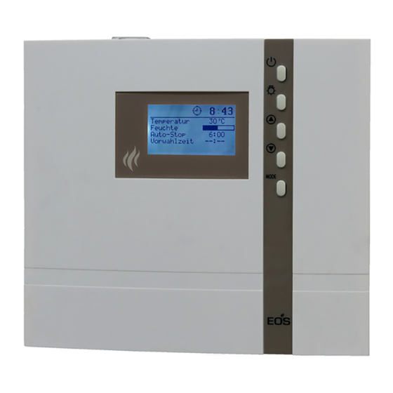
Default display Stand-by is shown if the system is in Stand-by mode. 12:00 Reset to this display takes place from other Temperature 30°C Humidity menu items if no activity is carried out > 15 s. Auto-stop 5 : 59 - - : - - Start time Default display in operation is shown if the system is in operation. -
Page 18: Cabin Lighting
In order to adjust the individual values to the particular desires, briefl y push the MODE -button out of Stand-by. 12:15 Temperature 30°C The modifi able parameter will then be high- Humidity lighted in black and it is possible to select Auto-stop 5 : 59 - - : - -... -
Page 19: Initial Commissioning
Initial commissioning 12:15 12:00 Life - Guard 12:00 12:15 Life - Guard > 3 s MODE > 3 s MODE 00:00 12:00 Time of day Temperature 30°C Humidity : 00 Auto-stop 5 : 59 - - : - - Start time 00:00 12:15 Time of day... -
Page 20: Change Language
Change language Change time 12:00 12:00 Temperatur 30°C Temperature 30°C Feuchte Humidity Auto-Stop 5 : 59 Auto-stop 5 : 59 - - : - - - - : - - Vorwahlzeit Start time & & MODE MODE 12:00 12:15 Time of day Tageszeit 12 : 00 12 : 15... -
Page 21: Activating / Deactivating The Life - Guard
Activate / deactivate the Life - Guard Activate / deactivate the child lock Life - Guard is a settable relatively short If the child lock is activated (the key symbol time, e.g. 20 minutes, after which the sauna is visible in the top section of the display) unit is switched off, except for the cabin light- only the cabin lighting can be switched. -
Page 22: Switching On The Sauna Unit
Switching on the sauna unit Switching on the sauna unit with Life - Guard 12:00 12:00 Temperature 30°C Temperature 30°C Humidity Humidity Auto-stop Auto-stop 5 : 59 5 : 59 - - : - - - - : - - Start time Start time 20 min... -
Page 23: Individual Settings
Individual settings Hereafter we are showing you options that allow you to adjust the controls to your individual needs. The various parameters can be changed in Stand-by or in operation and the changes are saved in the unit. Changes made in operation are effective directly. Setting range: Finnish mode 30 - 115°C Cabin temperature Humidity mode 30 - 70°C... -
Page 24: Humidity Operation
Humidity operation perature sinks towards the cabin fl oor. The following diagram shows you the rela- tive air humidity temperature values for the standard bath forms and comfort zones. The prerequisite for humidity operation is the connection of a suitable evaporator unit up to max. -
Page 25: Humidity Intensity
Humidity intensity If a value is entered here the sauna unit automatically goes into humidity operation when switched on. In Stand-by In operation 12:00 12:15 Temperature 30°C Temperature 30°C Humidity Humidity Auto-stop 5 : 59 Auto-stop 5 : 59 - - : - - Start time - - : - - Start time... -
Page 26: Switching Off The Sauna Unit During Humidity Operation
Switching off the sauna unit during humidity operation In order to dry out the sauna cabin after the humidity operation, a reheating phase is activated after the humidity operation is switched off. The cabin is heated here to 90°C for ca. 30 minutes. This is shown in the upper section of the display with the blink- ing symbol . -
Page 27: Auto-Stop
Auto-Stop Auto-Stop is the time to which the heating time is limited. The sauna unit automatically turns off once this time has expired. Depending on the confi guration of the control, the time is adjustable from 0:01 to 6:00 or 12:00 hours. - Page 28 12:15 12:15 Temperature 30°C Temperature 30°C Humidity Humidity Auto-stop Auto-stop - - : - - - - : - - Start time Start time > 3 s MODE > 3 s MODE 12:15 12:15 Temperature 30°C Temperature 30°C Humidity Humidity Auto-stop 3 : 30 Auto-stop...
-
Page 29: Preselection Time
Preselection time Using the time preselection, you can preselect a switch-on time within 24 hours for your sauna heater. Always make sure that there are no objects on the sauna unit before the heating process begins. Fire risk! Please remember however that the cabin must heat up for approx. 40-50 minutes in order to achieve a pleasant climate in the cabin. -
Page 30: Activate The Preselection Time
12:15 12:15 Temperature 30°C Temperature 30°C Humidity Humidity Auto-stop 5 : 59 Auto-stop 5 : 59 17 : Start time Start time 17 : 12:15 12:15 Temperature 30°C Temperature 30°C Humidity Humidity Auto-stop 5 : 59 Auto-stop 5 : 59 Start time 17 : Start time... -
Page 31: Life - Guard
Life - Guard Here you can set after what time the sauna unit is switched off and by pushing the - but- MODE ton again you can restart the „Life - Guard“ time. This setting can only be selected in Stand-by when the function „Life - Guard“ is activated. In Stand-by 12:00 12:00... -
Page 32: Extend The Time Setting For Sauna Time
Extend heat-up time restriction / replace device fuse By altering a jumper you can extend the heat-up restriction from 6:00 (standard) to 12:00 hours or "indefi nite". Please note that extensions are only allowed in certain commercially operated sauna systems. Only allow a specialist to carry out this work. -
Page 33: Error Messages
Error messages The control unit continuously monitors the sensor for short circuits and interruptions. At the same time, the system checks to ensure that there is enough water in the vaporizer tank. The error messages appear as follows: Display Cause Remedy = interrupted room sensor circuit Arrange for a specialist to... -
Page 34: The Device Switch (Switch-Off)
The device „Switch-o “ switch Switch-o by ECON control units You will nd the rocker switch on the top side of the control unit. You can completely discon- nect the control unit from the mains using this switch. Switch-o Unit turned on (default Position I) Press the switch on the left side of the rocker Unit fully switched o... -
Page 35: Service Address
Outside of Germany please contact your spe- Service Address: cialist dealer in case of warranty claims. Direct warranty processing with our service depart- EOS Saunatechnik GmbH ment is in this case not possible. Schneiderstriesch 1 Equipment commissioning date: 35759 Driedorf, Germany... -
Page 36: General Terms And Conditions Of Service
General Terms and Conditions of Service shipments via parcel post. The manufacturer shall accept no liability for damage incurred as a result of improper I. Scope packaging in an individual shipment. Unless otherwise agreed in writing in a speci c case, the- VI.